Page 228 of 297

7-23INSPECTION AND MAINTENANCE
80J23-03E
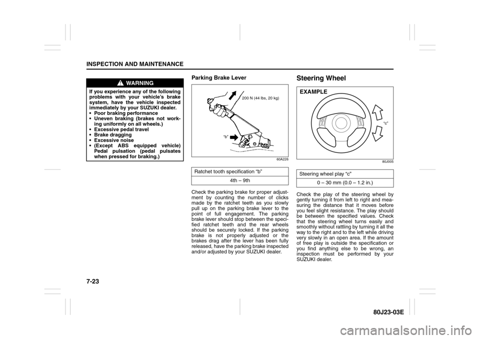
Parking Brake Lever
60A226
Check the parking brake for proper adjust-
ment by counting the number of clicks
made by the ratchet teeth as you slowly
pull up on the parking brake lever to the
point of full engagement. The parking
brake lever should stop between the speci-
fied ratchet teeth and the rear wheels
should be securely locked. If the parking
brake is not properly adjusted or the
brakes drag after the lever has been fully
released, have the parking brake inspected
and/or adjusted by your SUZUKI dealer.
Steering Wheel
80J005
Check the play of the steering wheel by
gently turning it from left to right and mea-
suring the distance that it moves before
you feel slight resistance. The play should
be between the specified values. Check
that the steering wheel turns easily and
smoothly without rattling by turning it all the
way to the right and to the left while driving
very slowly in an open area. If the amount
of free play is outside the specification or
you find anything else to be wrong, an
inspection must be performed by your
SUZUKI dealer.
WARNING
If you experience any of the following
problems with your vehicle’s brake
system, have the vehicle inspected
immediately by your SUZUKI dealer.
Poor braking performance
Uneven braking (brakes not work-
ing uniformly on all wheels.)
Excessive pedal travel
Brake dragging
Excessive noise
(Except ABS equipped vehicle)
Pedal pulsation (pedal pulsates
when pressed for braking.)
Ratchet tooth specification “b”
4th – 9th
200 N (44 lbs, 20 kg)
“b”
Steering wheel play “c”
0 – 30 mm (0.0 – 1.2 in.)
“c”
EXAMPLE
Page 231 of 297

7-26
INSPECTION AND MAINTENANCE
80J23-03E
D. Construction Code
This letter code is used to indicate
the type of ply construction in the
tire. The letter “R” means radial
ply tire construction, the letter “D”
means diagonal or bias ply con-
struction, and the letter “B” means
belted-bias ply construction.
E. Rim Diameter
This two-digit number is the wheel
or rim diameter in inches.Tire Inflation Pressure
Tire inflation pressure should be
checked when the tire is cold. “Cold
tire inflation pressure” is the pressure
in a tire that has been driven less than
1 mile (1.6 km) or has been standing
for three hours or more.
80JS025
The front and rear tire pressure speci-
fications for your vehicle are shown
below and are listed on the Tire and
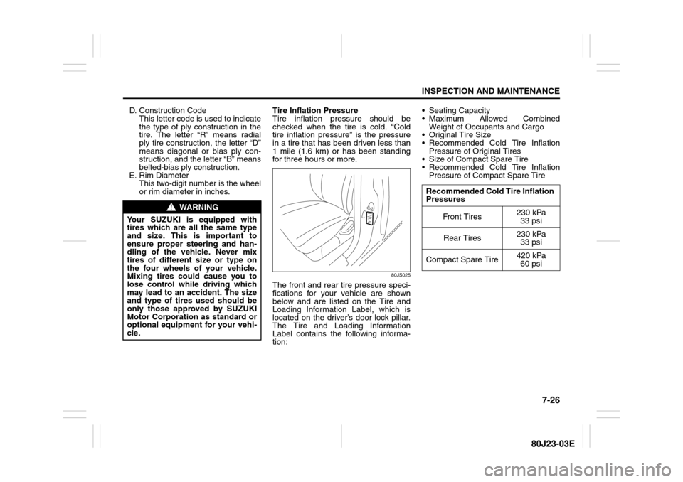
Loading Information Label, which is
located on the driver’s door lock pillar.
The Tire and Loading Information
Label contains the following informa-
tion: Seating Capacity
Maximum Allowed Combined
Weight of Occupants and Cargo
Original Tire Size
Recommended Cold Tire Inflation
Pressure of Original Tires
Size of Compact Spare Tire
Recommended Cold Tire Inflation
Pressure of Compact Spare Tire
WARNING
Your SUZUKI is equipped with
tires which are all the same type
and size. This is important to
ensure proper steering and han-
dling of the vehicle. Never mix
tires of different size or type on
the four wheels of your vehicle.
Mixing tires could cause you to
lose control while driving which
may lead to an accident. The size
and type of tires used should be
only those approved by SUZUKI
Motor Corporation as standard or
optional equipment for your vehi-
cle.
Recommended Cold Tire Inflation
Pressures
Front Tires230 kPa
33 psi
Rear Tires230 kPa
33 psi
Compact Spare Tire420 kPa
60 psi
Page 242 of 297

7-37INSPECTION AND MAINTENANCE
80J23-03E
The main fuse, primary fuses and some of
the individual fuses are located in the
engine compartment. If the main fuse
blows, no electrical component will func-
tion. If a primary fuse blows, no electrical
component in the corresponding load
group will function. When replacing the
main fuse, a primary fuse or an individual
fuse, use a genuine SUZUKI replacement.
To remove a fuse, use the fuse puller pro-
vided in the fuse box. The amperage of
each fuse is shown in the back of the fuse
box cover.
60A243
NOTE:
Make sure that the fuse box always carries
spare fuses. MAIN FUSE / PRIMARY FUSE
(1) 80A All electric load
(2) 50APower window, Ignition,
Wiper, Starter
(3) 50ATail light, Rear defogger,
Door lock, Hazard/Horn,
Dome
(4) – Blank
(5) – Blank
(6) 15A Head light (Right) fuse
(7) 15A Head light (Left) fuse
(8) 20A Front fog light fuse
(9) – Blank
(10) 40A ABS motor fuse
(11) 30A Radiator fan fuse
(12) 30A ABS solenoid fuse
(13) 30A Starting motor fuse
(14) 50A Ignition switch fuse
(15) 30A Blower fan fuse
(16) 20A Air compressor fuse
(17) 15A Throttle motor fuse
(18) 15A Automatic transaxle fuse
(19) 15A Fuel injection fuse
(20) – Automatic transaxle relay
(21) – Air compressor relay
(22) – Fuel pump relay
(23) – Condenser fan relay
(24) – Front fog light relay
(25) – Throttle motor relay
(26) – FI MAIN relay
(27) – Starting motor relay
(28) – Radiator fan relay
(29) – Radiator fan relay 2
(30) – Radiator fan relay 3
WARNING
If the main fuse or a primary fuse
blows, be sure to have your vehicle
inspected by an authorized SUZUKI
dealer. Always use a genuine SUZUKI
replacement. Never use a substitute
such as a wire even for a temporary
fix, or extensive electrical damage
and a fire can result.
BLOWNOK
Page 243 of 297
7-38
INSPECTION AND MAINTENANCE
80J23-03E
Fuses under the Dash Board
79J093
SX4
80J053
SX4 SEDAN
80JC003
(1) (2) (3) (4) (5) (6)
(8) (9) (10) (11) (12) (13) (14) (15) (16)
(18) (17) (19) (20) (21) (22) (23)(7)
MAIN FUSE / PRIMARY FUSE
(1) 15A Rear wiper
(2) 15A Ignition coil
(3) 10A Back-up light
(4) 10A Meter
(5) 15A Accessory
(6) 15A Accessory 2
(7) 30A Power window
(8) 30A Wiper
(9) 10A IG1 SIG
(10) 15A Air bag
(11) 10A Anti-lock brake system
(12) 15A 4WD
(13) 10A Stop light
(14) 20A Door lock
(15) 10A Rear fog light
(16) 10A ST SIG
(17) 15A Seat heater
(18) 10A IG 2 SIG
(19) 10A Tail light
(20) 15A Dome
(21) 30A Rear defogger
(22) 15A Horn / Hazard
(23) – Blank
MAIN FUSE / PRIMARY FUSE
(1) 15A Rear wiper
(2) 15A Ignition coil
(3) 10A Back-up light
(4) 10A Meter
(5) 15A Accessory
(6) 15A Accessory 2
(7) 30A Power window
(1) (2) (3) (4) (5) (6)
(8) (9) (10) (11) (12) (13)
(21)
(24)
(14) (15) (16)
(18) (17) (19) (20) (22) (23)(7)
Page 244 of 297

7-39INSPECTION AND MAINTENANCE
80J23-03E
The fuses are also located under the
driver’s side of the dashboard. Remove the
fuse box cover by pulling it off. The amper-
age of each fuse is shown on the top of the
fuse box cover.
65D046
Headlight AimingSince special procedures are required, we
recommend you take your vehicle to your
SUZUKI dealer for headlight alignment. (8) 30A Wiper
(9) 10A IG1 SIG
(10) 15A Air bag
(11) 10A Anti-lock brake system
(12) – Blank
(13) 10A Stop light
(14) 20A Door lock
(15) 10A Rear fog light
(16) 10A ST SIG
(17) 15A Seat heater
(18) 10A IG 2 SIG
(19) 10A Tail light
(20) 15A Dome
(21) 30A Rear defogger
(22) 15A Horn / Hazard
(23) – Blank
(24) 30A Rear defogger
WARNING
Always be sure to replace a blown
fuse with a fuse of the correct amper-
age. Never use a substitute such as
aluminum foil or wire to replace a
blown fuse. If you replace a fuse and
the new one blows in a short period
of time, you may have a major electri-
cal problem. Have your vehicle
inspected immediately by your
SUZUKI dealer.
BLOWN OK
Page 246 of 297
7-41INSPECTION AND MAINTENANCE
80J23-03E
Headlights
80J2084
Open the engine food. Disconnect the cou-
pler (1). Then remove the socket cover (2)
and replace the bulb. Install a new bulb in
the reverse order of removal.
Other General LightsBulb holder
54G123
(1) Removal
(2) Installation
To remove a bulb holder from a light hous-
ing, turn the holder counterclockwise and
pull it out. To install the holder, push the
holder in and turn it clockwise.Bulb
54G124
(3) Removal
(4) Installation
There are two types of bulb, “Full glass
type” (1) and “Glass/metal type” (2).
To remove and install a full glass type bulb
(1), simply pull out or push in the bulb.
To remove a glass metal type bulb (2) from
a bulb holder, push in the bulb and turn it
counterclockwise. To install a new bulb,
push it in and turn it clockwise.
You can access the individual bulb or bulb
holders as follows.
(1)(2)
(1)
(1) (2)(2)
EXAMPLE
(1)
(2) (3)
(4)EXAMPLE
Page 248 of 297
7-43INSPECTION AND MAINTENANCE
80J23-03E
SX4
80JM116
4) Open the fender cover. Disconnect the
coupler by pushing the lock release.
Pinch both side of the clips (4) and (5),
and push them in.
80JM117
5) Remove the front fog light. Turn the
bulb holder counterclockwise and
remove it.
SX4 SEDAN
80JM071
4) Open the fender cover. Disconnect the
coupler with pushing the lock release.
Turn the bulb holder counterclockwise
and remove it.Rear combination light
(tail, stop, turn signal, etc.)
SX4
80JM131
SX4 SEDAN
80JM072
(4)
(5)
EXAMPLE
(2)
(1)
Page 252 of 297
7-47INSPECTION AND MAINTENANCE
80J23-03E
For windshield wipers and some rear
wipers:
70G119
1) Hold the wiper arm away from the win-
dow.
NOTE:
When raising both of the front wiper arms,
pull the driver’s side wiper arm up first.
When returning the wiper arms, lower the
passenger’s side wiper arm first. Other-
wise, the wiper arms may interfere with
each other.
52D102
2) Squeeze lock lever (1) towards wiper
arm (2) and remove the wiper frame
from the arm as shown.
60A260
3) Pull the locked end of the wiper blade
firmly to unlock the blade and slide the
blade out as shown.