2010 SKODA ROOMSTER lock
[x] Cancel search: lockPage 51 of 231
Lights and Visibility
50
The turn signal
and main beam lever
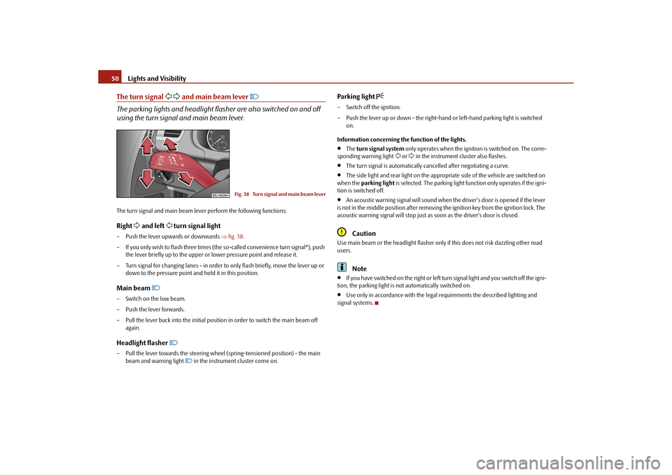
The parking lights and headlight flas her are also switched on and off
using the turn signal and main beam lever.The turn signal and main beam le ver perform the following functions:Right
and left
turn signal light
– Push the lever upwards or downwards fig. 38 .
– If you only wish to flash three times (the so-called convenience turn signal*), push
the lever briefly up to the upper or lower pressure point and release it.
– Turn signal for changing lanes - in order to only flash briefly, move the lever up or
down to the pressure point and hold it in this position.Main beam
– Switch on the low beam.
– Push the lever forwards.
– Pull the lever back into the initial positi on in order to switch the main beam off
again.Headlight flasher
– Pull the lever towards the steering wheel (spring-tensioned position) - the main beam and warning light
in the instrument cluster come on.
Parking light
– Switch off the ignition.
– Push the lever up or down - the right-hand or left-hand parking light is switched
on.
Information concerning the function of the lights.
The turn signal system only operates when the ignition is switched on. The corre-
sponding warning light
or in the instrument cluster also flashes.
The turn signal is automatically cancelled after negotiating a curve.
The side light and rear light on the appropriate side of the vehicle are switched on
when the parking light is selected. The parking light function only operates if the igni-
tion is switched off.
An acoustic warning signal will sound when the driver's door is opened if the lever
is not in the middle position after removing the ignition key from the ignition lock. The
acoustic warning signal will stop just as soon as the driver's door is closed.Caution
Use main beam or the headlight flasher only if this does not risk dazzling other road
users.
Note
If you have switched on the right or left turn signal light and you switch off the igni-
tion, the parking light is no t automatically switched on.
Use only in accordance with the legal requirements the described lighting and
signal systems.
Fig. 38 Turn signal and main beam lever
s16g.4.book Page 50 Wednesda y, February 10, 2010 3:53 PM
Page 52 of 231

Lights and Visibility51
Using the system
Safety
Driving Tips
General Maintenance
Breakdown assistance
Praktik
Technical Data
Interior lightingFront interior lighting and storage compartment on front passenger sideDoor contact switching mechanism (front and rear* doors)– Press the switch
to the right into position fig. 39 .
– On the version without reading lights press the switch into the middle position
.
Switching the interior light on– Press the switch to the left into position
.
Switching the interior light off– Press the switch into the middle position O.
– On the version without reading lights press the switch to the right, the symbol O appears.Reading lights
– Press on one of the switches fig. 39 in order to switch the right or left reading
light on or off.
Lighting of storage compartme nt on the front passenger side– When opening the flap of the storage compartment on the front passenger side the
lighting in the storage compartment comes on.
– The light switches on automatically when the parking light is switched on and goes
out when the flap is closed.
On vehicles with central locking, the interior light is switched on for about 30 seconds
when the vehicle is unlocked, when a door is opened or after withdrawing the ignition
key (if the relevant switch is in the door contact position). The inner light goes out out
immediately after the ignition is switched on.
A time delay switch* causes the inner lighting on vehicles without a central locking
system stays on for a few seconds after the doors have been closed. The inner light
goes out out immediately after the ignition is switched on.
The interior lighting is switched off after about 10 minutes when a door has been left
open in order to avoid discharg ing the battery of the vehicle.Rear interior lighting*The rear interior lighting fig. 40 is actuated by moving the switch to the symbol
,
O or to the middle position
.
The same principles apply for th e interior lighting at the rear as for the for the interior
lighting at the front page 51.
Fig. 39 Detail of the headliner: front
interior lighting
AA
AA
AAAA
AA
AB
Fig. 40 Roof liner light
s16g.4.book Page 51 Wednesda y, February 10, 2010 3:53 PM
Page 55 of 231

Lights and Visibility
54
Do not use the windscreen washer sy stem at low temperatures, without
heating the windscreen beforehand. Otherwise the window cleaner could
freeze on the windscreen and re strict the view to the front.
In the event of a freezing up of the wi ndscreen, first of all eliminate the ice
page 153 and then operate the windscr een wiper otherwise the windscreen
wiper blades could be damaged.Caution
In frosty weather, please firs t of all check whether the windscreen wiper blades are not
frozen to the windscreen before switching them on. Switching on windscreen wipers
when the blades are frozen to the windscreen may result in damage both to the blades
and the motor of the windscreen wipers!
Note
The content of the windscreen wiper reserv oir is 3.5 litres. On vehicles which are
equipped with a headlight cleaning system*, the content of the reservoir is 5.4 litres.Headlight cleaning system*The headlights are being cleaned after the windscreen washer system has been oper-
ated for the fifth time, the low beam or main beam are switched on as well as the wind-
screen wiper lever is held in the position page 53, fig. 43 for about 1 second.
You should remove stubborn dirt (such as in sect residues) from the headlight lenses at
regular intervals, for example when refuelling . Please refer to the following guidelines
page 154, “The headlight lenses”.
You should remove any snow from the fixtur es of the washer nozzles and clear ice in
winter with a de-icing spray in order to ensure proper operation of the cleaning
system.
Replacing wiper blades for the windscreen wipersTaking off the wiper blade– Fold windscreen wiper arm away from the windscreen.
– Press the locking button, in order to un lock the wiper blade and pull off in the
direction of arrow.Attaching a wiper blade– Push the wiper blade until it locks up to the stop.
– Check whether the wiper blade is correctly attached.
– Fold the windscreen wiper ar m back onto the windscreen.
Wiper blades in proper condition are essentia l to obtain good visibility. Wiper blades
should not be allowed to become dirtied by dust, insect remains and preserving wax.
Juddering or smearing of the wiper blades co uld then be due to wax residues left on
the windscreen by vehicle washing in automa tic vehicle wash systems. It is therefore
important to degrease the lips of the wiper blades after every pass through an auto-
matic vehicle wash system .
WARNING
If the windscreen wipers are handled ca relessly, there is a risk of damage to
the windscreen.
WARNING (continued)
A5
Fig. 44 Wiper blade for the windscreen
wiper
s16g.4.book Page 54 Wednesda y, February 10, 2010 3:53 PM
Page 56 of 231

Lights and Visibility55
Using the system
Safety
Driving Tips
General Maintenance
Breakdown assistance
Praktik
Technical Data
You should clean the wiper blades regularly with a windscreen cleaner in
order to avoid any smears. Clean a wiper blad e with a sponge or cloth if it is very
dirty, for example from insect residues.
Replace the wiper blades once or twice a year for safety reasons. The wiper
blades are available from specialist garages.
Replacing the wiper blade on the rear window wiperTaking off the wiper blade– Fold windscreen wiper arm out from the windscreen and position the wiper blade at right angles to the wiper arm fig. 45 .
– Hold the window wiper arm at the top end with one hand.
– With the other hand unlock the locking button in the direction of arrow and remove the wiper blade.Attaching a wiper blade– Position the wiper blade onto the wiper arm and lock the locking button .
– Check whether the wiper bl ade is correctly attached.
The same remarks apply here as for page 54.
Rear mirrorYou can adjust the exterior mirrors electrically*.Adjust the rear mirror before commencing to drive so that there is a clear view to the
rear.Dimming the interior mirror– Pull the lever on the bottom edge of the mirror toward rear (the lever on the inte-
rior mirror must point forwards in it home position).Heating of the external mirror*– Turn the rotary knob to position
fig. 46 .
Adjusting the left-hand exterior mirror*– Turn the rotary knob to position
. The movement of the mirror surface is identical
to the movement of the rotary knob.
Adjusting the right-hand exterior mirror*– Turn the rotary knob to position
. The movement of the mirror surface is identical
to the movement of the rotary knob.
The vehicle can also be equipp ed with a second rear mirror*, which is attached above
the inner main rear mirror. The second rear mirror* enables an extensive look into the
area of the rear seats, e.g. to check on the seated passengers. You can adjust it in the
horizontal as well as vertical direction re gardless of the inner main rear mirror.
WARNING (continued)
Fig. 45 Wiper blade for rear windowAA
AA
Fig. 46 Inner part of door: Rotary knob
s16g.4.book Page 55 Wednesday, February 10, 2010 3:53 PM
Page 58 of 231

Seats and Storage57
Using the system
Safety
Driving Tips
General Maintenance
Breakdown assistance
Praktik
Technical Data
Seats and StorageFront seatsBasic informationThe front seats have a wide range of differ ent settings and can thus be matched to the
physical characteristics of the driver and front passenger. Correct adjustment of the
seats is particularly important for:
safely and quickly reaching the controls;
a relaxed, fatigue-free body position;
achieving the maximum protection offered by the seat belts and the airbag
system.
The chapters which follow describe the procedure which you should adopt for
adjusting the seats.
WARNING
Never transport more occupants than the maximum seating in the vehicle.
Each occupant must correctly fasten the seat belt belonging to the seat.
Children must be fastened page 126, “Transporting children safely” with a
suitable restraint system.
The front seats and the head restraints must always be adjusted to match
the body size of the seat occupant as well as the seat belts must always be
correctly fastened in order to provide an optimal protection for you and your
occupants.
Always keep your feet in the footwell when the vehicle is being driven -
never place your feet on the instrument panel, out of the window or on the
surfaces of the seats. This is particular ly important for the front seat passenger.
You will be exposed to increased risk of injury if it becomes necessary to apply
the brake or in the event of an accident. If an airbag is deployed, you may suffer
fatal injuries when adopting an incorrect seated position!
It is important for the driver and front passenger to maintain a distance of at
least 25 cm from the steering wheel or dash panel. Not maintaining this
minimum distance will mean that the airbag system will not be able to properly protect you - hazard! The front seats and the head restraints must always also
be correctly adjusted to match the body size of the occupant.
Ensure that there are no objects in
the footwell as any objects may get
behind the pedals during a driving or braking manoeuvre. You would then no
longer be able to operate the clutch, to brake or accelerate.
Do not transport any objects on the front passenger seat except those
provided for this purpose (e.g. child safety seat) - risk of accident!
Adjusting the front seatsAdjusting a seat in a forward/back direction–Pull the lever fig. 47 up and push the seat into the desired position.
– Release the lever and push the seat further until the lock is heard to engage.Adjusting height of seat*– Lift the seat if required by pulling or pumping lever upwards.
– Lower the seat if required by pushing or pumping lever downwards.
WARNING (continued)
Fig. 47 Controls at seat
A1A1
A2A2
s16g.4.book Page 57 Wednesda y, February 10, 2010 3:53 PM
Page 59 of 231
Seats and Storage
58
Adjust the angle of the seat backrest
– Relieve any pressure on the seat backrest (do not lean on it) and turn the hand-
wheel to adjust the angle of the backrest.
The driver's seat should be adjusted in such a way that the pedals can be fully pressed
to the floor with slightly bent legs.
The seat backrest on the driver's seat should be adjusted in such a way that the upper
point of the steering wheel can be easi ly reached with slightly bent arms.
WARNING
Only adjust the driver seat when the vehicle is stationary - risk of injury!
Take care when adjusting the seat! Adjusting the seat without care can lead
to bruises or injuries.
The seat backrests must not be angled too far back when driving otherwise
this will affect proper operation of the se at belts and of the airbag system - risk
of injury!
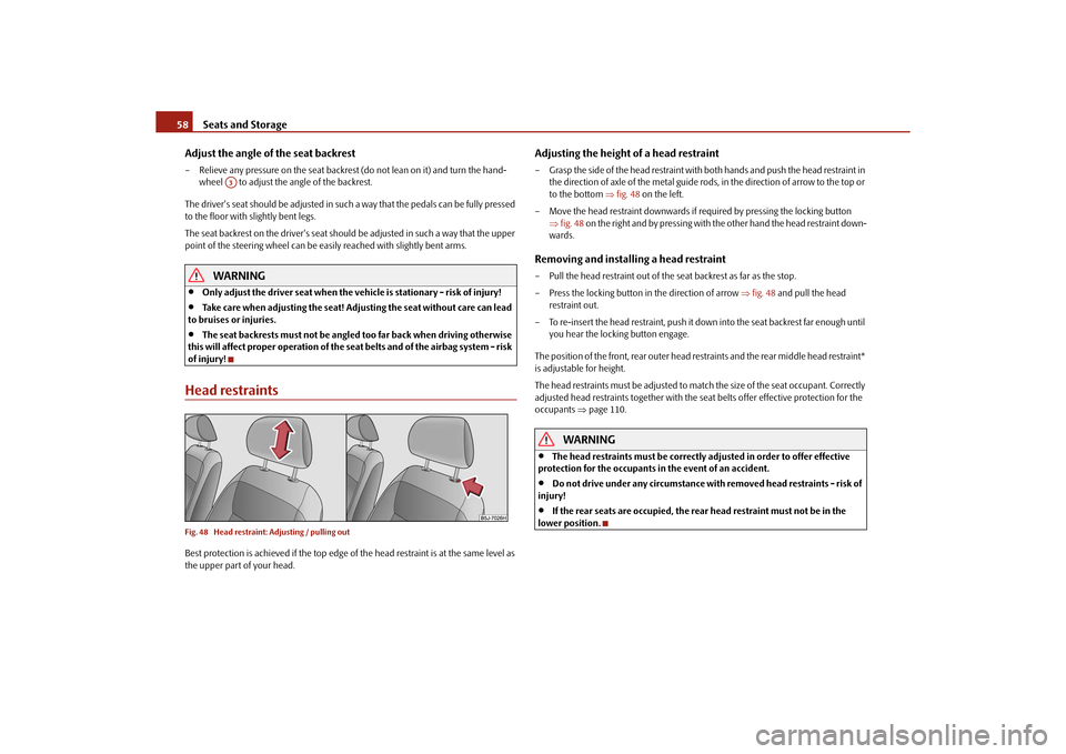
Head restraintsFig. 48 Head restraint: Adjusting / pulling outBest protection is achieved if the top edge of the head restraint is at the same level as
the upper part of your head.
Adjusting the height of a head restraint– Grasp the side of the head restraint with both hands and push the head restraint in the direction of axle of the metal guide rods, in the direction of arrow to the top or
to the bottom fig. 48 on the left.
– Move the head restraint downwards if required by pressing the locking button fig. 48 on the right and by pressing with the other hand the head restraint down-
wards.Removing and installing a head restraint– Pull the head restraint out of the seat backrest as far as the stop.
– Press the locking button in the direction of arrow fig. 48 and pull the head
restraint out.
– To re-insert the head restraint, push it do wn into the seat backrest far enough until
you hear the locking button engage.
The position of the front, rear outer head restraints and the rear middle head restraint*
is adjustable for height.
The head restraints must be adjusted to ma tch the size of the seat occupant. Correctly
adjusted head restraints together with the seat belts offer effective protection for the
occupants page 110.
WARNING
The head restraints must be correctly adjusted in order to offer effective
protection for the occupants in the event of an accident.
Do not drive under any circumstance with removed head restraints - risk of
injury!
If the rear seats are occupied, the rear head restraint must not be in the
lower position.
A3
s16g.4.book Page 58 Wednesda y, February 10, 2010 3:53 PM
Page 61 of 231

Seats and Storage
60
Adjusting the seat backrestAdjust the angle of the seat backrest– Pull the lever fig. 51 and adjust the desired angle of the seat backrest.Folding seats forwardsFig. 52 Fold seat fully forwards / Secure folded forward seatsFold seats fully forwards and secure– Open the guide loop for the seat belt on th e side of the outer seats and put the belt
tongue into the opening on the respective side trim panel - safety holder.
– Move the seat as far as possible to the rear page 59.
– Pull the lever fig. 51 and fold the seat backrest fully fowards.
– Pull the lever fig. 52 up and then fold the seat fully forwards. – Secure the folded forward seat with the aid of the fixing belt to a guide rod of the
head restraint for the front seat fig. 52 on the right.
WARNING
Immediately secure the folded forward seat with the aid of the fixing belt to
a guide rod of the head restraint for the front seat - there is a risk of injury as
soon as the vehicle starts off.
If the seat is not in the rear end po sition, damage can occur to the locking
bolts if the seat is unlocked.Note
Please refer to the following guidelines page 111, “Correct seated position for the
occupants on the rear seats”.Removing seatsFig. 53 Unlocking the folded forward seat / carrying handle on the seat cushionUnlocking and removing seats– Unlock the folded forward seat by pressing the seat locks in the direction of arrow fig. 53 .
– Remove the seat with the carrying handle on the seat cushion fig. 53 on the
right.
Fig. 51 Adjusting the seat backrest
s16g.4.book Page 60 Wednesda y, February 10, 2010 3:53 PM
Page 62 of 231

Seats and Storage61
Using the system
Safety
Driving Tips
General Maintenance
Breakdown assistance
Praktik
Technical Data
Note
The outer seats are not replac eable alternatively. In the rear area the left seat is
marked with the letter L and the right seat with the letter R.
Please refer to the following guidelines page 111.
Adjusting seats in crosswise directionMoving seats in crosswise direction– Remove the middle seat page 60.
– Fold the outer seat forwards page 60 and lock it page 60, fig. 53 .
– Move the folded forward and unlocked seat on the guide towards the middle of the vehicle up to the stop.
– Lock the seat at the end of the guide fig. 54 .
Move seats into the initial positionLocking seats and folding back into position– If the seat is removed, first of all position it on the guide and lock the seat fig. 54 .
Check for yourself that the seat is correctly locked by pulling it up.
– Fold the seat into the horizontal position until it is heard to lock. Check for yourself that the seat can no longer be lifted by pulling it up.
– Push the lever fig. 55 and fold the backrest back in to position. Check for yourself
that the seat backrest is engaged.
– Take the belt tongue out of the safety holder.
– Close the guide loop of the seat belt on the side of the outer seats until it is heard to lock.
WARNING
The belt locks and the belts must be in their original position after folding
back the seat cushions and the seat backrests - they must be ready to use.
The seat backrests must be securely interlocked in position so that no
objects in the luggage compartment can slide into the passenger compartment
if there is sudden braking - risk of injury!
When folding the seat backrest always make sure that it has safely locked
into position, this is confirmed by the position and a visible marking on the
cover of the lever.
Fig. 54 Locking the seat
Fig. 55 Folding the seat backrest back
into position
s16g.4.book Page 61 Wednesda y, February 10, 2010 3:53 PM