Page 65 of 275
 Owners Manual Lights and Visibility
64
You should clean the wiper blades regularly with a windscreen cleaner in
order to avoid any smears. Clean a wiper blad e with a sponge or cloth if it is very
dirty, for")
Lights and Visibility
64
You should clean the wiper blades regularly with a windscreen cleaner in
order to avoid any smears. Clean a wiper blad e with a sponge or cloth if it is very
dirty, for example from insect residues.
Replace the wiper blades once or twice a year for safety reasons. These can
be bought from an authorised Škoda Service Partner.
Replacing the wiper blade on the rear window wiperTaking off the wiper blade – Fold windscreen wiper arm out from the windscreen and position the wiper blade at right angles to the wiper arm fig. 52 .
– Hold the window wiper arm at the top end with one hand.
– With the other hand unlock the locking button in the direction of arrow and remove the wiper blade.Attaching a wiper blade– Position the wiper blade onto the wiper arm and lock the locking button .
– Check whether the wiper blade is correctly attached.
The same remarks apply here as for page 63.
Rear-view mirrorManual dimming interior rear-view mirrorBasic setting– Pull the lever on the bottom edge of the mirror forward.Dimming mirror– Pull the lever on the bottom edge of the mirror back.Automatic dimming interior mirror*Switching on the automatic dimming– Press the button - the warning light lights up fig. 53 .Switching off the automatic dimming– Press again the button - the warning light goes out .
If the automatic dimming is switched on, the mirror dims automatically depending on
the light striking the mirror from the rear. The mirror has no lever on the bottom edge
of the mirror. After the reverse gear is engaged, the mirror always moves back into the
normal position.
WARNING (continued)
Fig. 52 Wiper blade for rear windowAA
AA
Fig. 53 Automatic dimming interior
mirror
AB
AA
AB
AA
s43s.1.book Page 64 Thursday, May 13, 2010 1:21 PM
Page 66 of 275
 Owners Manual Lights and Visibility65
Using the system
Safety
Driving Tips
General Maintenance
Breakdown assistance
Technical Data
Note
Automatic mirror dimming operates only properly if the sun screen* for the")
Lights and Visibility65
Using the system
Safety
Driving Tips
General Maintenance
Breakdown assistance
Technical Data
Note
Automatic mirror dimming operates only properly if the sun screen* for the rear
window in the housing on the luggage compartment cover is not in use or the light
striking the interior rear-view mirr or is not affected by other objects.
Do not affix any stickers in front of the light sensor, so that you do not impair the
automatic dimming function or put it out of operation.
If you switch off the automatic dimming inte rior rear-view mirror, also the exterior
mirror dimming is switched off.
Exterior mirror
You can adjust the exterior mirrors electrically*.The exterior mirror he ater only operates when the en gine is running and up to an
outside temperature of +20 °C. Heating of the external mirror – Turn the rotary knob to position
fig. 54 .
Adjusting left and right exterior mirrors simultaneously– Turn the rotary knob to position
. The movement of the mirror surface is identical
to the movement of the rotary knob.
Adjusting the right-hand exterior mirror– Turn the rotary knob to position
. The movement of the mirror surface is identical
to the movement of the rotary knob.
Switching off operating control– Turn the rotary knob to position
.
Folding in both exterior mirrors*– Turn the rotary knob to position
.
Folding exterior mirrors* using the key with radio remote control– If all the windows are closed, press the unlock button on the radio remote
control page 43, fig. 31 for approx. 2 seconds.
Tilting surface of front pa ssenger exterior mirror*
When the rotary knob is in position
fig. 54 and the reverse gear is engaged, the
surface of the mirror tilts down slightly. This provides an aid in seeing the kerb of the
pavement when parking the car.
The mirror returns into its initial position, after the rotary knob is moved out of the
position
and put into another position or if the speed is more than 15 km/h.
Memory for exterior mirrors*
On vehicles fitted with a memory for the driver seat, the relevant setting of the exterior
mirror is also stored automatically when the se at position is stored page 68.WARNING
Convex (curved outward) or spherical (differently curved) exterior mirrors
increase the vision field. They do, however, make objects appear smaller in the
mirror. These mirrors are only of limited use, therefore, for estimating distances
to the following vehicles.
Use whenever possible the interior rear mirror, for estimating the distances
to the following vehicles.
Fig. 54 Inner part of door: Rotary knob
A3
s43s.1.book Page 65 Thursday, May 13, 2010 1:21 PM
Page 67 of 275
 Owners Manual Lights and Visibility
66Note
If the exterior mirrors are folded in using the remote control* of the vehicle key,
these are folded back into the driving positi on after opening the door or switchi")
Lights and Visibility
66Note
If the exterior mirrors are folded in using the remote control* of the vehicle key,
these are folded back into the driving positi on after opening the door or switching on
the ignition.
If the exterior mirrors are folded in using the rotary knob page 65, fig. 54 , they
can only be folded back into the dr iving position using the rotary knob.
If the exterior mirrors were folded in us ing the remote control* of the vehicle key
and if the rotary knob was in the fold-in po sition before switching on the ignition, the
mirrors remain in the fold-in position the next time the ignition is switched on. Folding
back into the driving position is performed by actuating the rotary knob in a different
position from the fold-in position.
Do not touch the surfaces of the exterior mirrors if the exterior mirror heater is
switched on.
You can set the exterior mirrors by hand, if the power setting function fails at any
time by pressing on the edge of the mirror surface.
Contact your specialist garage if a fault ex ists with the power setting of the exterior
mirrors.
Automatic dimming exterior mirror on the driver's side*The exterior mirror on the driver's side is dimmed together with the interior mirror. If
the automatic dimming is switched on, the mirror dims automatically depending on
the light striking the mirror from the rear.
After the reverse gear is engaged, the mirror always moves back into the normal (not
dimmed) position.
Note
Automatic mirror dimming operates only properly if the sun screen* for the rear
window is not in use or the light striking the rear of the interior rear-view mirror is not
affected by other objects.
Do not affix any stickers in front of the light sensor, so that you do not impair the
automatic dimming function or put it out of operation.
If you switch off the automatic dimming interior rear-view mirror, also the exterior
mirror dimming is switched off.
s43s.1.book Page 66 Thursday, May 13, 2010 1:21 PM
Page 68 of 275
 Owners Manual Seats and Stowage67
Using the system
Safety
Driving Tips
General Maintenance
Breakdown assistance
Technical Data
Seats and StowageFront seatsBasic informationThe front seats have a wide range of diffe")
Seats and Stowage67
Using the system
Safety
Driving Tips
General Maintenance
Breakdown assistance
Technical Data
Seats and StowageFront seatsBasic informationThe front seats have a wide range of differ ent settings and can thus be matched to the
physical characteristics of the driver and front passenger. Correct adjustment of the
seats is particularly important for:
safely and quickly reaching the controls,
a relaxed, fatigue-free body position,
achieving the maximum protection offered by the seat belts and the airbag
system.
WARNING
Never transport more occupants than the maximum seating in the vehicle.
Each occupant must correctly fasten the seat belt belonging to the seat.
Children must be fastened page 159, “Transporting children safely” with a
suitable restraint system.
The front seats and the head restraints must always be adjusted to match
the body size of the seat occupant as well as the seat belts must always be
correctly fastened in order to provide an optimal protection for you and your
occupants.
Always keep your feet in the footwell when the vehicle is being driven -
never place your feet on the instrument panel, out of the window or on the
surfaces of the seats. This is particular ly important for the front seat passenger.
You will be exposed to increased risk of injury if it becomes necessary to apply
the brake or in the event of an accident. If an airbag is deployed, you may suffer
fatal injuries when adopting an incorrect seated position!
It is important for the driver and front passenger to maintain a distance of at
least 25 cm from the steering wheel or dash panel. Not maintaining this
minimum distance will mean that the airbag system will not be able to properly
protect you - hazard! The front seats and the head restraints must always also
be correctly adjusted to match the body size of the occupant.
Ensure that there are no objects in the footwell as any objects may get
behind the pedals during a driving or braking manoeuvre. You would then no
longer be able to operate the clutch, to brake or accelerate.
Adjusting the front seatsAdjusting a seat in a forward/back direction–Pull the lever fig. 55 up and push the seat into the desired position.
– Release the lever and push the seat further until the lock is heard to engage.Adjusting height of seat*– Lift the seat if required by pulling or pumping lever upwards.
– Lower the seat if required by pushing or pumping lever downwards.Adjust the angle of the seat backrest– Relieve any pressure on the seat backrest (do not lean on it) and turn the hand- wheel fig. 55 to adjust the desired angle of the backrest.
WARNING (continued)
Fig. 55 Controls at seat
A1A1
A2A2
A3
s43s.1.book Page 67 Thursday, May 13, 2010 1:21 PM
Page 69 of 275
 Owners Manual Seats and Stowage
68
Adjusting lumbar support*
– Turn the wheel until you have set the most comfortable curvature of the seat
upholstery in the area of your spine.
The drivers seat should be ad")
Seats and Stowage
68
Adjusting lumbar support*
– Turn the wheel until you have set the most comfortable curvature of the seat
upholstery in the area of your spine.
The driver's seat should be adjusted in such a way that the pedals can be fully pressed
to the floor with slightly bent legs.
The seat backrest on the driver's seat should be adjusted in such a way that the upper
point of the steering wheel can be easi ly reached with slightly bent arms.
WARNING
Only adjust the driver seat when the vehicle is stationary - risk of injury!
Take care when adjusting the seat! Adjusting the seat without care can lead
to bruises or injuries.
The seat backrests must not be angled too far back when driving otherwise
this will affect proper operation of the se at belts and of the airbag system - risk
of injury!
Adjusting front seats electrically*Adjusting seatsFig. 56 Side view: Controls for adju sting the seat / seat setting switchAdopt the correct seated position before setting page 67.
Adjusting a seat in a forward/back direction– Press the switch fig. 56 forwards or backwards .Set the height of the seat cushion– Press the switch upwards or downwards.Adjust the angle of the seat cushion– Press the switch at the front or at the back .Adjusting the seat backrest– Press the switch in the direction of the desired setting.Adjusting lumbar support– Press the switch front fig. 56 in order to enlarge the curvature of the lumbar
support.
– Press the switch rear in order to reduce the curvature of the lumbar support.
– Press the switch top in order to adjust the curvature of the lumbar support higher.
– Press the switch bottom in order to adjust the curvature of the lumbar support lower.
Switch is operated in order to move the seat up/down and forward/back, while
switch is operated in order to move the seat backrest forward or back.
WARNING
Only adjust the driver seat when the ve hicle is stationary - risk of injury!
Caution when adjusting the seat! You ma y suffer injuries or bruises as a
result of adjusting the seat without paying proper attention.
In view of the fact that the seats can also be adjusted when the ignition is
switched off (even when ignition key withdrawn), you should never leave chil-
dren unattended in the vehicle.
A4
AA
A1
AAAA
A2
A3
ABACACACAC
AAAB
s43s.1.book Page 68 Thursday, May 13, 2010 1:21 PM
Page 70 of 275
 Owners Manual Seats and Stowage69
Using the system
Safety
Driving Tips
General Maintenance
Breakdown assistance
Technical Data
The seat backrests must not be angled too far back when driving otherwise
this wil")
Seats and Stowage69
Using the system
Safety
Driving Tips
General Maintenance
Breakdown assistance
Technical Data
The seat backrests must not be angled too far back when driving otherwise
this will affect proper operation of the se at belts and of the airbag system - risk
of injury!Note
If the movement of the seat is inadverten tly interrupted during an adjustment, once
again press the switch in the appropriate di rection and continue with the adjustment
of the seat to the end.Storing settingStoring seat and exterior mirror settings for driving forward– Switch on the ignition.
– Adjust the seat page 68.
– Adjust both exterior mirrors page 65.
– Press button SET fig. 57 .
– Press one of the memory buttons with in 10 seconds after pressing the button
SET - an acknowledgement signal confirms that the seat setting is stored.Storing exterior mirror setting for reversing*– Switch on the ignition. – Turn the exterior mirror control to position
page 65.
– Engage the reverse gear.
– Move the right exterior mirror into the desired position page 65.
– Take the vehicle out of gear. The set posi tion of the exterior mirror is stored.
Memory buttons
Memory for the seat offers the possibility to store the individual driver seat and
external mirror position. An individual posi tion can be allocated to each of the three
memory buttons fig. 57 , that is three in total. Af ter pressing the corresponding
memory button , the seat and the exterior mirror are automatically moved into the
positions which have been allocated to this button page 69.
Emergency Off
You can interrupt the setting operation at any time, if you operate any button of the
driver seat.
Note
When storing settings with the memory buttons, we recommend that you begin
with the front button and assign a memory button to each additional driver.
Each new setting stored with the same button erases the previous setting.
Each time you store the seat and exterior mirror settings for driving forward you
also have to re-store the individual setting of the exterior mirror on the passenger side
for reversing.
Assigning remote control to the memory buttonsAfter storing the settings of the seat and exterior mirrors, you have 10 seconds in order
to assign the radio remote control to the appropriate memory button.
– Withdraw the ignition key.
– Press the unlock button page 43. The setting is stored with the memory button
which you have selected.
WARNING (continued)
Fig. 57 Driver seat: Memory buttons
and SET button
AA
AB
ABAB
s43s.1.book Page 69 Thursday, May 13, 2010 1:21 PM
Page 71 of 275
 Owners Manual Seats and Stowage
70
If you wish to be able to retrieve the settings which are stored in the memory by also
using the radio remote control, you have to assign the radio remote control to a
memory b")
Seats and Stowage
70
If you wish to be able to retrieve the settings which are stored in the memory by also
using the radio remote control, you have to assign the radio remote control to a
memory button in each case.
If you wish, you can obtain an additional remote control key from an authorised Škoda
Service partner and then assign the remote control key to another memory button.
Note
If the radio remote control had previously been assigned to another memory
button, this setting is then erased by the new assignment.
If you assign the radio remote control to a memory button which has already been
assigned to a radio remote control, the ol d assignment is also replaced by a new
assignment in this case.
The assignment of the radio remote co ntrol to a memory button is retained,
however, after reassigning the seats and exterior mirrors.
Retrieving settings of the seat and mirrors
You can retrieve the stored settings either with the memory buttons or
with the remote control*.Retrieving settings with memory buttons– In order to retrieve the stored setting, you have two possibilities:
– One-touch automatic memory: briefly press the desired memory button
page 69, fig. 57 . The seat and exterior mirror are moved automatically into the
stored positions (this applies only if the ignition is switched on and the speed is less
than 5 km/h).
– Memory keying : Press and hold the desired memory button pressed long
enough until the seat and the exterior mi rror are moved into the stored positions.Retrieving settings with remote control– If the driver door is closed and the ignition is switched off, briefly press the unlock
button of the radio remote control page 43 and then open the driver door.
– The seat and exterior mirrors now move automatically into the stored positions.
Retrieving setting of exterior mirror for reversing*– Turn the rotary knob for the exterior mirror setting into the position
page 65
before engaging the reverse gear.
The mirror returns into its initial position , after the rotary knob is moved out of the
position
and put into another position or if the speed is more than 15 km/h.
Emergency Off
You can interrupt the setting operation at any time, if you operate any button of the
driver seat.
Note
If the inclination angle of the seat backrest is more than 102° in relation to the seat
cushion, the backrest remains in this position , after reaching this angle, when retrieving
the setting by briefly pressing the memory button. Once the stored angle is reached, it
is necessary to press the memory button and hold it pressed until the seat is in the
stored position.Head restraintsFig. 58 Head restraint: Adjust - left / remove - rightBest protection is achieved if the top edge of the head restraint is at the same level as
the upper part of your head.
AB
AB
s43s.1.book Page 70 Thursday, May 13, 2010 1:21 PM
Page 72 of 275
 Owners Manual Seats and Stowage71
Using the system
Safety
Driving Tips
General Maintenance
Breakdown assistance
Technical Data
Adjusting the height of a head restraint– Grasp the side of the head restraint with")
Seats and Stowage71
Using the system
Safety
Driving Tips
General Maintenance
Breakdown assistance
Technical Data
Adjusting the height of a head restraint– Grasp the side of the head restraint with both hands and push the head restraint up
or down in direction of arrow fig. 58 .
– Move the head restraint downwards if required by pressing the locking button with one hand in direction of arrow and by pressing with the other hand the head
restraint downwards.Removing and installing a head restraint– Pull the head restraint up out of the seat backrest as far as the stop (on the rear
head restraints fold forward the seat backrest).
– Press the locking button in the direction of arrow page 70, fig. 58 and pull the
head restraint out.
– To re-insert the head restraint, push it down into the seat backrest far enough until you hear the locking button engage.
The position of the front and rear outer head restraints is adjustable in height. The
middle rear head restraint is adjustable in two positions.
The head restraints must be adjusted to ma tch the size of the seat occupant. Correctly
adjusted head restraints together with the seat belts offer effective protection for the
occupants page 142, “Correct seated position”.
WARNING
The head restraints must be correctly adjusted in order to offer effective
protection for the occupants in the event of an accident.
Do not drive under any circumstance with removed head restraints - risk of
injury!
If the rear seats are occupied, the rear head restraint must not be in the
lower position.
Middle rear head restraintIIn certain countries national legal provisions also require the equipment of the rear
seat with fixing eyes for child seat using the “Top Tether” system page 165. For vehi-
cles, which are equipped with such fixing eyes, a deviating sequence for removing the
middle head restraint must be observed.Removing and installing the rear middle head restraint– Pull the head restraint out of the seat backrest as far as the stop.
– Press the locking button in the directio n of arrow , press simultaneously the
locking button into the opening using a flat screwdriver with a width of
maximum 5 mm and pull out the head restraint.
– To re-insert the head restraint, push it do wn into the seat backrest far enough until
you hear the locking button engage.
WARNING
The head restraints must be correctly adjusted in order to offer effective
protection for the occupants in the event of an accident.
Do not drive under any circumstance with removed head restraints - risk of
injury!
If the rear seats are occupied, the rear head restraint must not be in the
lower position.
A1A2
A2
Fig. 59 Rear seats: middle head
restraint
AA
AB
s43s.1.book Page 71 Thursday, May 13, 2010 1:21 PM
 1
1 2
2 3
3 4
4 5
5 6
6 7
7 8
8 9
9 10
10 11
11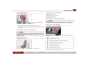 12
12 13
13 14
14 15
15 16
16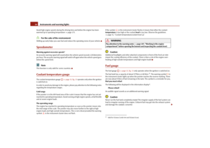 17
17 18
18 19
19 20
20 21
21 22
22 23
23 24
24 25
25 26
26 27
27 28
28 29
29 30
30 31
31 32
32 33
33 34
34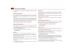 35
35 36
36 37
37 38
38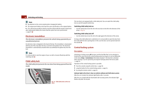 39
39 40
40 41
41 42
42 43
43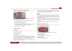 44
44 45
45 46
46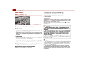 47
47 48
48 49
49 50
50 51
51 52
52 53
53 54
54 55
55 56
56 57
57 58
58 59
59 60
60 61
61 62
62 63
63 64
64 65
65 66
66 67
67 68
68 69
69 70
70 71
71 72
72 73
73 74
74 75
75 76
76 77
77 78
78 79
79 80
80 81
81 82
82 83
83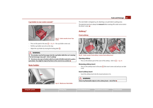 84
84 85
85 86
86 87
87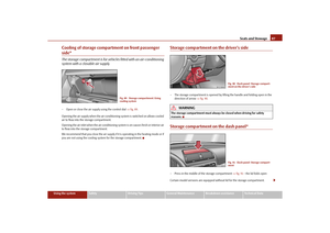 88
88 89
89 90
90 91
91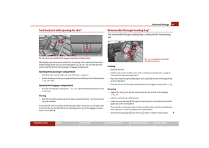 92
92 93
93 94
94 95
95 96
96 97
97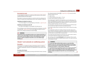 98
98 99
99 100
100 101
101 102
102 103
103 104
104 105
105 106
106 107
107 108
108 109
109 110
110 111
111 112
112 113
113 114
114 115
115 116
116 117
117 118
118 119
119 120
120 121
121 122
122 123
123 124
124 125
125 126
126 127
127 128
128 129
129 130
130 131
131 132
132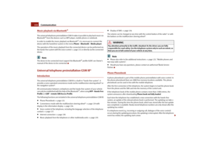 133
133 134
134 135
135 136
136 137
137 138
138 139
139 140
140 141
141 142
142 143
143 144
144 145
145 146
146 147
147 148
148 149
149 150
150 151
151 152
152 153
153 154
154 155
155 156
156 157
157 158
158 159
159 160
160 161
161 162
162 163
163 164
164 165
165 166
166 167
167 168
168 169
169 170
170 171
171 172
172 173
173 174
174 175
175 176
176 177
177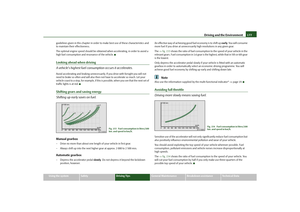 178
178 179
179 180
180 181
181 182
182 183
183 184
184 185
185 186
186 187
187 188
188 189
189 190
190 191
191 192
192 193
193 194
194 195
195 196
196 197
197 198
198 199
199 200
200 201
201 202
202 203
203 204
204 205
205 206
206 207
207 208
208 209
209 210
210 211
211 212
212 213
213 214
214 215
215 216
216 217
217 218
218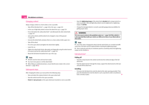 219
219 220
220 221
221 222
222 223
223 224
224 225
225 226
226 227
227 228
228 229
229 230
230 231
231 232
232 233
233 234
234 235
235 236
236 237
237 238
238 239
239 240
240 241
241 242
242 243
243 244
244 245
245 246
246 247
247 248
248 249
249 250
250 251
251 252
252 253
253 254
254 255
255 256
256 257
257 258
258 259
259 260
260 261
261 262
262 263
263 264
264 265
265 266
266 267
267 268
268 269
269 270
270 271
271 272
272 273
273 274
274