Page 233 of 275

Fuses and light bulbs
232
Turn signal light at the frontChanging light bulb for turn signal light (at the front)– Switch the ignition and all lights off.
– Remove the headlight page 231.
– Turn the socket in the direction of arrow OPEN and take it out together with the
light bulb for the turn signal light fig. 191 .
– Press the defective light bulb into the socket, turn to the left and remove.
– Press a new light bulb into the socket and turn the light bulb to the right as far as
the stop.
– Insert the socket with the changed light bulb into the headlight and secure it by turning in the direction of arrow CLOSE to the right.
Note
After installing the headlight, the headligh t setting must be checked by a specialist
garage.
Front parking lights and low beamRemoving the light bulb for the parking light– Switch the ignition and all lights off.
– Remove the headlight page 231.
– Remove the protective cap page 231, fig. 189.
– Remove the socket fig. 192 .
– Take the faulty bulb out of the fixture and insert a new one.
– Insert the protective cap.Removing the light bulb for the low beam light– Switch the ignition and all lights off.
– Remove the headlight page 231.
– Remove the protective cap page 231, fig. 189.
– Turn the connector with the light bulb up to the stop towards the left and
remove fig. 192 .
– Replace the lamp, insert the connector with the new lamp and turn to the right up to the stop.
– Insert the protective cap.
Fig. 191 Removing the light bulb for the
turn signal light
Fig. 192 Removing the bulbs for the
parking and low beam light
AB
AA
AB
AB
s43s.1.book Page 232 Thursday, May 13, 2010 1:21 PM
Page 234 of 275

Fuses and light bulbs233
Using the system
Safety
Driving Tips
General Maintenance
Breakdown assistance
Technical Data
Note
In order to facilitate the removal of the socket with the bulb for the parking light, we
recommend to remove first of all the bulb for the low beam light.
After installing the headlight, the headlight setting must be checked by a specialist
garage.
Main beam light– Switch the ignition and all lights off.
– Remove the headlight page 231.
– Remove the protective cap page 231, fig. 189 .
– Unplug plug fig. 193.
– Press the wire clamps in the directio n of the headlight and then unhook them
to the side.
– Remove the light bulb and insert the new light bulb in such a way that the fixing
lugs of the light bulb socket fit into the recesses at the reflector.
Installation takes place in the reverse order.
Note
After installing the headlight, the headligh t setting must be checked by a specialist
garage.
Fog lights and daylight driving lights*Fig. 194 Front bumper: Protective grille / removing the fog lightPlug - bulb for daylight driving lights* fig. 194 . Plug - bulb for fog lights.Removing the cover– Switch the ignition and all lights off.
– Guide the fingers into the opening fig. 194 .
– By pulling in the direction of arrow , first of all slacken the cover in the upper area on the side to the fog lights.
– Afterwards, also slacken the cover on th e other side in the direction of arrow
and remove it.Removing the fog light– Guide your hand into the opening, in which the cover was located, and press the
spring bolt fig. 194 - right.
– Take out the fog light.
– Turn the connector with the light bulb up to the stop towards the left and remove.
– Replace the lamp, insert the connector with the new lamp and turn to the right up to the stop.
– For the installation, first of all insert the fog light with the interlock to the side far away from the marking of the vehicle.
– Press into place the headlight on to the side facing the marking.
Fig. 193 Removing the light bulb for the
main beam light
AC
AA
ABAC
AB
AC
AAA1
A2
s43s.1.book Page 233 Thursday, May 13, 2010 1:21 PM
Page 235 of 275

Fuses and light bulbs
234
– In order to reinstall the cover, first of all insert one part of the cover starting on the
side facing the marking. Then press the cove r closed on the side facing the fog light.
The cover must engage firmly.Cover of fog lights Octavia RS, Octavia ScoutFig. 195 Front bumper: Octavia RS / Octavia ScoutRemoving the cover - Octavia RS– Switch the ignition and all lights off.
– Guide one finger into the opening fig. 195 and remove the cover.Removing the cover - Octavia Scout– Switch the ignition and all lights off.
– Guide the wire clamp from the vehicle tool kit into the opening above the fog
light and remove the cover.
Fog lights Octavia RS, Octavia ScoutFig. 196 Front bumper: Fog lights / fog lights: Replacing light bulbRemoving the fog light–Screw out the screws fig. 196 - left with the aid of the screwdriver*, which is part
of the vehicle tool kit
22).
– Take out the fog light.
Changing the bulb and installing the fog light– Press the locking button of the plug and remove the plug from the socket
.
– Turn the socket with the bulb to the left up to the stop and take it out.
– Change the bulb, insert again the socket wi th the new bulb and turn it to the right
up to the stop.
– Connect the plug to the socket .
– Screw in the screws again and insert the cover. The cover must engage firmly.
A1
A2
22)Valid for Octavia RS and Octavia Scout.
A1
AA
AB
ABAA
AB
s43s.1.book Page 234 Thursday, May 13, 2010 1:21 PM
Page 236 of 275

Fuses and light bulbs235
Using the system
Safety
Driving Tips
General Maintenance
Breakdown assistance
Technical Data
Light unit (Octavia)Fig. 197 Luggage compartment: Cover for th e lamp holder / removing the lamp holderChanging light bulbs in the lamp holder– Switch the ignition and all lights off.
– Unlock the locking button and open the cover of the lamp holder fig. 197 - left.
– Press the catches in the direction of arrow and take out the lamp holder fig. 197
- right.
– Press the defective light bulb into th e socket, turn to the left and remove.
– Press a new light bulb into the socket and turn the light bulb to the right as far as
the stop.
– Insert the lamp holder in such a way that the catches lock in place in the housing.
– Close and lock the cover of the lamp holder.Change the light bulb for the parking light– Switch the ignition and all lights off.
– Unlock the locking button and open the cover of the lamp holder fig. 197 - left.
– Take the defective light bulb (arrow or ) out of the housing and replace it with
a new one.
– Close and lock the cover of the lamp holder.
Rear light unit (Combi)Fig. 198 Luggage compartment: Side co mpartment / removing the lamp holderChanging light bulbs in the lamp holder– Switch the ignition and all lights off.
– Remove the side compartment cover by turning the locks in the direction of arrow
fig. 198 - left.
– Take out the cover of the lamp holder on the luggage compartment side.
– Take out the light bulbs of the tail light (arrow and ).
– Press the catches in the direction of arrow and take out the lamp holder.
– Press the defective light bulb into th e socket, turn to the left and remove.
– Press a new light bulb into the socket and turn the light bulb to the right as far as the stop.Change the light bulb for the parking light– Switch the ignition and all lights off.
– Remove the side compartment cover by turning the locks in the direction of arrow fig. 198 - left.
– Take out the cover of the lamp holder on the luggage compartment side.
– Take the defective light bulb (arrow or fig. 198 ) out of the housing and
replace it with a new one.
A1
A2
A1
A2
A1
A2
s43s.1.book Page 235 Thursday, May 13, 2010 1:21 PM
Page 237 of 275
Fuses and light bulbs
236
– Remove the lamp holder cover on the luggage compartment side and close the
side compartment.s43s.1.book Page 236 Thursday, May 13, 2010 1:21 PM
Page 238 of 275

Technical Data237
Using the system
Safety
Driving Tips
General Maintenance
Breakdown assistance
Technical Data
Te c h n i c a l D a t aTechnical DataGeneral informationThe details given in the official vehicle regi stration documents always take precedence
over the details in the Owner's Manual. Please refer to the official vehicle registration
documents or consult an authorised Škoda Service Partner concerning the engine with
which your vehicle is equipped.Used abbreviations
PerformancesThe listed performance values were de termined without performance-reducing
equipment, e.g. air conditioning system.WeightThe loading capacity is reduced in line with the range of the special equipment. The
unloaden weight contains a fuel tank topped up to 90%. A driver with a weight of 75
kg is also includ ed in the value.Identification details
Abbreviation
Importance
kW
Kilowatt, measuring unit for the engine output
rpm
Engine revolutions per minute
Nm
Newton meter, measuring unit for the engine torque
g/km
discharged quantity of carbon dioxide in grams per driven
kilometer
RON
Research octane number, meas uring unit for the knocking
resistance of petrol
TSI
Petrol engine with a turbocharger and a direct fuel injection
system
TDI PD
Diesel engine with turbocharg er and injection system unit
injector
TDI CR
Diesel engine with turbocharger and injection system Com-
mon Rail
M5 / M6
5-speed/6-speed manual gearbox
AG6
6-speed automatic gearbox
DQ6/DQ7
6 speed-/7 speed automatic gearbox DSG
DPF
Diesel particle filter
Abbreviation
Importance
Fig. 199 Vehicle data sticker
s43s.1.book Page 237 Thursday, May 13, 2010 1:21 PM
Page 239 of 275

Technical Data
238
Vehicle data sticker
The vehicle data sticker page 237, fig. 199 is located on the floor of the luggage
compartment and is also stated in the Service schedule.
The vehicle data sticker co ntains the following data:
Vehicle identifica tion number (VIN)
Vehicle type
Gearbox code, paint number, interior eq uipment number, engine output, engine
code
Partial description of the vehicle
7GG, 7MB, 7MG - vehicles with DPF page 173
Vehicle identification number (VIN)
The vehicle identification number - VIN (veh icle body number) is stamped into the
engine compartment on the right hand sh ock absorber dome. This number is also
located on a sign on the lower left hand edge below the windscreen.
Engine number
The engine number is stam ped into the engine block.
Type plate (production plate)
The type plate is located in the lowe r area of the left centre column.
Sticker on inside of fuel filler flap
The stickers are affixed to the inside of the fuel filler flap and contain the following
information:
The prescribed types of fuel,
Ty re s i z e ,
Tyre pressure.
Fuel consumption according to the ECE standards and EU guidelinesDepending on the range of the special equipment, style of driving, traffic situation,
weather influences an d vehicle condition, the consumpt ion values which in practice
result when using the vehicle can deviate from the indicated values.
Urban traffic
The consumption measurement in urban traffic begins with starting of the cold engine.
Afterwards the normal urban traffic is simulated.
Non-urban traffic
For the consumption measurement in non-ur ban traffic the vehicle, as in daily
motoring, is accelerated and braked severa l times in all gears. The vehicle speed
changes within the range from 0 to 120 km/h.
Combined traffic
The consumption value in the combined traffic consists of 37% from the value for the
urban traffic and of 63% from th e value for the non-urban traffic.
A1A2A3A4A5s43s.1.book Page 238 Thursday, May 13, 2010 1:21 PM
Page 240 of 275
Technical Data239
Using the system
Safety
Driving Tips
General Maintenance
Breakdown assistance
Technical Data
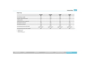
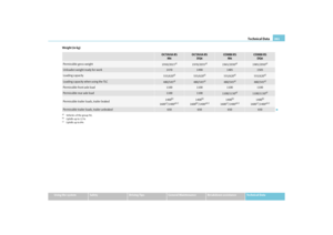
DimensionsDimensions (mm)
OCTAVIA
OCTAVIA
GreenLine
OCTAVIA RS
COMBI
COMBI
GreenLine
CO M B I R S
COMBI 4x4
SCOUT
Length
4569
4569
4597
4569
4569
4599
4569
4584
Width
1769
1769
1769
1769
1769
1769
1769
1784
Width including exterior mirror
2018
2018
2018
2018
2018
2018
2018
2018
Height
1462
1485
a)
1449
b)
a)The value corresponds to the status with rough road package.b)The value corresponds to the status with SPORT package.
1462
1449
b)
1447
1468
1490
a)
1455
b)
1468
1455
b)
1451
1495
1520
a)
1533
Clearance
140
164a)
125
b)
140
125b)
127
140
164a)
125
b)
140
125b)
128
138
163a)
179
Wheel base
2578
2578
2578
2578
2578
2578
2578
2578
Track gauge front / rear
1541/1514
1535/1508
1528/1508
1541/1514
1535/1508
1528/1508
1541/1514
1531/1500
s43s.1.book Page 239 Thursday, May 13, 2010 1:21 PM