Page 265 of 325

If and when263
Safety First
Operating Instructions
Practical Tips
Technical Specifications
•If you do come into contact with the sealant immediately rinse the eyes
or skin affected with clean water.•Change clothing immediately if it becomes soiled with the tyre sealant.•Make sure you do not breathe in the fumes!•If any of the tyre sealant is accidentally ingested, immediately rinse the
mouth thoroughly and drink lots of water.
−Do not induce vomiting. Seek medical assistance if needed.•If any allergic reactions should occur get medical help immediately.•Keep the sealant away from children.For the sake of the environment
If you have to dispose of a sealant can, go to a specialised waste ser vice or to
a SEAT Technical Service, where the product can be recycled in an appropriate
waste container.
Note
•If sealant should leak out, leave it to dry. When it has dried, you can pull
it off like a piece of foil.•Observe the expiry date stated on the sealing compound can. Have the
sealing compound exchanged by a qualified workshop.
Repairing a tyrePreparations
– If you have a flat tyre or puncture, park the vehicle as far away from the flow of traffic as possible.
–Apply the handbrake firmly to prevent the vehicle from moving
accidentally on slopes.
– Engage 1st gear .
– Check whether a repair is possibl e using the Tyre Mobility System
⇒ page 262.
– Ensure that all passengers leave the vehicle and move away from
the danger area ⇒ .
–Take the tyre sealant can and the compressor out of the luggage
compartment.
WARNING (continued)
Fig. 199 Repairing a tyre
ExeoST_EN.book Seite 263 Freitag, 3. September 2010 11:41 11
Page 266 of 325

If and when
264
– Stick the “max. 80 km/h” adhesive, which is included with the tyre sealant can, onto the instrument panel where the driver will
see it.
Filling the tyre
– Shake the tyre sealant can well.
– Screw the enclosed filling hose onto the sealant can as far as it will go. This will automatically pierce the foil sealing the can.
– Take the valve cap off the tyre valve and use the enclosed valve insert tool to unscrew the valve insert ⇒page 263, fig. 199 .
– Place the valve insert onto a clean surface.
– Remove the sealing plug from the filling hose and insert the hose into the tyre valve.
– Hold the tyre sealant can upside down and fill the complete contents of the can into the tyre.
– Then disconnect the hose and screw the valve insert firmly back into the tyre valve.
Inflating the tyre
– Screw the compressor filling hose onto the tyre valve and plug the connector into the cigarette lighter.
– Pump the tyre up to 2.0 to 2.5 bar and monitor the pressure shown on the pressure gauge. – If the tyre pressure remains lowe
r than the value specified above
drive the vehicle approx. 10 metres forwards or backwards, so
that the sealant can spread evenly in the tyre. If the pressure is
still lower than the specification the tyre is too badly damaged
and cannot be repaired using the tyre sealant.
Final check
– After about 10 minutes, stop to check the tyre pressure.
– If tyre pressure is less than 1.3 bar, the tyre is too badly damaged. Do not drive on! You should obtain professional
assistance.
WARNING
•If you have a puncture in heavy traffic, switch on the hazard warning
lights and place the warning triangle in a visible location. This is for your
own safety and also warns other road users.•Make su re your pass engers wait in a safe place ( for instance beh ind the
roadside crash barrier).•Please observe the manufacturer's safety notes on the compressor and
the instructions supplied with the tyre sealant can.•If it is not possible to build up a tyre pressure of 2.0 bar within 6
minutes this means that the tyre is too badly damaged. Do not drive on!•Seek professional assistance if the repair of a tyre puncture is not
possible with the sealing compound.•If tyre pressure is less than 1.3 bar after driving about 10 minutes, the
tyre is too badly damaged. Do not drive on! Obtain technical assistance.Caution
Take special care if you have to repair a tyre on a slope.
ExeoST_EN.book Seite 264 Freitag, 3. September 2010 11:41 11
Page 267 of 325

If and when265
Safety First
Operating Instructions
Practical Tips
Technical Specifications
Note
•Do not use the compressor for longer than 6 minutes. Otherwise, it might
overheat. When the compressor has cooled down, you can use it again.•If tyre sealant should leak out, leave it to dry and then pull it off like foil.•After carrying out a tyre repair remember to buy a new tyre sealant can at
a qualified workshop. This will ensure that the Tyre Mobility System is opera-
tive again.•Please observe legal requirements when doing so.FusesChanging fuses
If a fuse has blown, it must be replaced.
– Switch off the ignition and its failed electrical component.
– Remove the fuse cover using a screwdriver ⇒fig. 200 .
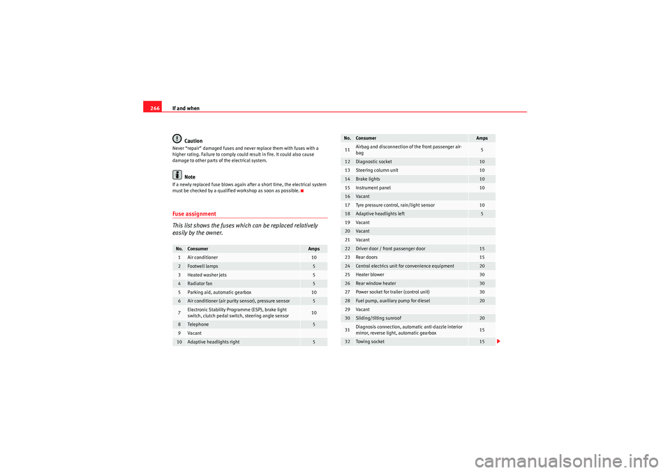
– Identify the fuse corresponding to the damaged electric consumer ⇒page 266, “Fuse assignment”.
– Take the plastic clip from inside the fuse cover, fit it onto the blown fuse, and pull the fuse out.
– Replace the blown fuse (which will have a melted metal strip) with a new fuse of the same amp rating.
–Fit the fuse cover back on.The individual electrical circuits are protected by fuses. The fuses are located
behind a cover at the left-hand end of the dash panel.
Two spare fuses and a sticker identifying the fuses are provided on the inside
of the fuse cover. There is also a crank handle for operating the sunroof* by
hand (if the electrical system fails).
Fig. 200 Left side of dash
panel: Fuse box cover
Fig. 201 Schematic
drawing of fuse box at the
left-hand end of dash
panel: Fuses (without fuse
cover)
ExeoST_EN.book Seite 265 Freitag, 3. September 2010 11:41 11
Page 268 of 325

If and when
266
CautionNever “repair” damaged fuses and never replace them with fuses with a
higher rating. Failure to comply could result in fire. It could also cause
damage to other parts of the electrical system.
Note
If a newly replaced fuse blows again after a short time, the electrical system
must be checked by a qualified workshop as soon as possible.Fuse assignment
This list shows the fuses which can be replaced relatively
easily by the owner.No.
Consumer
Amps
1
Air conditioner
10
2
Footwell lamps
5
3
Heated washer jets
5
4
Radiator fan
5
5
Parking aid, automatic gearbox
10
6
Air conditioner (air purity sensor), pressure sensor
5
7
Electronic Stability Programme (ESP), brake light
switch, clutch pedal switch, steering angle sensor
10
8
Tele ph one
5
9
Va can t
10
Adaptive headlights right
5
11
Airbag and disconnection of the front passenger air-
bag
5
12
Diagnostic socket
10
13
Steering column unit
10
14
Brake lights
10
15
Instrument panel
10
16
Va can t
17
Tyre pressure control, rain/light sensor
10
18
Adaptive headlights left
5
19
Va can t
20
Va can t
21
Va can t
22
Driver door / front passenger door
15
23
Rear doors
15
24
Central electrics unit for convenience equipment
20
25
Heater blower
30
26
Rear window heater
30
27
Power socket for trailer (control unit)
30
28
Fuel pump, auxiliary pump for diesel
20
29
Va can t
30
Sliding/tilting sunroof
20
31
Diagnosis connection, automatic anti-dazzle interior
mirror, reverse light, automatic gearbox
15
32
Towing socket
15
No.
Consumer
Amps
ExeoST_EN.book Seite 266 Freitag, 3. September 2010 11:41 11
Page 269 of 325

If and when267
Safety First
Operating Instructions
Practical Tips
Technical Specifications
Some of the electrical items listed in the table are only fitted on certain
models or are optional extras.
The electric windows and electric seat adjusters are protected by circuit
breakers
. These reset automatically after a few seconds when the overload
(caused for example by frozen windows) has been corrected.
Note
Please note that the above list contains all data at the time of going to press,
so it is subject to modifications. If discrepancies should occur, please refer to
the sticker on the inside of the fuse cover for the correct information for your
model.
BulbsGeneral informationYou can change the following bulbs for exterior lights yourself:•Main headlights: all bulbs (except xenon headlights)•Tail lights: all bulbs•Side turn signal bulb
The following bulbs can only be changed by a qualified workshop:•Main headlights: Xenon* bulb ⇒page 274•Front fog light bulbs
As a rule, you require a certain degree of practical skill to change defective
bulbs. This applies in particular to those bulbs which are only accessible from
the engine compartment.
If in doubt, we recommend that you have defective bulbs changed by a qual-
ified workshop or qualified mechanic.
If you do decide to change bulbs in the engine compartment yourself, be
aware of the safety risks involved ⇒page 229 ⇒ in “Types of bulbs”.Changing bulbs. Halogen headlightsTypes of bulbsYou must only replace a bulb with a bulb of the same type. The name can be
found on the base of the bulb holder.
33
Lighter
20
34
Lambda probe heater
5
35
Luggage compartment power socket*
20
36
Wiper system
30
37
Pump for windscreen washer and headlight washer
system
30
38
Luggage compartment illumination, alarm
15
39
Radio, amplifier
20
40
Horn
25
41
230 volt socket
30
42
Electronic Stability Programme (ESP)
25
43
Engine management
15
44
Seat heating
35
No.
Consumer
Amps
ExeoST_EN.book Seite 267 Freitag, 3. September 2010 11:41 11
Page 270 of 325

If and when
268
WARNING
•Take particular care when working on components in the engine
compartment if the engine is warm - risk of burns!•Bulbs are highly sensitive to pressure. The glass can break when you
touch the bulb, causing injury.•The high voltage element of gas discha rge bulbs* (xenon light) must be
handled correctly. Otherwise, there is a risk of death.•When changing bulbs, please take care not to injure yourself on sharp
parts in the headlight housing.Caution
•Remove the ignition key before working on the electric system. If not, a
short circuit could occur.•Switch off the lights or parking lights before you change a bulb.For the sake of the environment
Please ask your specialist retailer how to dispose of used bulbs in the proper
manner.
Note
•Depending on weather conditions (cold or wet), the front lights, the fog
lights, the tail lights and the turn signals may be temporarily misted. This has no influence on the useful life of the lighting system. By switching on the
lights, the area through which the beam of light is projected will quickly be
demisted. However, the edges may continue to be misted.
•Please check at regular intervals that all lighting (especially the exterior
lighting) on your vehicle is functioning properly. This is not only in the interest
of your own safety, but also in that of all other road users.•Before changing a bulb, make sure you have the correct new bulb.•Do not touch the glass part of the bulb with your bare hands, use a cloth
or paper towel instead. Otherwise, the fingerprints left on the glass will
vaporise as a result of the heat generated by the bulb, be deposited on the
reflector and impair its surface.Removing the air duct
The air duct has to be removed to gain access to the bulbs for
the right-side headlight.
Bulb
Type
Dipped beam headlights (halogen)
12 V/55 W (H7 LL)
Main beam headlights
12 V/55 W (H1)
Turn signal
12 V/21 W (PY21W)
Side lights
12 V/5 W (W5W LL)
Fig. 202 Air duct on right
side of vehicle
ExeoST_EN.book Seite 268 Freitag, 3. September 2010 11:41 11
Page 271 of 325
If and when269
Safety First
Operating Instructions
Practical Tips
Technical Specifications
–Unscrew bolts ⇒ page 268, fig. 202.
– Detach air duct from guide and take it out.Fitting the air duct
Once the bulb(s) for the right-side headlight have been
changed, the air duct must be re-installed.– Place the air duct in the correct position.
– First turn the two screws in lightly, then tighten both screws.
– Push the air duct into guide .
Halogen headlight bulbs
Main beam headlights
Side lights
Dipped beam headlights
Side lights
Turn signal
AA
AB
Fig. 203 Air duct on right
side of vehicle
AAAB
Fig. 204 Halogen bulbs
AAABACADAE
ExeoST_EN.book Seite 269 Freitag, 3. September 2010 11:41 11
Page 272 of 325
If and when
270Changing the turn signal bulb
The procedure for changing the bulb is the same on both
sides.– Switch off the ignition and the lights.
– Raise the bonnet.
– Turn the bulb holder anti-clockwise, pulling it by the grip
⇒fig. 205 and removing the bulb holder and the bulb.
– Replace the blown bulb in the bulb holder (press and turn anti- clockwise to remove) with a new bulb (press and turn clockwise
to insert).
– Installation is done in the reverse order.
– Check whether the new bulb is working. Note
Although it is not necessary, previously remove the rigid cover
⇒page 272,
fig. 208 for easier turn signal bulb changes.
Fig. 205 Turn signal
ExeoST_EN.book Seite 270 Freitag, 3. September 2010 11:41 11