Page 4 of 230
PETROL INJECTION
Fault finding - Introduction
17B-4
17B
PETROL INJECTION
Fault finding - Introduction
17B-4
17B
V9 MR-372-J84-17B050$047.mif
S3000 Injection
Program No.: AD
Vdiag No.: 4C / 54
4. FAULT FINDING PROCEDURE
Check the battery charge and
condition of the fuses
Print the system fault finding log
(available on CLIP and in the
Workshop Repair Manual or
Technical Note)
Connect CLIP
no
Dialogue with
computer?
yes
Read the faults
no
Faults present
yes
Deal with present faults
Deal with stored faults
no
The cause is still
presentFault
solved
yes
See ALP 1
Conformity check
no
The cause is still
presentFault
solved
yes
Use Fault Finding Charts (ALPs)
no
The cause is still
presentFault
solved
yes
Contact Techline with the
completed fault finding log
Page 130 of 230

PETROL INJECTION
Fault finding - Conformity check
17B
17B-130
PETROL INJECTION
Fault finding - Conformity check
17B
17B-130V9 MR-372-J84-17B050$470.mif
S3000 Injection
Program No.: AD
Vdiag No.: 4C / 54
SUB-FUNCTION: DRIVER PARAMETERS (continued 1):
NOTESOnly check the conformity after a complete check with the diagnostic tool. The values
shown in this conformity check are given as a guide.
Application conditions: Engine off, ignition on.
Order FunctionParameter or Status Checked
or ActionDisplay and notes Fault finding
10Accelerator
pedal and
motorised
throttleET075:Pedal released and
throttle closedYESIf NO, apply the
interpretation for
PR030 Accelerator
pedal position
followed by the
interpretation for fault
DF079 Motorised
throttle valve servo
control.
11
Motorised
throttlePR597:Motorised throttle in
safe mode15% < PR597 < 25%Run command
RZ005
Programming. If the
parameters or
statuses are still not
correct, contact the
Techline. 12 PR593:Motorised throttle in
safe mode gang 1PR593 ≈ 1 V
13 PR594:Motorised throttle in
safe mode gang 2PR594 ≈ 1 V
14Accelerator
pedalET081:Accelerator pedal
positionNo load
Full load
INTERMEDIATEIn the event of a fault
apply the
interpretation for
PR030 Accelerator
pedal position
15Accelerator
pedalPR030:Accelerator pedal
positionNo load = < 16%
PF ≥85%In the event of a fault,
apply interpretation of
DF196 and DF198
Pedal sensor circuit
gangs 1 and 2, then
DF011 and DF012
Sensor supply
voltage 1 and 2.
Page 218 of 230
PETROL INJECTION
Fault finding - Test
17B
17B-218
PETROL INJECTION
Fault finding - Test
17B
17B-218V9 MR-372-J84-17B050$846.mif
S3000 Injection
Program No.: AD
Vdiag No.: 4C / 54PETROL INJECTION
Fault finding - Test
TEST 2: Camshaft dephaser solenoid valve. (Vdiag 4C)
TEST 3: Camshaft dephaser solenoid valve. (Vdiag 54)
NOTESOnly refer to these tests when dealing with a fault finding chart (ALP) following
a customer complaint, or during the interpretation of one or more faults.
MR-372-J84-17B050$846.mif
Page 223 of 230
PETROL INJECTION
Fault finding - Customer complaints
17B
17B-223
PETROL INJECTION
Fault finding - Customer complaints
17B
17B-223V9 MR-372-J84-17B050$893.mif
S3000 Injection
Program No.: AD
Vdiag No.: 4C / 54PETROL INJECTION
Fault finding - Customer complaints
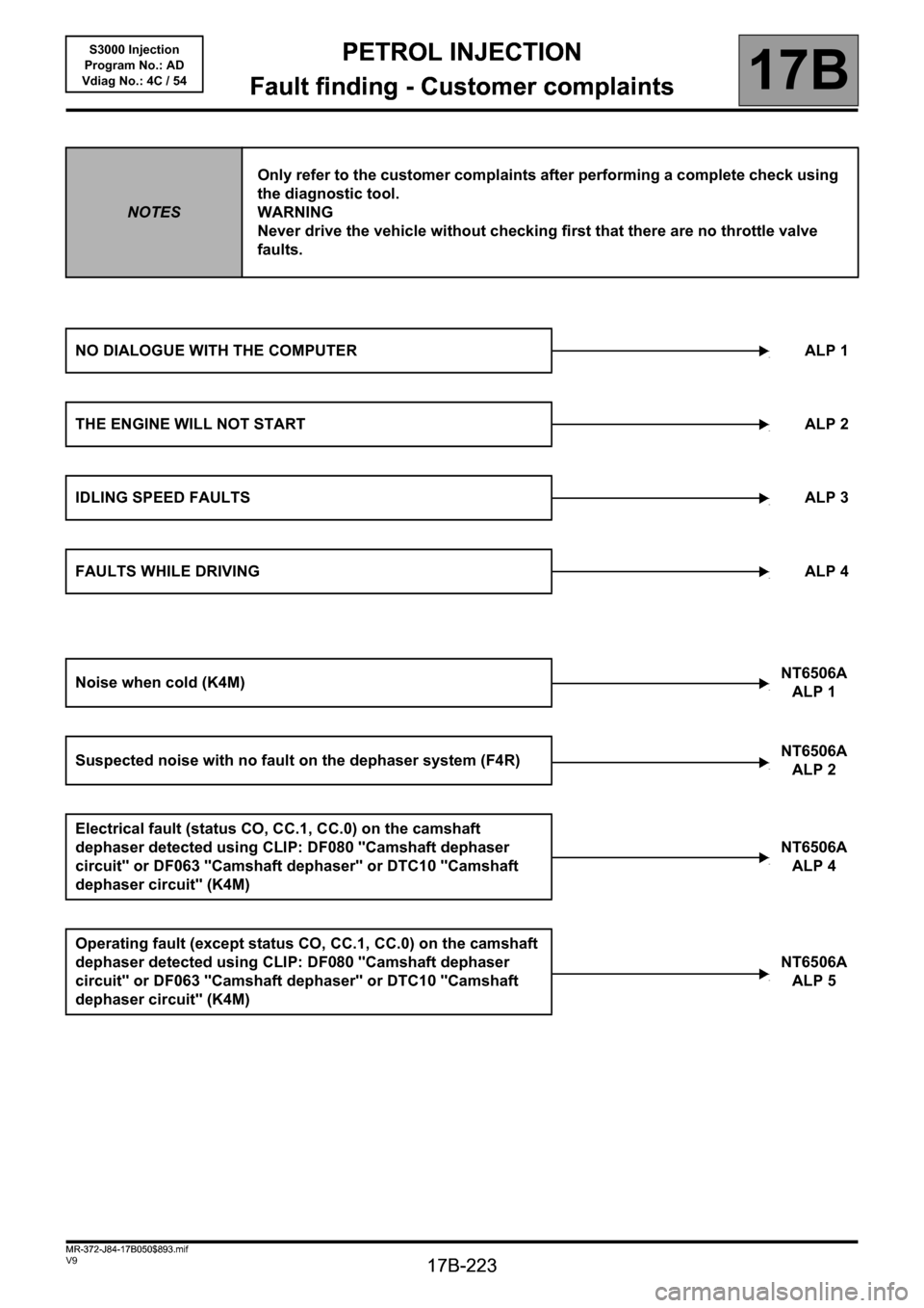
NOTESOnly refer to the customer complaints after performing a complete check using
the diagnostic tool.
WARNING
Never drive the vehicle without checking first that there are no throttle valve
faults.
NO DIALOGUE WITH THE COMPUTER ALP 1
THE ENGINE WILL NOT STARTALP 2
IDLING SPEED FAULTSALP 3
FAULTS WHILE DRIVINGALP 4
Noise when cold (K4M)NT6506A
ALP 1
Suspected noise with no fault on the dephaser system (F4R)NT6506A
ALP 2
Electrical fault (status CO, CC.1, CC.0) on the camshaft
dephaser detected using CLIP: DF080 "Camshaft dephaser
circuit" or DF063 "Camshaft dephaser" or DTC10 "Camshaft
dephaser circuit" (K4M)NT6506A
ALP 4
Operating fault (except status CO, CC.1, CC.0) on the camshaft
dephaser detected using CLIP: DF080 "Camshaft dephaser
circuit" or DF063 "Camshaft dephaser" or DTC10 "Camshaft
dephaser circuit" (K4M) NT6506A
ALP 5
MR-372-J84-17B050$893.mif
Page 224 of 230
PETROL INJECTION
Fault finding - Customer complaints
17B
17B-224
PETROL INJECTION
Fault finding - Customer complaints
17B
17B-224V9 MR-372-J84-17B050$893.mif
S3000 Injection
Program No.: AD
Vdiag No.: 4C / 54
Camshaft dephaser fault detected using CLIP: DF080 "Camshaft
dephaser circuit" or DF063 "Camshaft dephaser"
or DTC10 "Camshaft dephaser circuit" (F4R) NT6506A
ALP 6
Oil leak from the camshaft dephaserNT6506A
ALP 7
Oil leak from the camshaft dephaser solenoid valveNT6506A
ALP 8
Page 225 of 230

PETROL INJECTION
Fault finding - Fault Finding Chart
17B
17B-225
PETROL INJECTION
Fault finding - Fault Finding Chart
17B
17B-225V9 MR-372-J84-17B050$940.mif
S3000 Injection
Program No.: AD
Vdiag No.:4C / 54PETROL INJECTION
Fault finding - Fault Finding Chart
ALP 1 No dialogue with the computer
NOTESNone.
Test the diagnostic tool on another vehicle which is in perfect working order.
Check that the sensor's green indicator light comes on.
If you cannot establish dialogue with the second vehicle, refer to CLIP diagnostic tool check.
If there is no dialogue with the second vehicle, follow the instructions in the Vehicle check section.
CLIP
DIAGNOSTIC
TOOL CHECK
VEHICLE CHECK
Check the cleanliness and condition of the diagnostic socket contacts which connect
to the vehicle.
Check the condition of the cable from the diagnostic socket to the sensor, and the
cleanliness and condition of the connections.
Check the sensor connections.
Check the condition of the cable from the sensor to the CLIP tool, and the cleanliness
and condition of the connections.
Check the cleanliness and condition of the CLIP socket.
If the fault is still present, contact the Techline.
Check the electrical voltage of the battery.
Check the cleanliness and condition of the battery terminals.
Check the condition and tightness of the cable going from the battery + terminal to the
Protection and Switching Unit.
Check the condition of the battery earth lead and that it makes good electrical contact
with the bodywork.
Check the injection computer earth terminal for cleanliness and make sure it is properly
connected to the bodywork.
Check the injection computer after ignition feed 5A fuse F18 as well as the condition
and cleanliness of the contacts.
AFTER REPAIRRepeat the conformity check from the start.
S3000_V4C_ALP1/S3000_V54_ALP1
MR-372-J84-17B050$940.mif
Page 226 of 230

PETROL INJECTION
Fault finding - Fault Finding Chart
17B
17B-226
PETROL INJECTION
Fault finding - Fault Finding Chart
17B
17B-226V9 MR-372-J84-17B050$940.mif
S3000 Injection
Program No.: AD
Vdiag No.:4C / 54
ALP 1
CONTINUED 1
VEHICLE CHECK
CONTINUED 1Using the Universal bornier, check the following tracks on the vehicle's diagnostic
socket:
Track 1 + After ignition feed
Track 16 + battery feed
Tracks 4 and 5 Earth
Repair if necessary.
Disconnect the battery and the petrol computer.
Check the cleanliness and condition of the computer connections.
Using the Universal bornier, check the continuity of the multiplex line
communication lines:
Computer, connector A, track A4 track 6 Vehicle diagnostic socket
Computer, connector A, track A3 track 14 Vehicle diagnostic socket
If the fault is still present, check the condition of intermediate connector R262.
Repair if necessary.
Check the continuity of the K communication line:
Computer, connector A, track B4 track 7 of the vehicle diagnostic
socket
If the fault is still present, check the condition of the intermediate connector (R262).
Repair if necessary.
Disconnect the computer earth terminal connection from the negative battery terminal.
Check the continuity and insulation of the following tracks:
Petrol computer, connectorC,
track L1Earth terminal
Fuel computer, connectorC,
track M1Earth terminal
Petrol computer, connectorB,
track M1Earth terminal
Petrol computer, connectorB,
track L1Earth terminal
Repair if necessary.
AFTER REPAIRRepeat the conformity check from the start.
Page 227 of 230
PETROL INJECTION
Fault finding - Fault Finding Chart
17B
17B-227
PETROL INJECTION
Fault finding - Fault Finding Chart
17B
17B-227V9 MR-372-J84-17B050$940.mif
S3000 Injection
Program No.: AD
Vdiag No.:4C / 54
ALP 1
CONTINUED 2
VEHICLE CHECK
CONTINUED 2Using the universal bornier, check for insulation and continuity on the following
connection:
Computer, connectorB, track D4 track 5 of the main relay
Repair if necessary.
Using the Universal bornier, check for continuity on the following connection:
Computer, connectorB, track M2 track 1 of the main relay
Repair if necessary.
Check the condition and operation of fuse F6 (10A).
Using the Universal bornier, check for continuity on the following connection:
Computer, connector A, track D1 track 8 of the fuse box
Fuse box track8 track1 of the petrol pump relay
Repair if necessary.
If the fault is still present, contact the Techline.
AFTER REPAIRRepeat the conformity check from the start.


