2010 RENAULT SCENIC air condition
[x] Cancel search: air conditionPage 181 of 230

PETROL INJECTION
Fault finding - Interpretation of statuses
17B
17B - 181
PETROL INJECTION
Fault finding - Interpretation of statuses
17B
17B - 181V9 MR-372-J84-17B050$611.mif
S3000 Injection
Program No.: AD
Vdiag No.: 4C / 54
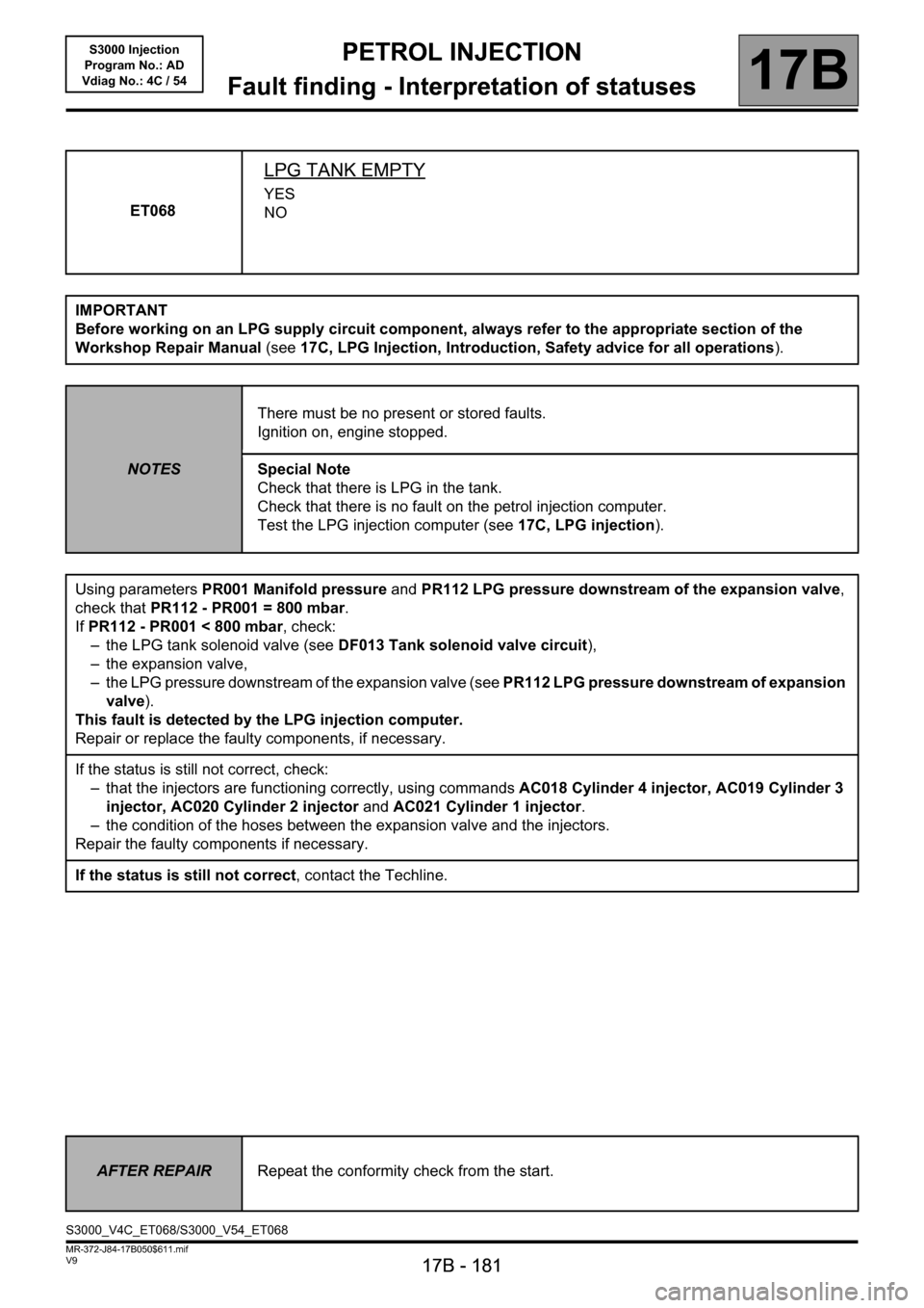
ET068
LPG TANK EMPTY
YES
NO
IMPORTANT
Before working on an LPG supply circuit component, always refer to the appropriate section of the
Workshop Repair Manual (see17C, LPG Injection, Introduction, Safety advice for all operations).
NOTESThere must be no present or stored faults.
Ignition on, engine stopped.
Special Note
Check that there is LPG in the tank.
Check that there is no fault on the petrol injection computer.
Test the LPG injection computer (see17C, LPG injection).
Using parameters PR001 Manifold pressure and PR112 LPG pressure downstream of the expansion valve,
check that PR112 - PR001 = 800 mbar.
If PR112 - PR001 < 800 mbar, check:
– the LPG tank solenoid valve (see DF013 Tank solenoid valve circuit),
– the expansion valve,
– the LPG pressure downstream of the expansion valve (see PR112 LPG pressure downstream of expansion
valve).
This fault is detected by the LPG injection computer.
Repair or replace the faulty components, if necessary.
If the status is still not correct, check:
– that the injectors are functioning correctly, using commands AC018 Cylinder 4 injector, AC019 Cylinder 3
injector, AC020 Cylinder 2 injector and AC021 Cylinder 1 injector.
– the condition of the hoses between the expansion valve and the injectors.
Repair the faulty components if necessary.
If the status is still not correct, contact the Techline.
AFTER REPAIRRepeat the conformity check from the start.
S3000_V4C_ET068/S3000_V54_ET068
Page 184 of 230

PETROL INJECTION
Fault finding - Interpretation of statuses
17B
17B - 184
PETROL INJECTION
Fault finding - Interpretation of statuses
17B
17B - 184V9 MR-372-J84-17B050$611.mif
S3000 Injection
Program No.: AD
Vdiag No.: 4C / 54
ET073
CONDITIONS FOR SWITCHING TO LPG MODE
AUTHORISED
INHIBITED
IMPORTANT
Before working on an LPG supply circuit component, always refer to the appropriate section of the
Workshop Repair Manual (see17C, LPG Injection, Introduction, Safety advice for all operations).
NOTESThere must be no present or stored faults.
Ignition on, engine stopped.
Variable duration depending on:
–ET100 LPG system ready,
–PR002 Coolant temperature,
–PR103 Air temperature,
–PR113 LPG temperature.
Apply the interpretation of faults DF103 LPG expansion valve solenoid valve and DF007 Main relay circuit.
These faults are detected by the LPG injection computer.
Manipulate the wiring harness between the LPG computer and the petrol computer until a change in status is
noted.
Check the insulation, continuity and ensure the absence of interference resistance on the connections
between:
Petrol computer connectorB, track K3 track A1 of the LPG computer
Petrol computer connectorB, track K4 track A2 of the LPG computer
Repair if necessary.
If the status is still not correct, contact the Techline.
AFTER REPAIRRepeat the conformity check from the start.
S3000_V4C_ET073/S3000_V54_ET073
Page 185 of 230

PETROL INJECTION
Fault finding - Interpretation of statuses
17B
17B - 185
PETROL INJECTION
Fault finding - Interpretation of statuses
17B
17B - 185V9 MR-372-J84-17B050$611.mif
S3000 Injection
Program No.: AD
Vdiag No.: 4C / 54
ET405
CLUTCH PEDAL SWITCH
NOTESSpecial note:
Only perform the tests if the statuses do not correspond with the system programming
functions.
ACTIVECheck the condition and fitting of the clutch pedal switch.
Remove the clutch pedal switch then check the insulation between tracks 1 and 2, with
the switch in the rest position.
Repeat this operation with the switch pressed and check the continuity between tracks
1 and 2.
If these two checks are not in order, replace the switch.
INACTIVECheck the condition and fitting of the clutch pedal switch.
Remove the clutch pedal switch then check the insulation between tracks 1 and 2, with
the switch in the rest position.
Repeat this operation with the switch pressed and check the continuity between tracks
1 and 2.
If these two checks are not in order, replace the switch.
Then check the continuity and make sure there is no interference resistance
on the following connection:
Injection computer connector A, black, 32-track, track C4 Track 1 clutch
connector
Check for earth on track 2 of the clutch switch connector.
If there is a repair method (see Technical Note 6015A, Electrical wiring repair,
Wiring: Repair precautions), repair the wiring, otherwise replace it.
AFTER REPAIRDeal with any other faults. Clear the fault memory.
Switch off the ignition and carry out a road test followed by a test with the diagnostic
tool.
S3000_V4C_ET405/S3000_V54_ET405
Page 191 of 230

PETROL INJECTION
Fault finding - Interpretation of statuses
17B
17B - 191
PETROL INJECTION
Fault finding - Interpretation of statuses
17B
17B - 191V9 MR-372-J84-17B050$611.mif
S3000 Injection
Program No.: AD
Vdiag No.: 4C / 54
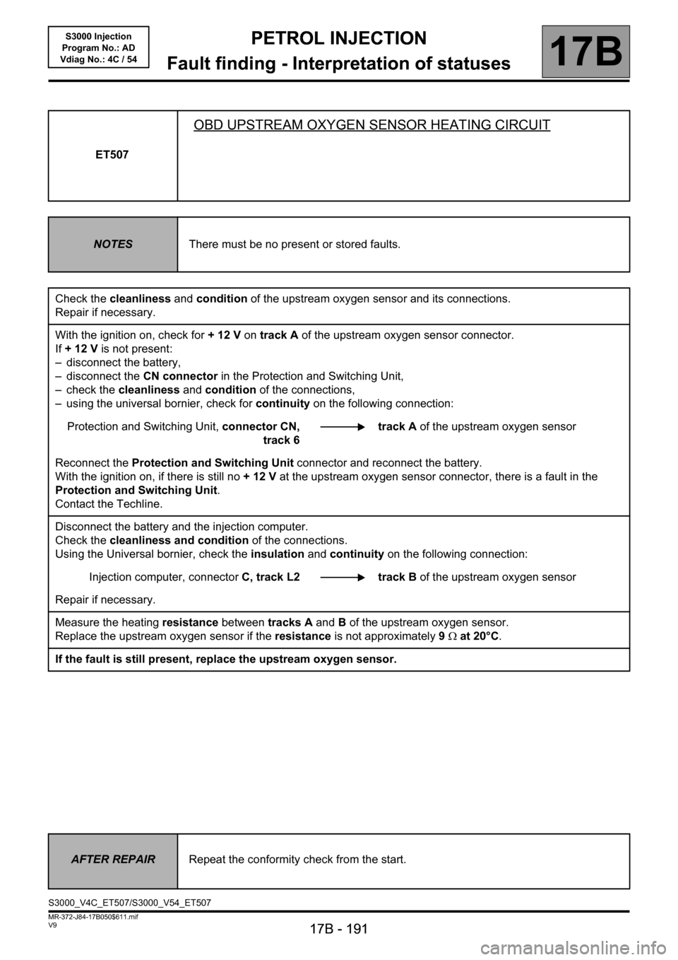
ET507
OBD UPSTREAM OXYGEN SENSOR HEATING CIRCUIT
NOTESThere must be no present or stored faults.
Check the cleanliness and condition of the upstream oxygen sensor and its connections.
Repair if necessary.
With the ignition on, check for + 12 V on track A of the upstream oxygen sensor connector.
If +12V is not present:
– disconnect the battery,
– disconnect the CN connector in the Protection and Switching Unit,
– check the cleanliness and condition of the connections,
– using the universal bornier, check for continuity on the following connection:
Protection and Switching Unit, connector CN,
track 6track A of the upstream oxygen sensor
Reconnect the Protection and Switching Unit connector and reconnect the battery.
With the ignition on, if there is still no +12V at the upstream oxygen sensor connector, there is a fault in the
Protection and Switching Unit.
Contact the Techline.
Disconnect the battery and the injection computer.
Check the cleanliness and condition of the connections.
Using the Universal bornier, check the insulation and continuity on the following connection:
Injection computer, connectorC, track L2 track B of the upstream oxygen sensor
Repair if necessary.
Measure the heating resistance between tracks A and B of the upstream oxygen sensor.
Replace the upstream oxygen sensor if the resistance is not approximately 9Ω at 20°C.
If the fault is still present, replace the upstream oxygen sensor.
AFTER REPAIRRepeat the conformity check from the start.
S3000_V4C_ET507/S3000_V54_ET507
Page 192 of 230

PETROL INJECTION
Fault finding - Interpretation of statuses
17B
17B - 192
PETROL INJECTION
Fault finding - Interpretation of statuses
17B
17B - 192V9 MR-372-J84-17B050$611.mif
S3000 Injection
Program No.: AD
Vdiag No.: 4C / 54
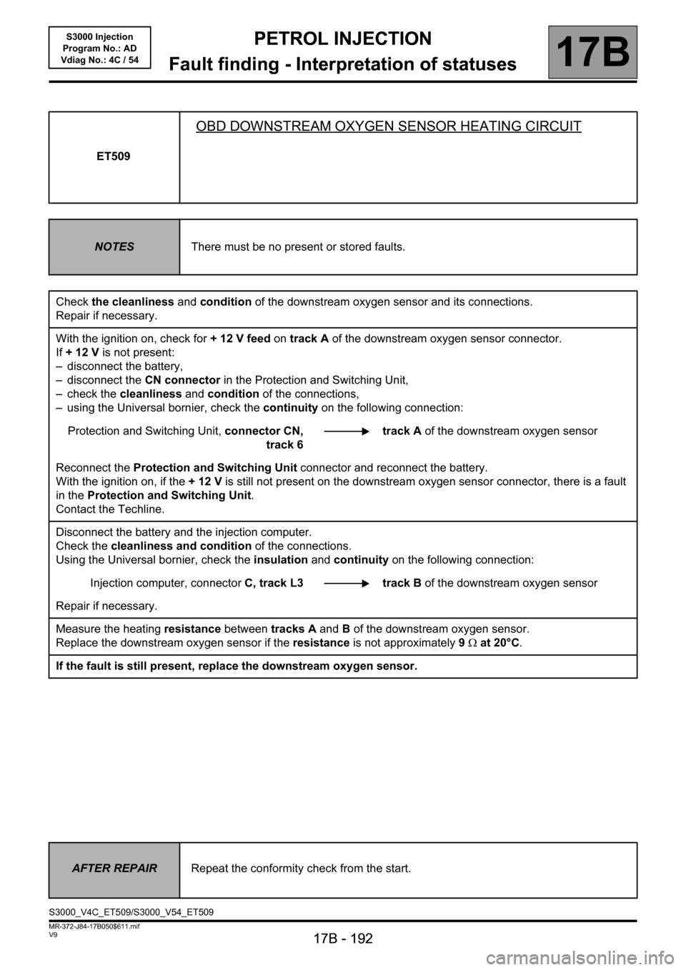
ET509
OBD DOWNSTREAM OXYGEN SENSOR HEATING CIRCUIT
NOTESThere must be no present or stored faults.
Check the cleanliness and condition of the downstream oxygen sensor and its connections.
Repair if necessary.
With the ignition on, check for + 12 V feed on track A of the downstream oxygen sensor connector.
If +12V is not present:
– disconnect the battery,
– disconnect the CN connector in the Protection and Switching Unit,
– check the cleanliness and condition of the connections,
– using the Universal bornier, check the continuity on the following connection:
Protection and Switching Unit, connector CN,
track 6track A of the downstream oxygen sensor
Reconnect the Protection and Switching Unit connector and reconnect the battery.
With the ignition on, if the +12V is still not present on the downstream oxygen sensor connector, there is a fault
in the Protection and Switching Unit.
Contact the Techline.
Disconnect the battery and the injection computer.
Check the cleanliness and condition of the connections.
Using the Universal bornier, check the insulation and continuity on the following connection:
Injection computer, connectorC, track L3 track B of the downstream oxygen sensor
Repair if necessary.
Measure the heating resistance between tracks A and B of the downstream oxygen sensor.
Replace the downstream oxygen sensor if the resistance is not approximately 9Ω at 20°C.
If the fault is still present, replace the downstream oxygen sensor.
AFTER REPAIRRepeat the conformity check from the start.
S3000_V4C_ET509/S3000_V54_ET509
Page 198 of 230

PETROL INJECTION
Fault finding - Interpretation of statuses
17B
17B - 198
PETROL INJECTION
Fault finding - Interpretation of statuses
17B
17B - 198V9 MR-372-J84-17B050$611.mif
S3000 Injection
Program No.: AD
Vdiag No.: 4C / 54
ET703
CRUISE CONTROL/SPEED LIMITER BUTTONS
NOTESSpecial notes:
Only perform the tests if the statuses do not correspond with the system programming
functions.
INACTIVEStatus ET703 becomes "INACTIVE" when none of the cruise control/speed limiter
buttons is pressed. These buttons are located on the steering wheel.
If status ET703 does not display "INACTIVE",
●check the condition of the cruise control/speed limiter +/- button and the condition of
its connector,
●check the condition of the cruise control/speed limiter R/0 button and the condition of
its connector.
INCREASEStatus ET703 becomes PLUS when the cruise control/speed limiter + button is pressed.
This button is on the steering wheel, on the left-hand side.
If status ET703 does not display PLUS, check the condition of the cruise control/speed
limiter +/- button, and the condition of its connector. Repair if necessary.
To carry out these checks and measurements in complete safety, observe the
recommendations for removing the driver's front airbag (see MR 364 Mechanical, 88C,
Airbag and seat belt pretensioners, Driver's front airbag, Removal - Refitting)
Measure the resistance on the following connection with the "+" button pressed:
Injection computer,
connector A, black, 32-track track D2 "+/-" button track 2.
connector A, black, 32-track track D3 "+/-" button track 1.
If the resistance is not approximately 300 Ω, check the continuity of the connection when
the button is not pressed.
If there is continuity, replace the +/- control button.
If there is a repair procedure (see Technical Note 6015A, Repairing electrical wiring,
Wiring: Precautions for repair), repair the wiring, otherwise replace it.
AFTER REPAIRDeal with any other faults. Clear the fault memory.
Switch off the ignition and carry out a road test followed by a test with the diagnostic
tool.
S3000_V4C_ET703/S3000_V54_ET703
Page 199 of 230

PETROL INJECTION
Fault finding - Interpretation of statuses
17B
17B - 199
PETROL INJECTION
Fault finding - Interpretation of statuses
17B
17B - 199V9 MR-372-J84-17B050$611.mif
S3000 Injection
Program No.: AD
Vdiag No.: 4C / 54
ET703
CONTINUED 1
DECREASEStatus ET703 becomes MINUS when the cruise control/speed limiter - button is pressed.
This button is on the steering wheel, on the left-hand side.
If status ET703 does not change to MINUS, check the condition of the cruise control/
speed limiter "+/-" button, and the condition of its connector. Repair if necessary.
To carry out these checks and measurements in complete safety, observe the
recommendations for removing the driver's front airbag (see MR 364 Mechanical, 88C,
Airbag and pretensioners, Driver's front airbag, Removal - Refitting).
Measure the resistance on the following connection with the "-" button pressed:
Injection computer,
connector A, black, 32-track track D2 "+/-" button track 2.
connector A, black, 32-track track D3 "+/-" button track 1.
If the resistance is not approximately 100Ω, check the continuity of the connection when
the button is not pressed.
If there is continuity, replace the "+/-" control button.
If there is a repair procedure (see Technical Note 6015A, Repairing electrical wiring,
Wiring: Precautions for repair), repair the wiring, otherwise replace it.
RESUMEStatus ET703 becomes RESUME when the cruise control/speed limiter R button is
pressed. This button is located on the steering wheel, to the right.
If status ET703 does not change to RESUME, check the condition of the cruise control/
speed limiter R/0 button, and the condition of its connector. Repair if necessary.
To carry out these checks and measurements in complete safety, observe the
recommendations for removing the driver's front airbag (see MR 364 Mechanical, 88C,
Airbag and pretensioners, Driver's front airbag, Removal - Refitting)
Measure the resistance of the following connection with the "R" button pressed:
Injection computer,
connector A, black, 32-track track D2 "+/-" button track 2.
connector A, black, 32-track track D3 "+/-" button track 1.
If the resistance is not approximately 900 Ω, check the continuity of the connection when
the button is not pressed.
If there is continuity, replace the "R/0" control button.
If there is a repair procedure (see Technical Note 6015A, Repairing electrical wiring,
Wiring: Precautions for repair), repair the wiring, otherwise replace it.
AFTER REPAIRDeal with any other faults. Clear the fault memory.
Switch off the ignition and carry out a road test followed by a test with the diagnostic
tool.
Page 200 of 230

PETROL INJECTION
Fault finding - Interpretation of statuses
17B
17B - 200
PETROL INJECTION
Fault finding - Interpretation of statuses
17B
17B - 200V9 MR-372-J84-17B050$611.mif
S3000 Injection
Program No.: AD
Vdiag No.: 4C / 54
ET703
CONTINUED 2
SUSPENDStatus ET703 becomes SUSPEND when the cruise control/speed limiter 0 button is
pressed. This button is located on the steering wheel, to the right.
If status ET703 does not change to SUSPEND, check the condition of the cruise control/
speed limiter R/0 button, and the condition of its connector.
To carry out these checks and measurements in complete safety, observe the
recommendations for removing the driver's front airbag (see MR 364 Mechanical, 88C,
Airbag and pretensioners, Driver's front airbag, Removal - Refitting)
Measure the resistance of the following connection with the "0" button pressed:
Injection computer,
connector A, black, 32-track track D2 "+/-" button track 2.
connector A, black, 32-track track D3 "+/-" button track 1.
If the resistance is not approximately 0 Ω, replace the R/0 control button.
If there is continuity, replace the "R/0" control button.
If there is a repair procedure (see Technical Note 6015A, Repairing electrical wiring,
Wiring: Precautions for repair), repair the wiring, otherwise replace it.
AFTER REPAIRDeal with any other faults. Clear the fault memory.
Switch off the ignition and carry out a road test followed by a test with the diagnostic
tool.