Page 190 of 230

PETROL INJECTION
Fault finding - Interpretation of statuses
17B
17B - 190
PETROL INJECTION
Fault finding - Interpretation of statuses
17B
17B - 190V9 MR-372-J84-17B050$611.mif
S3000 Injection
Program No.: AD
Vdiag No.: 4C / 54
ET415
(CONTINUED 4)
STATUS 10Monitoring by injection computer
Status ET415 becomes STATUS 10 when driving with cruise control active (ET042
Cruise control/speed limiter: CRUISE CONTROL) and if the injection computer
detects a fault anywhere in the engine management system, or an engine speed that is
too high or too low.
This signal is conveyed on the multiplex line and deactivates the cruise control.
Carry out a multiplex network test, then run fault finding on the injection computer.
Deal with any present or stored faults (see Interpretation of faults).
Reinitialise status ET415 on the injection computer by running command RZ001
"Fault memory".
If status 10 continues, contact the Techline.
AFTER REPAIRDeal with any other faults. Clear the fault memory.
Switch off the ignition and carry out a road test followed by a test with the diagnostic
tool.
Page 191 of 230

PETROL INJECTION
Fault finding - Interpretation of statuses
17B
17B - 191
PETROL INJECTION
Fault finding - Interpretation of statuses
17B
17B - 191V9 MR-372-J84-17B050$611.mif
S3000 Injection
Program No.: AD
Vdiag No.: 4C / 54
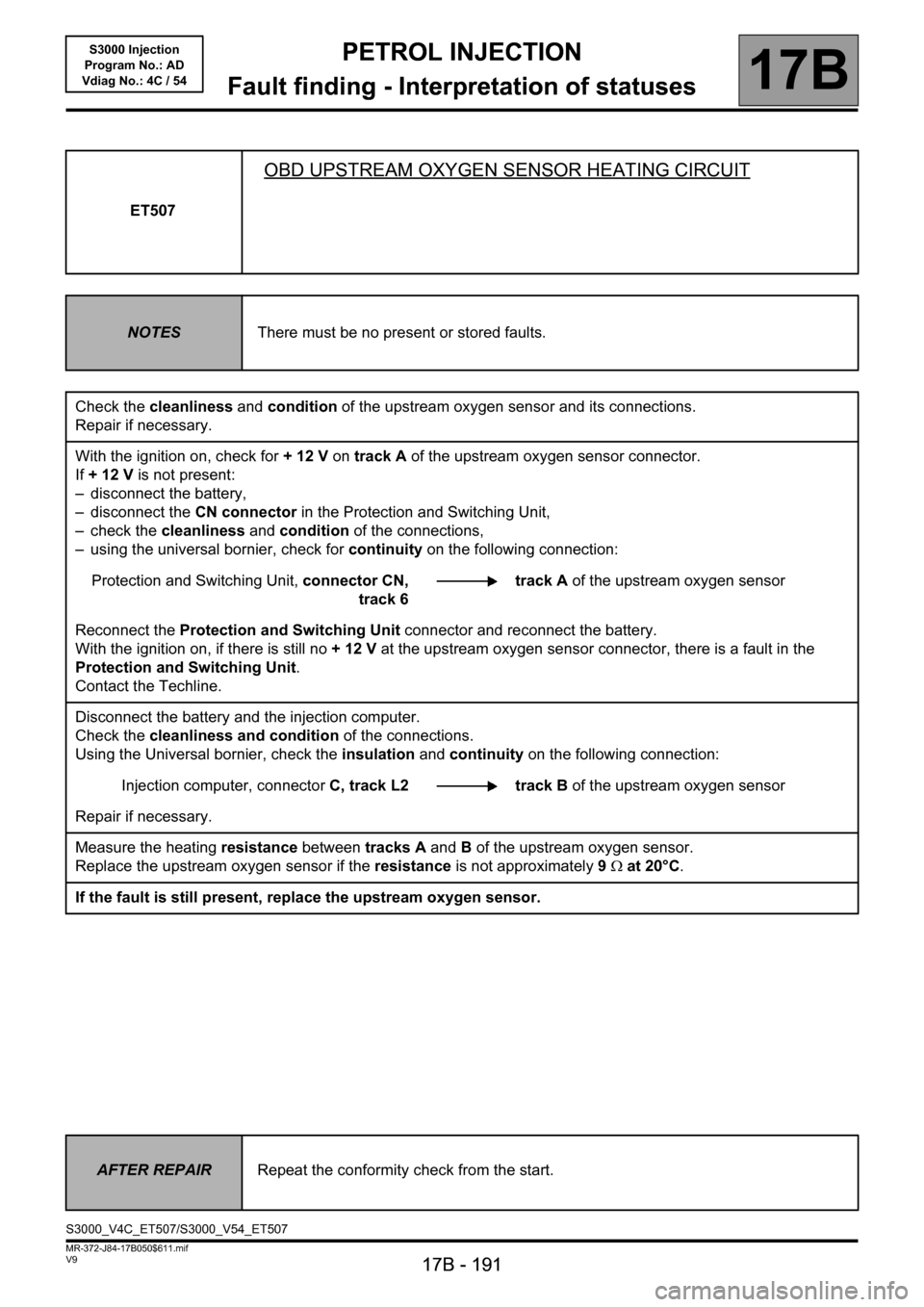
ET507
OBD UPSTREAM OXYGEN SENSOR HEATING CIRCUIT
NOTESThere must be no present or stored faults.
Check the cleanliness and condition of the upstream oxygen sensor and its connections.
Repair if necessary.
With the ignition on, check for + 12 V on track A of the upstream oxygen sensor connector.
If +12V is not present:
– disconnect the battery,
– disconnect the CN connector in the Protection and Switching Unit,
– check the cleanliness and condition of the connections,
– using the universal bornier, check for continuity on the following connection:
Protection and Switching Unit, connector CN,
track 6track A of the upstream oxygen sensor
Reconnect the Protection and Switching Unit connector and reconnect the battery.
With the ignition on, if there is still no +12V at the upstream oxygen sensor connector, there is a fault in the
Protection and Switching Unit.
Contact the Techline.
Disconnect the battery and the injection computer.
Check the cleanliness and condition of the connections.
Using the Universal bornier, check the insulation and continuity on the following connection:
Injection computer, connectorC, track L2 track B of the upstream oxygen sensor
Repair if necessary.
Measure the heating resistance between tracks A and B of the upstream oxygen sensor.
Replace the upstream oxygen sensor if the resistance is not approximately 9Ω at 20°C.
If the fault is still present, replace the upstream oxygen sensor.
AFTER REPAIRRepeat the conformity check from the start.
S3000_V4C_ET507/S3000_V54_ET507
Page 192 of 230

PETROL INJECTION
Fault finding - Interpretation of statuses
17B
17B - 192
PETROL INJECTION
Fault finding - Interpretation of statuses
17B
17B - 192V9 MR-372-J84-17B050$611.mif
S3000 Injection
Program No.: AD
Vdiag No.: 4C / 54
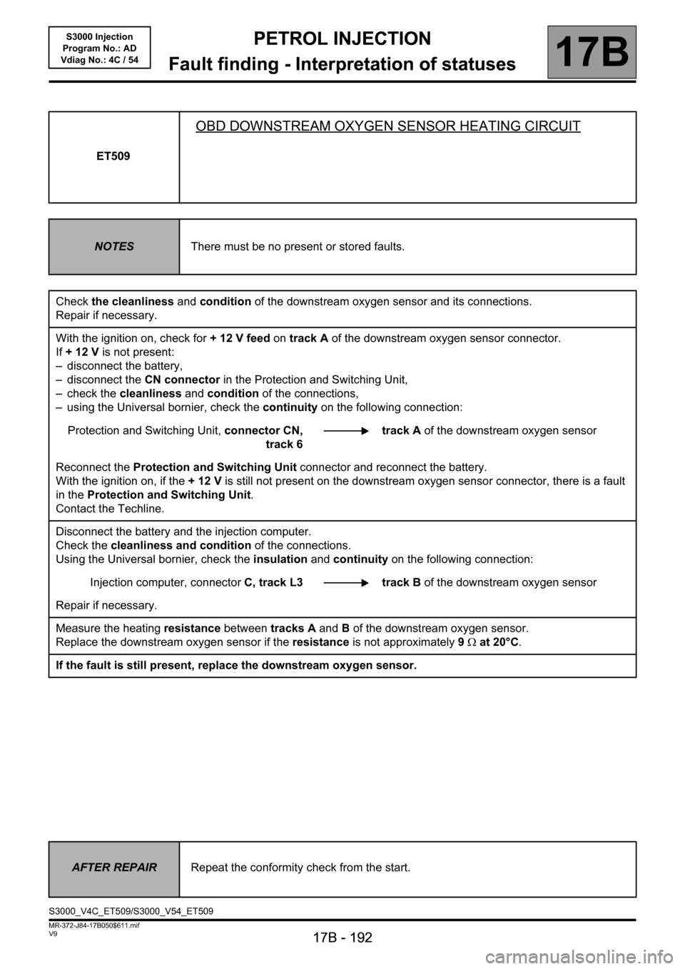
ET509
OBD DOWNSTREAM OXYGEN SENSOR HEATING CIRCUIT
NOTESThere must be no present or stored faults.
Check the cleanliness and condition of the downstream oxygen sensor and its connections.
Repair if necessary.
With the ignition on, check for + 12 V feed on track A of the downstream oxygen sensor connector.
If +12V is not present:
– disconnect the battery,
– disconnect the CN connector in the Protection and Switching Unit,
– check the cleanliness and condition of the connections,
– using the Universal bornier, check the continuity on the following connection:
Protection and Switching Unit, connector CN,
track 6track A of the downstream oxygen sensor
Reconnect the Protection and Switching Unit connector and reconnect the battery.
With the ignition on, if the +12V is still not present on the downstream oxygen sensor connector, there is a fault
in the Protection and Switching Unit.
Contact the Techline.
Disconnect the battery and the injection computer.
Check the cleanliness and condition of the connections.
Using the Universal bornier, check the insulation and continuity on the following connection:
Injection computer, connectorC, track L3 track B of the downstream oxygen sensor
Repair if necessary.
Measure the heating resistance between tracks A and B of the downstream oxygen sensor.
Replace the downstream oxygen sensor if the resistance is not approximately 9Ω at 20°C.
If the fault is still present, replace the downstream oxygen sensor.
AFTER REPAIRRepeat the conformity check from the start.
S3000_V4C_ET509/S3000_V54_ET509
Page 193 of 230
PETROL INJECTION
Fault finding - Interpretation of statuses
17B
17B - 193
PETROL INJECTION
Fault finding - Interpretation of statuses
17B
17B - 193V9 MR-372-J84-17B050$611.mif
S3000 Injection
Program No.: AD
Vdiag No.: 4C / 54
ET564
DEFECT MODE TYPE 1
NOTESThere must be no present or stored faults.
This status covers faults that disable control of the motorised throttle valve.
This defect mode cuts off the throttle control (mechanical Limp Home position).
AFTER REPAIRRepeat the conformity check from the start.
S3000_V4C_ET564/S3000_V54_ET564
Page 194 of 230
PETROL INJECTION
Fault finding - Interpretation of statuses
17B
17B - 194
PETROL INJECTION
Fault finding - Interpretation of statuses
17B
17B - 194V9 MR-372-J84-17B050$611.mif
S3000 Injection
Program No.: AD
Vdiag No.: 4C / 54
ET565
TYPE 2 DEFECT MODE
NOTESThere must be no present or stored faults.
This status covers faults where the system has lost control of the air flow modulation. The associated defect mode
limits the engine speed through injection cut-off.
AFTER REPAIRRepeat the conformity check from the start.
S3000_V4C_ET565/S3000_V54_ET565
Page 195 of 230
PETROL INJECTION
Fault finding - Interpretation of statuses
17B
17B - 195
PETROL INJECTION
Fault finding - Interpretation of statuses
17B
17B - 195V9 MR-372-J84-17B050$611.mif
S3000 Injection
Program No.: AD
Vdiag No.: 4C / 54
ET566
TYPE 3 DEFECT MODE
NOTESThere must be no present or stored faults.
This status groups the faults for deducing that the system no longer responds to engine or vehicle speed regulation,
but still controls the air flow modulation (throttle servo system operational). It uses the pedal mode reconstructed
by calibration.
AFTER REPAIRRepeat the conformity check from the start.
S3000_V4C_ET566/S3000_V54_ET566
Page 196 of 230
PETROL INJECTION
Fault finding - Interpretation of statuses
17B
17B - 196
PETROL INJECTION
Fault finding - Interpretation of statuses
17B
17B - 196V9 MR-372-J84-17B050$611.mif
S3000 Injection
Program No.: AD
Vdiag No.: 4C / 54
ET567
TYPE 4 DEFECT MODE
NOTESThere must be no present or stored faults.
This status covers faults affecting the monitoring system, or for which there is an emergency operating mode viable
for the system (scenario of falling back on the second gang of a pedal or throttle potentiometer if there is a fault on
the main gang).
Its effect is to restrict the throttle (limited performance).
AFTER REPAIRRepeat the conformity check from the start.
S3000_V4C_ET567/S3000_V54_ET567
Page 197 of 230
PETROL INJECTION
Fault finding - Interpretation of statuses
17B
17B - 197
PETROL INJECTION
Fault finding - Interpretation of statuses
17B
17B - 197V9 MR-372-J84-17B050$611.mif
S3000 Injection
Program No.: AD
Vdiag No.: 4C / 54
ET568
TYPE 5 DEFECT MODE
NOTESThere must be no present or stored faults.
This status covers faults affecting the control of the throttle by the torque structure. Its effect is to use the pedal
feedback mode, instead of the permanent torque structure.
AFTER REPAIRRepeat the conformity check from the start.
S3000_V4C_ET568/S3000_V54_ET568