2010 NISSAN TIIDA specifications
[x] Cancel search: specificationsPage 4 of 3745
2010
QUICK REFERENCE CHART: VERSA
QUICK REFERENCE CHART: VERSA
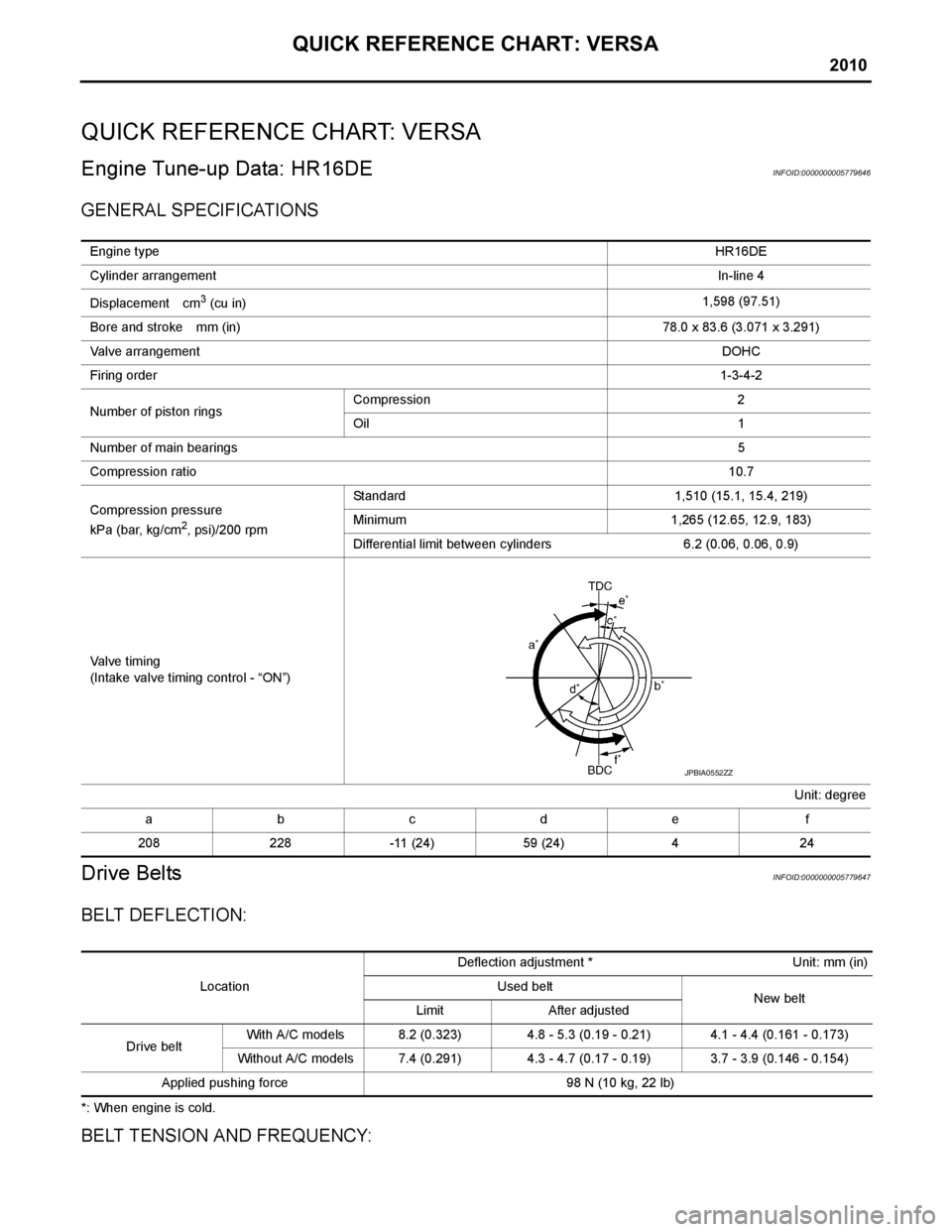
Engine Tune-up Data: HR16DEINFOID:0000000005779646
GENERAL SPECIFICATIONS
Drive BeltsINFOID:0000000005779647
BELT DEFLECTION:
*: When engine is cold.
BELT TENSION AND FREQUENCY:
Engine typeHR16DE
Cylinder arrangement In-line 4
Displacement cm
3 (cu in) 1,598 (97.51)
Bore and stroke mm (in) 78.0 x 83.6 (3.071 x 3.291)
Valve arrangement DOHC
Firing order 1-3-4-2
Number of piston rings Compression 2
Oil 1
Number of main bearings 5
Compression ratio 10.7
Compression pressure
kPa (bar, kg/cm
2, psi)/200 rpm Standard 1,510 (15.1, 15.4, 219)
Minimum 1,265 (12.65, 12.9, 183)
Differential limit between cylinders 6.2 (0.06, 0.06, 0.9)
Valve timing
(Intake valve timing control - “ON”) Unit: degree
abcde f
208 228 -11 (24) 59 (24) 4 24
JPBIA0552ZZ
Location Deflection adjustment * Unit: mm (in)
Used belt New belt
Limit After adjusted
Drive belt With A/C models 8.2 (0.323) 4.8 - 5.3 (0.19 - 0.21) 4.1 - 4.4 (0.161 - 0.173)
Without A/C models 7.4 (0.291) 4.3 - 4.7 (0.17 - 0.19) 3.7 - 3.9 (0.146 - 0.154)
Applied pushing force 98 N (10 kg, 22 lb)
Page 5 of 3745

QUICK REFERENCE CHART: VERSA
2010
*: When engine is cold.
Spark PlugINFOID:0000000005779648
SPARK PLUG
Unit: mm (in)
*: Always check with the Parts Department for the latest parts information
Engine Tune-up Data: MR18DEINFOID:0000000005779645
GENERAL SPECIFICATIONS
DRIVE BELT
SPARK PLUG
Unit: mm (in)
*: Always check with the Parts Department for the latest parts informationLocation
Tension adjustment * Unit: N (kg, lb) Frequency adjustment * Unit: Hz
Used belt New beltUsed belt
New belt
Limit After adjusted Limit After adjusted
Drive belt With A/C models 500 (51.0, 112)
876 - 964
(89.4 - 98.3,
197 - 217)1064 - 1152
(108.5 - 117.5,
239 - 259)
173 229 - 239 253.5 - 261.5
Without A/C models 500 (51.0, 112) 876 - 964
(89.4 - 98.3, 197 - 217) 1064 - 1152
(108.5 - 117.5, 239 - 259) 194 257.5 - 267.5 283 - 293
Make
Denso
Standard type* FXE20HE-11
Gap (Nominal) 1.1 (0.043)
Engine type MR18DE
Cylinder arrangement In-line 4
Displacement cm
3 (cu in)1,797 (109.65)
Bore and stroke mm (in) 84.0 x 81.1 (3.307 x 3.192)
Valve arrangement DOHC
Firing order 1-3-4-2
Number of piston rings Compression 2
Oil 1
Compression ratio 9.9
Compression pressure
kPa (bar, kg/cm
2, psi) / 250 rpm Standard 1,500 (15.0, 15.3, 217.6)
Minimum 1,200 (12.0, 12.2, 174)
Differential limit between cylinders 100 (1.0, 1.0, 15)
Tension of drive belt Auto adjustment by auto-tensioner
Make
DENSO
Standard type* FXE20HR11
Spark plug gap Nominal: 1.1 (0.043)
Page 21 of 3745

AT-4
Transmission Range Switch ..................................225
Output Speed Sensor ............................................227
Input Speed Sensor ...............................................228
Differential Side Oil Seal ........................................229
AIR BREATHER HOSE ...................................232
Removal and Installation ..................................... ..232
TRANSAXLE ASSEMBLY ..............................233
Removal and Installation ..................................... ..233
OVERHAUL .................................................... .237
Component .......................................................... ..237
Oil Channel ............................................................250
Location of Adjusting Shims, Needle Bearings and
Thrust Washers .....................................................
253
Location of Snap Rings .........................................255
DISASSEMBLY .............................................. .257
Disassembly ........................................................ ..257
REPAIR FOR COMPONENT PARTS ..............275
Manual Shaft ....................................................... ..275
Oil Pump ................................................................278
Control Valve Assembly ........................................281
Control Valve Upper Body .....................................290
Control Valve Lower Body ................................... ..294
Reverse Clutch ......................................................297
High Clutch ............................................................302
Forward and Overrun Clutches .............................307
Low & Reverse Brake ............................................314
Rear Internal Gear and Forward Clutch Hub .........318
Output Shaft, Output Gear, Idler Gear, Reduction
Pinion Gear and Bearing Retainer .........................
322
Band Servo Piston Assembly ................................331
Final Drive .............................................................337
ASSEMBLY .....................................................344
Assembly (1) ........................................................ ..344
Adjustment (1) (For HR16DE Engine Models) ..... .345
Adjustment (1) (For MR18DE Engine Models) .....349
Assembly (2) .........................................................355
Adjustment (2) .......................................................360
Assembly (3) .........................................................363
SERVICE DATA AND SPECIFICATIONS
(SDS) ................................................................
373
General Specification ........................................... .373
Vehicle Speed at Which Gear Shifting Occurs .....373
Vehicle Speed at When Lock-up Occurs/Releases
.
373
Stall Speed ............................................................374
Line Pressure ........................................................374
Adjusting shims, Needle Bearings, Thrust Wash-
ers and Snap Rings ..............................................
374
Control Valves .......................................................375
Accumulator ..........................................................376
Clutches and Brakes .............................................376
Final Drive .............................................................378
Planetary Carrier ...................................................378
Oil Pump ...............................................................378
Input Shaft .............................................................378
Reduction Pinion Gear ..........................................378
Band Servo ...........................................................378
Output Shaft ..........................................................379
Bearing Retainer ...................................................379
Total End Play ...................................................... .379
Reverse Clutch End Play ......................................379
Removal and Installation .......................................379
Shift Solenoid Valves ........................................... .379
Solenoid Valves ....................................................380
A/T Fluid Temperature Sensor ..............................380
Output Speed Sensor ...........................................380
Dropping Resistor .................................................380
Input Speed Sensor ..............................................380
Revision: January 20102010 Versa
Page 69 of 3745
AT-52
< SERVICE INFORMATION >
TROUBLE DIAGNOSIS
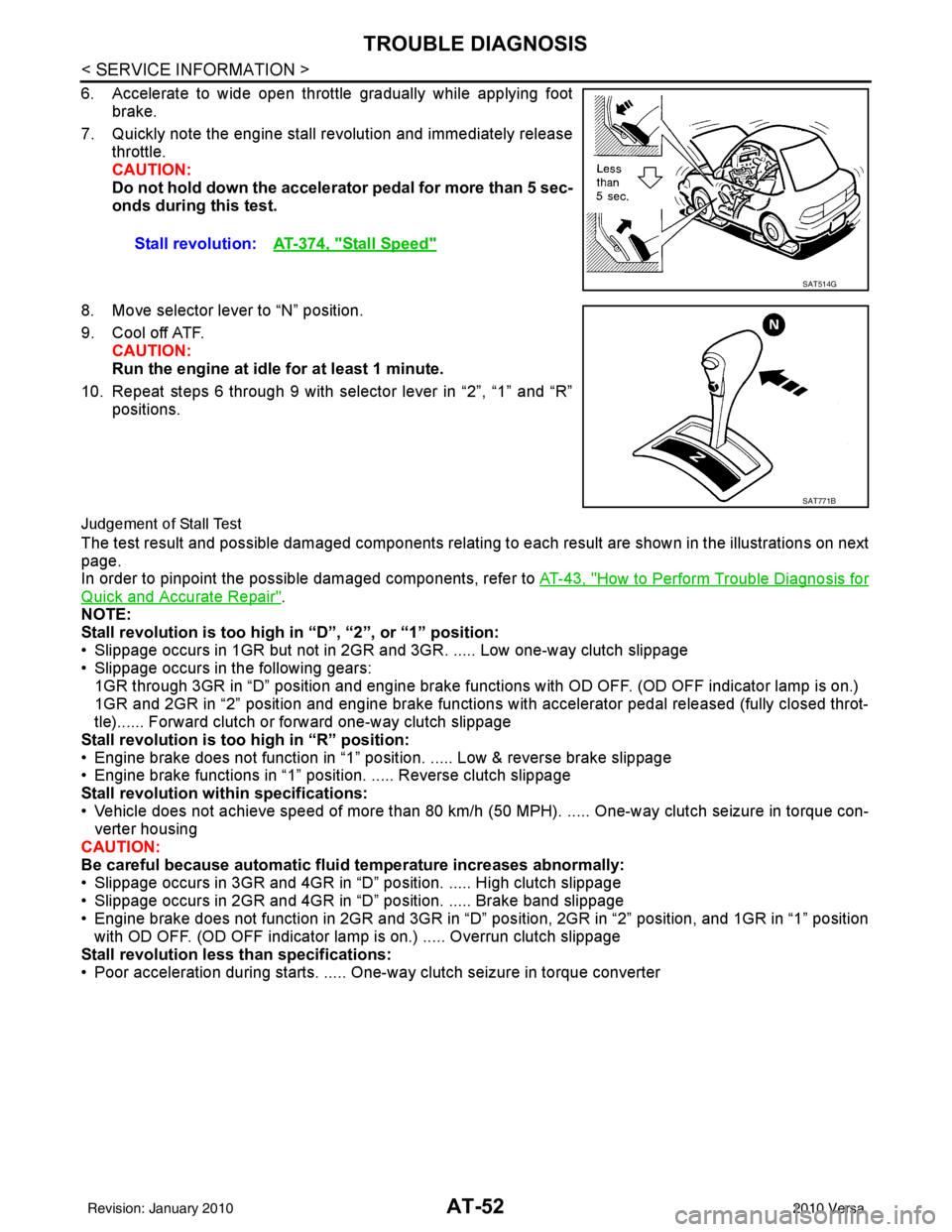
6. Accelerate to wide open throttle gradually while applying footbrake.
7. Quickly note the engine stall revolution and immediately release throttle.
CAUTION:
Do not hold down the accelerator pedal for more than 5 sec-
onds during this test.
8. Move selector lever to “N” position.
9. Cool off ATF. CAUTION:
Run the engine at idle for at least 1 minute.
10. Repeat steps 6 through 9 with selector lever in “2”, “1” and “R” positions.
Judgement of Stall Test
The test result and possible damaged components relating to each result are shown in the illustrations on next
page.
In order to pinpoint the possible damaged components, refer to AT-43, "
How to Perform Trouble Diagnosis for
Quick and Accurate Repair".
NOTE:
Stall revolution is too high in “D”, “2”, or “1” position:
• Slippage occurs in 1GR but not in 2GR and 3GR. ..... Low one-way clutch slippage
• Slippage occurs in the following gears:
1GR through 3GR in “D” position and engine brake functions with OD OFF. (OD OFF indicator lamp is on.)
1GR and 2GR in “2” position and engine brake functions with accelerator pedal released (fully closed throt-
tle)...... Forward clutch or forward one-way clutch slippage
Stall revolution is too high in “R” position:
• Engine brake does not function in “1” posit ion. ..... Low & reverse brake slippage
• Engine brake functions in “1” position. ..... Reverse clutch slippage
Stall revolution within specifications:
• Vehicle does not achieve speed of more than 80 km/h ( 50 MPH). ..... One-way clutch seizure in torque con-
verter housing
CAUTION:
Be careful because automatic flui d temperature increases abnormally:
• Slippage occurs in 3GR and 4GR in “D” position. ..... High clutch slippage
• Slippage occurs in 2GR and 4GR in “D” position. ..... Brake band slippage
• Engine brake does not function in 2GR and 3GR in “D” pos ition, 2GR in “2” position, and 1GR in “1” position
with OD OFF. (OD OFF indicator lamp is on.) ..... Overrun clutch slippage
Stall revolution less than specifications:
• Poor acceleration during starts. ..... One-way clutch seizure in torque converter Stall revolution:
AT-374, "
Stall Speed"
SAT514G
SAT771B
Revision: January 20102010 Versa
Page 297 of 3745
AT-280
< SERVICE INFORMATION >
REPAIR FOR COMPONENT PARTS
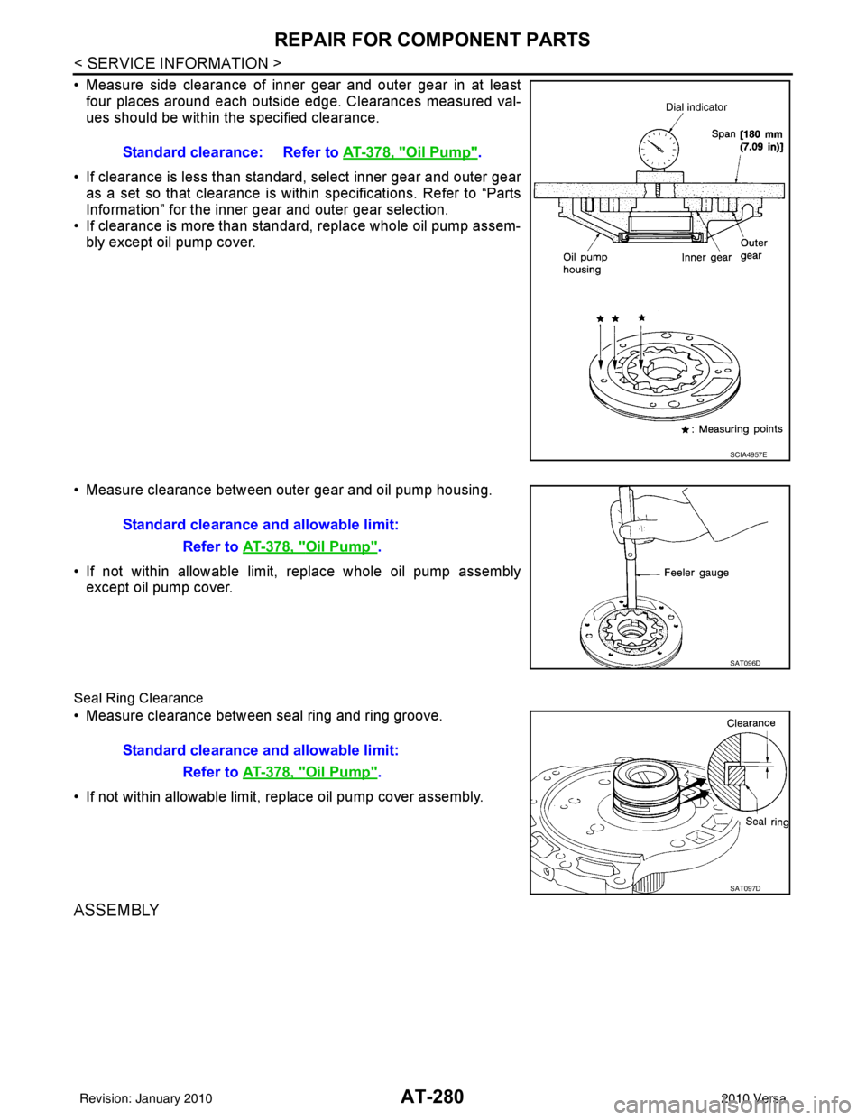
• Measure side clearance of inner gear and outer gear in at leastfour places around each outside edge. Clearances measured val-
ues should be within the specified clearance.
• If clearance is less than standard, select inner gear and outer gear as a set so that clearance is within specifications. Refer to “Parts
Information” for the inner gear and outer gear selection.
• If clearance is more than standard, replace whole oil pump assem- bly except oil pump cover.
• Measure clearance between outer gear and oil pump housing.
• If not within allowable limit, replace whole oil pump assembly except oil pump cover.
Seal Ring Clearance
• Measure clearance between seal ring and ring groove.
• If not within allowable limit, replace oil pump cover assembly.
ASSEMBLY
Standard clearance: Refer to AT-378, "Oil Pump".
SCIA4957E
Standard clearance and allowable limit:
Refer to AT-378, "
Oil Pump".
SAT096D
Standard clearance and allowable limit:
Refer to AT-378, "
Oil Pump".
SAT097D
Revision: January 20102010 Versa
Page 371 of 3745
AT-354
< SERVICE INFORMATION >
ASSEMBLY
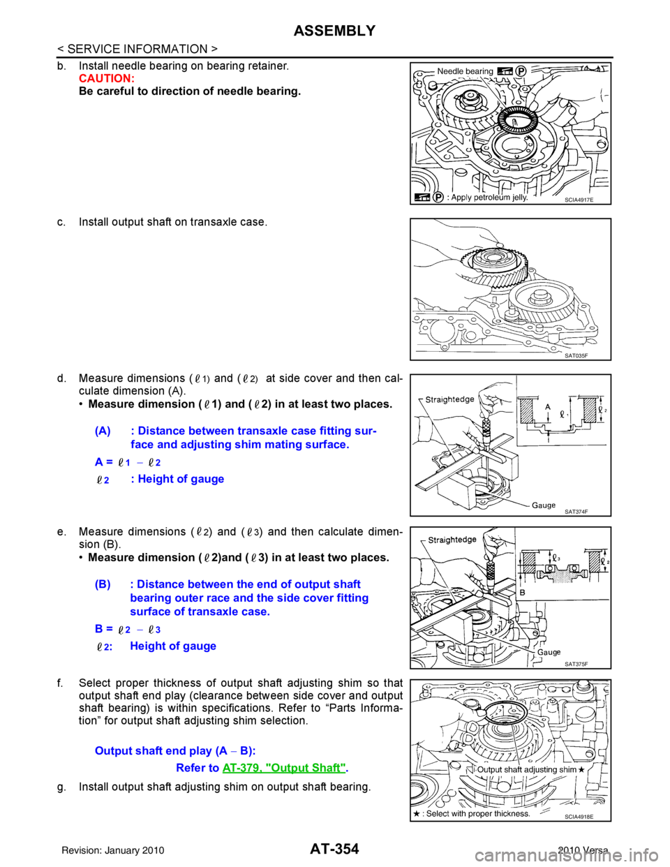
b. Install needle bearing on bearing retainer.CAUTION:
Be careful to direction of needle bearing.
c. Install output shaft on transaxle case.
d. Measure dimensions (
1) and (2) at side cover and then cal-
culate dimension (A).
• Measure dimension ( 1) and ( 2) in at least two places.
e. Measure dimensions (
2) and (3) and then calculate dimen-
sion (B).
• Measure dimension ( 2)and ( 3) in at least two places.
f. Select proper thickness of output shaft adjusting shim so that output shaft end play (clearance between side cover and output
shaft bearing) is within specifications. Refer to “Parts Informa-
tion” for output shaft adjusting shim selection.
g. Install output shaft adjusting shim on output shaft bearing.
SCIA4917E
SAT035F
(A) : Distance between transaxle case fitting sur- face and adjusting shim mating surface.
A =
1 − 2
2
: Height of gauge
SAT374F
(B) : Distance between the end of output shaft bearing outer race and the side cover fitting
surface of transaxle case.
B =
2 − 3
2
: Height of gauge
SAT375F
Output shaft end play (A
− B):
Refer to AT-379, "
Output Shaft".
SCIA4918E
Revision: January 20102010 Versa
Page 377 of 3745
AT-360
< SERVICE INFORMATION >
ASSEMBLY
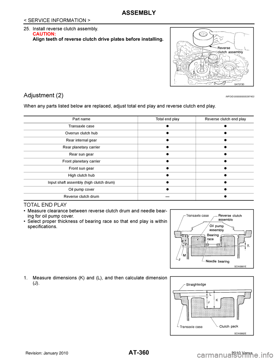
25. Install reverse clutch assembly.CAUTION:
Align teeth of reverse clutch dr ive plates before installing.
Adjustment (2)INFOID:0000000005397453
When any parts listed below are replaced, adjust total end play and reverse clutch end play.
TOTAL END PLAY
• Measure clearance between reverse clutch drum and needle bear-
ing for oil pump cover.
• Select proper thickness of bearing race so that end play is within specifications.
1. Measure dimensions (K) and (L ), and then calculate dimension
(J).
SAT373D
Part name Total end playReverse clutch end play
Transaxle case �z�z
Overrun clutch hub �z�z
Rear internal gear �z�z
Rear planetary carrier �z�z
Rear sun gear �z�z
Front planetary carrier �z�z
Front sun gear �z�z
High clutch hub �z�z
Input shaft assembly (high clutch drum) �z�z
Oil pump cover �z�z
Reverse clutch drum —�z
SCIA3661E
SCIA3662E
Revision: January 20102010 Versa
Page 379 of 3745
AT-362
< SERVICE INFORMATION >
ASSEMBLY
• Select proper thickness of bearing race so that total end play is within specifications. Refer to “PartsInformation” for bearing race selection.
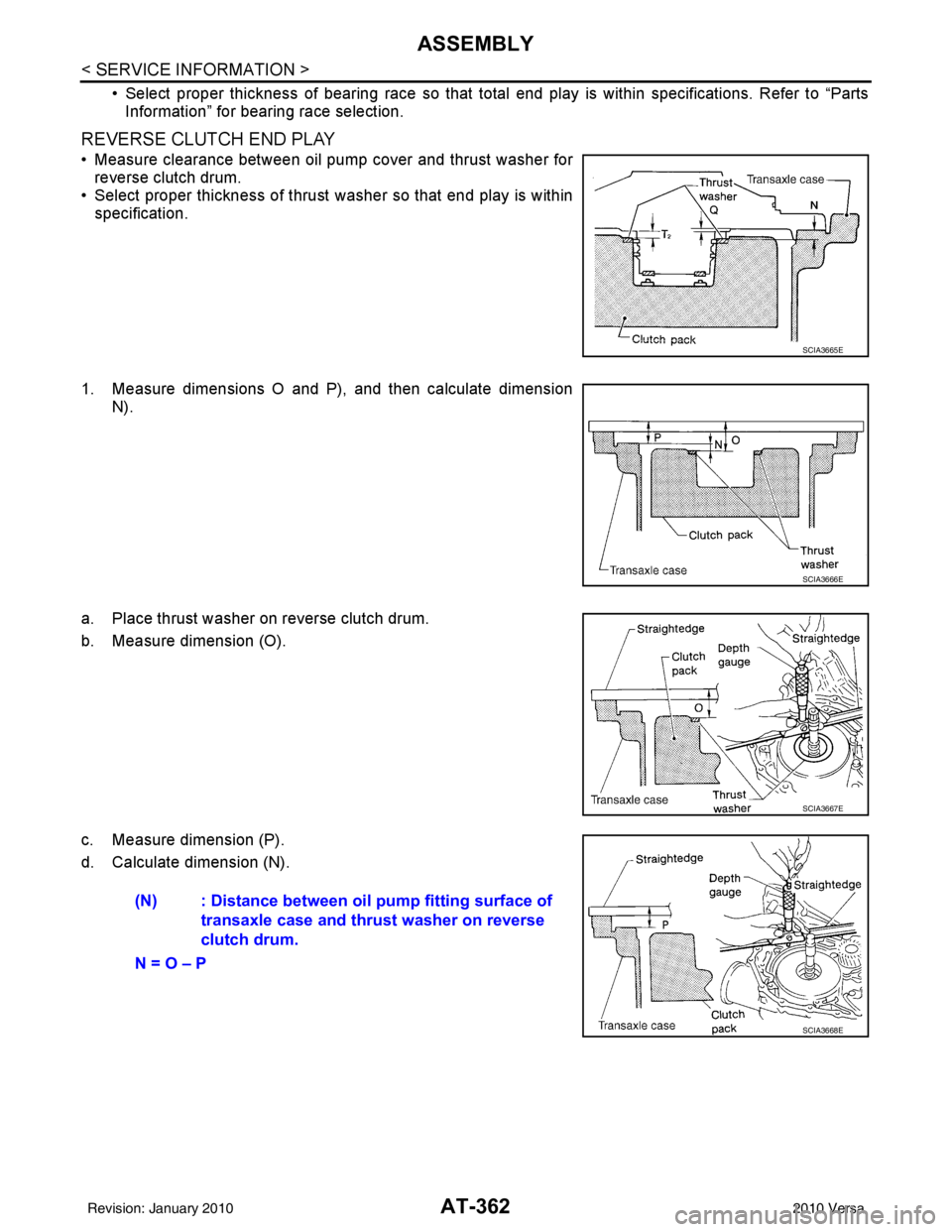
REVERSE CLUTCH END PLAY
• Measure clearance between oil pump cover and thrust washer forreverse clutch drum.
• Select proper thickness of thrust washer so that end play is within
specification.
1. Measure dimensions O and P), and then calculate dimension N).
a. Place thrust washer on reverse clutch drum.
b. Measure dimension (O).
c. Measure dimension (P).
d. Calculate dimension (N).
SCIA3665E
SCIA3666E
SCIA3667E
(N) : Distance between oi l pump fitting surface of
transaxle case and thrust washer on reverse
clutch drum.
N = O – P
SCIA3668E
Revision: January 20102010 Versa