2010 NISSAN TIIDA specifications
[x] Cancel search: specificationsPage 880 of 3745
BR-32
< SERVICE INFORMATION >
FRONT DISC BRAKE
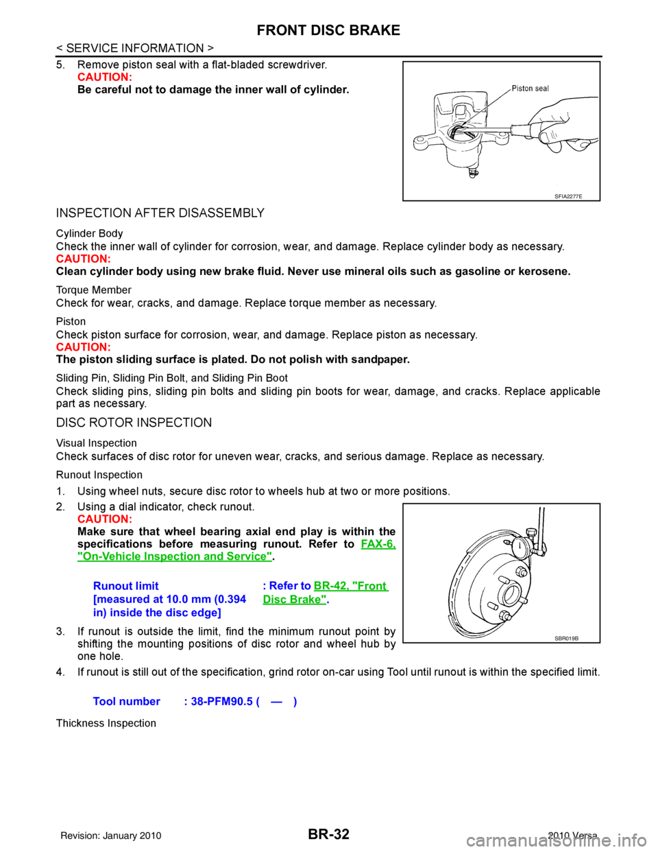
5. Remove piston seal with a flat-bladed screwdriver.CAUTION:
Be careful not to damage the inner wall of cylinder.
INSPECTION AFTER DISASSEMBLY
Cylinder Body
Check the inner wall of cylinder for corrosion, w ear, and damage. Replace cylinder body as necessary.
CAUTION:
Clean cylinder body using new brake fluid. Never use mineral oils such as gasoline or kerosene.
Torque Member
Check for wear, cracks, and damage. R eplace torque member as necessary.
Piston
Check piston surface for corrosion, wear, and damage. Replace piston as necessary.
CAUTION:
The piston sliding surface is plated. Do not polish with sandpaper.
Sliding Pin, Sliding Pin Bolt, and Sliding Pin Boot
Check sliding pins, sliding pin bolts and sliding pin boots for wear, damage, and cracks. Replace applicable
part as necessary.
DISC ROTOR INSPECTION
Visual Inspection
Check surfaces of disc rotor for uneven wear, cr acks, and serious damage. Replace as necessary.
Runout Inspection
1. Using wheel nuts, secure disc rotor to wheels hub at two or more positions.
2. Using a dial indicator, check runout.
CAUTION:
Make sure that wheel bearing axial end play is within the
specifications before measuring runout. Refer to FA X - 6 ,
"On-Vehicle Inspection and Service".
3. If runout is outside the limit, find the minimum runout point by shifting the mounting positions of disc rotor and wheel hub by
one hole.
4. If runout is still out of the specification, grind rotor on-car using Tool until runout is within the specified limit.
Thickness Inspection
SFIA2277E
Runout limit
[measured at 10.0 mm (0.394
in) inside the disc edge] : Refer to BR-42, "Front
Disc Brake".
Tool number : 38-PFM90.5 ( — )
SBR019B
Revision: January 20102010 Versa
Page 881 of 3745
FRONT DISC BRAKEBR-33
< SERVICE INFORMATION >
C
DE
G H
I
J
K L
M A
B
BR
N
O P
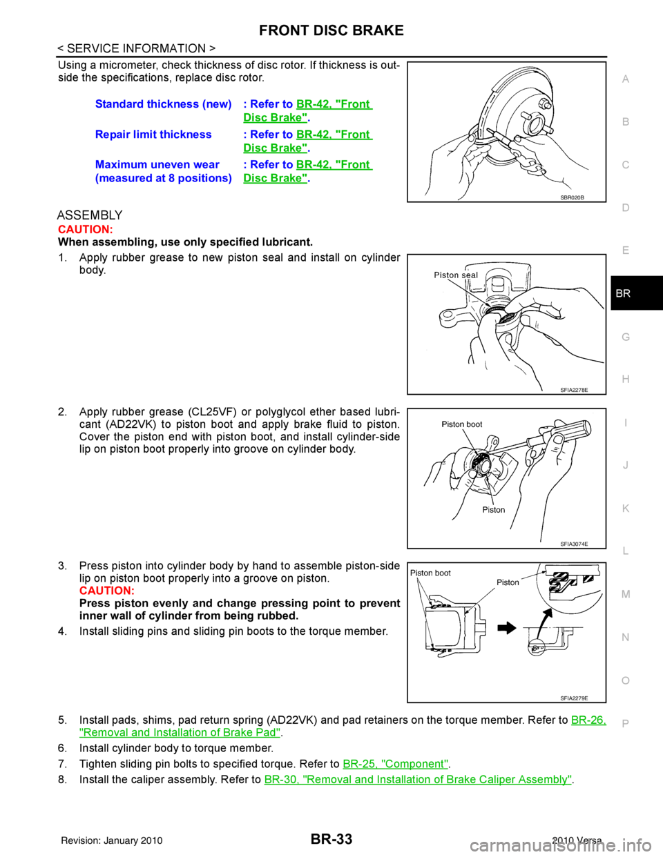
Using a micrometer, check thickness of disc rotor. If thickness is out-
side the specifications, replace disc rotor.
ASSEMBLY
CAUTION:
When assembling, use only specified lubricant.
1. Apply rubber grease to new piston seal and install on cylinder body.
2. Apply rubber grease (CL25VF) or polyglycol ether based lubri- cant (AD22VK) to piston boot and apply brake fluid to piston.
Cover the piston end with piston boot, and install cylinder-side
lip on piston boot properly into groove on cylinder body.
3. Press piston into cylinder body by hand to assemble piston-side lip on piston boot properly into a groove on piston.
CAUTION:
Press piston evenly and change pressing point to prevent
inner wall of cylinder from being rubbed.
4. Install sliding pins and sliding pin boots to the torque member.
5. Install pads, shims, pad return spring (AD22VK) and pad retainers on the torque member. Refer to BR-26,
"Removal and Installation of Brake Pad".
6. Install cylinder body to torque member.
7. Tighten sliding pin bolts to specified torque. Refer to BR-25, "
Component".
8. Install the caliper assembly. Refer to BR-30, "
Removal and Installation of Brake Caliper Assembly".
Standard thickness (new) : Refer to
BR-42, "
Front
Disc Brake".
Repair limit thickness : Refer to BR-42, "
Front
Disc Brake".
Maximum uneven wear
(measured at 8 positions) : Refer to
BR-42, "
Front
Disc Brake".
SBR020B
SFIA2278E
SFIA3074E
SFIA2279E
Revision: January 20102010 Versa
Page 888 of 3745

BR-40
< SERVICE INFORMATION >
SERVICE DATA AND SPECIFICATIONS (SDS)
SERVICE DATA AND SPECIFICATIONS (SDS)
General SpecificationINFOID:0000000005397007
HR16DE
MR18DE
TypeWith ABS only or VDC/TCS/ABSWithout ABS
Front brake Brake model AD22VK
Cylinder bore diameter 53.97 mm (2.125 in)
Pad
Length × width × thickness 115.0 mm ×
41.0 mm × 9.0 mm
(4.528 in × 1.614 in × 0.354 in)
Rotor outer diameter × thickness 260 mm × 22.0 mm (10.24 in × 0.866 in)
Rear brake Brake model LT20
Cylinder bore diameter 15.87 mm (0.625 in)17.46 mm (0.687 in)
Drum inner diameter 203 mm (7.992 in)
Master cylinder Cylinder bore diameter 22.22 mm (0.875 in)
Brake booster Booster model C255
Diaphragm diameter 255 mm (10.04 in)
Recommended brake fluid DOT 3
Front brake Brake modelCLZ25VF
Cylinder bore diameter 57.2 mm (2.252 in)
Pad
Length × width × thickness 125.6 mm
× 48.0 mm × 9.5 mm
(4.945 in × 1.890 in × 0.374 in)
Rotor outer diameter × thickness 280 mm × 24.0 mm (11.02 in × 0.945 in)
Rear brake Brake model LT23
Cylinder bore diameter 19.06 mm (0.750 in)
Drum inner diameter 228.6 mm (9.000 in)
Master cylinder Cylinder bore diameter 23.81 ± 0.015 mm (0.937 ± 0.001 in)
Brake booster Booster model C255
Diaphragm diameter 255 mm (10.04 in)
Recommended brake fluid DOT 3
Revision: January 20102010 Versa
Page 889 of 3745
SERVICE DATA AND SPECIFICATIONS (SDS)BR-41
< SERVICE INFORMATION >
C
DE
G H
I
J
K L
M A
B
BR
N
O P
Brake PedalINFOID:0000000005397008
Unit: mm (in)
Check ValveINFOID:0000000005397009
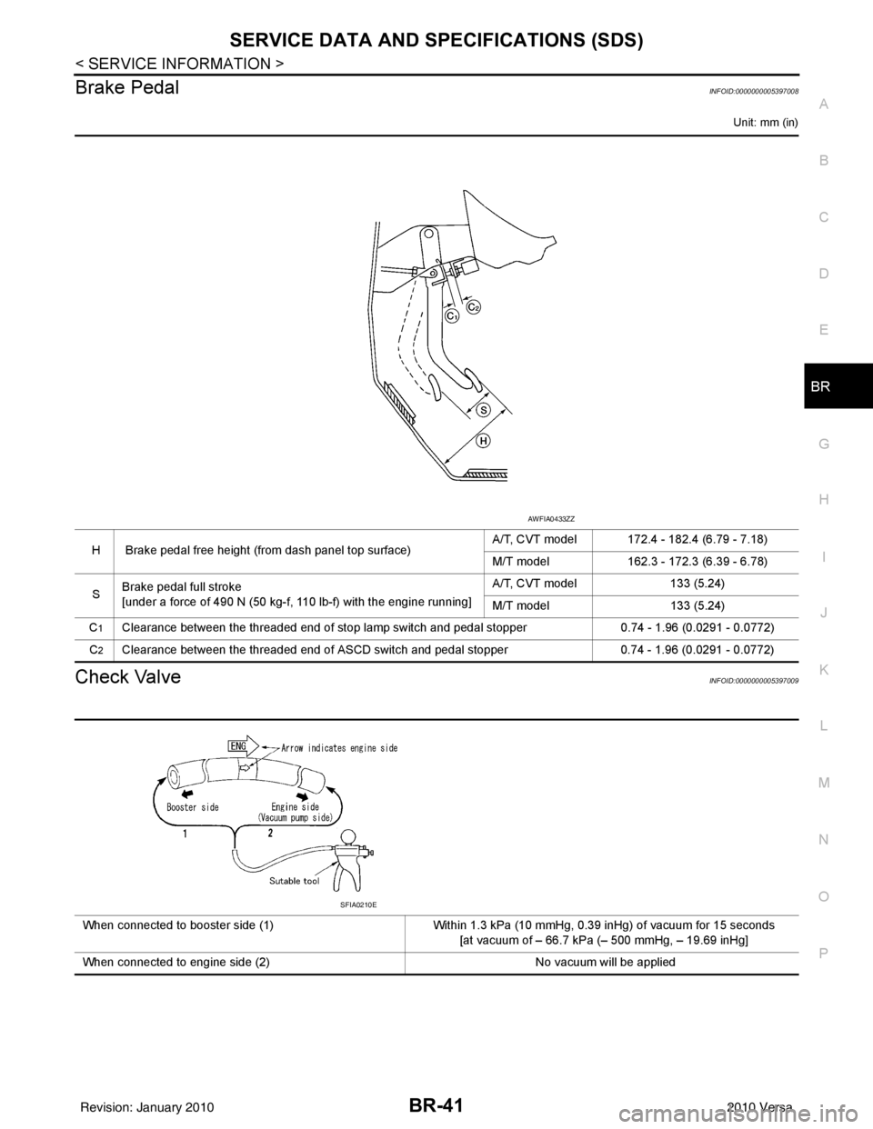
H Brake pedal free height (from dash panel top surface) A/T, CVT model 172.4 - 182.4 (6.79 - 7.18)
M/T model
162.3 - 172.3 (6.39 - 6.78)
S Brake pedal full stroke
[under a force of 490 N (50 kg-f, 110 lb-f) with the engine running] A/T, CVT model
133 (5.24)
M/T model 133 (5.24)
C
1Clearance between the threaded end of stop lamp switch and pedal stopper 0.74 - 1.96 (0.0291 - 0.0772)
C
2Clearance between the threaded end of ASCD switch and pedal stopper 0.74 - 1.96 (0.0291 - 0.0772)
AWFIA0433ZZ
When connected to booster side (1)Within 1.3 kPa (10 mmHg, 0.39 inHg) of vacuum for 15 seconds
[at vacuum of – 66.7 kPa (– 500 mmHg, – 19.69 inHg]
When connected to engine side (2) No vacuum will be applied
SFIA0210E
Revision: January 20102010 Versa
Page 890 of 3745
BR-42
< SERVICE INFORMATION >
SERVICE DATA AND SPECIFICATIONS (SDS)
Brake Booster
INFOID:0000000005397010
Front Disc BrakeINFOID:0000000005397011
Unit: mm (in)
Unit: mm (in)
Rear Drum BrakeINFOID:0000000005397012
Unit: mm (in)
Unit: mm (in)
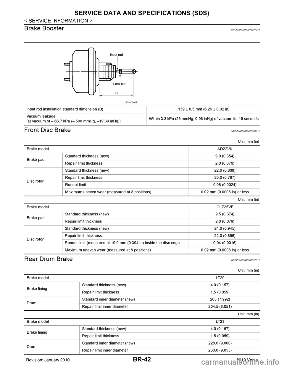
Input rod installation standard dimension (B) 159 ± 0.5 mm (6.26 ± 0.02 in)
Vacuum leakage
[at vacuum of – 66.7 kPa (– 500 mmHg, –19.69 inHg)] Within 3.3 kPa (25 mmHg, 0.98 inHg) of vacuum for 15 seconds
SGIA0060E
Brake model
AD22VK
Brake pad Standard thickness (new)
9.0 (0.354)
Repair limit thickness 2.0 (0.079)
Disc rotor Standard thickness (new)
22.0 (0.866)
Repair limit thickness 20.0 (0.787)
Runout limit 0.06 (0.0024)
Maximum uneven wear (measured at 8 positions) 0.02 mm (0.0008 in) or less
Brake model CLZ25VF
Brake pad Standard thickness (new)
9.5 (0.374)
Repair limit thickness 2.0 (0.079)
Disc rotor Standard thickness (new)
24.0 (0.945)
Repair limit thickness 22.0 (0.866)
Runout limit (measured at 10.0 mm (0.394 in) inside the disc edge 0.04 (0.0016)
Maximum uneven wear (measured at 8 positions) 0.02 mm (0.0008 in) or less
Brake model LT 2 0
Brake lining Standard thickness
(new) 4.0 (0.157)
Repair limit thickness 1.5 (0.059)
Drum Standard inner diameter (new)
203 (7.992)
Repair limit inner diameter 204.5 (8.051)
Brake model LT 2 3
Brake lining Standard thickness (new)
4.0 (0.157)
Repair limit thickness 1.5 (0.059)
Drum Standard inner diameter (new)
228.6 (9.000)
Repair limit inner diameter 230.0 (9.055)
Revision: January 20102010 Versa
Page 916 of 3745
![NISSAN TIIDA 2010 Service Repair Manual BRC-26
< SERVICE INFORMATION >[ABS]
TROUBLE DIAGNOSIS FOR
SELF-DIAGNOSTIC ITEMS
TROUBLE DIAGNOSIS FOR SELF-DIAGNOSTIC ITEMS
Wheel Sensor SystemINFOID:0000000005397040
INSPECTION PROCEDURE
1.CONNECTOR](/manual-img/5/57397/w960_57397-915.png "NISSAN TIIDA 2010 Service Repair Manual BRC-26
< SERVICE INFORMATION >[ABS]
TROUBLE DIAGNOSIS FOR
SELF-DIAGNOSTIC ITEMS
TROUBLE DIAGNOSIS FOR SELF-DIAGNOSTIC ITEMS
Wheel Sensor SystemINFOID:0000000005397040
INSPECTION PROCEDURE
1.CONNECTOR")
BRC-26
< SERVICE INFORMATION >[ABS]
TROUBLE DIAGNOSIS FOR
SELF-DIAGNOSTIC ITEMS
TROUBLE DIAGNOSIS FOR SELF-DIAGNOSTIC ITEMS
Wheel Sensor SystemINFOID:0000000005397040
INSPECTION PROCEDURE
1.CONNECTOR INSPECTION
Disconnect the ABS actuator and electric unit (control unit) connector E33 and wheel sensor of malfunctioning
code.
Check the terminals for deformation, disconnection, looseness or damage.
OK or NG
OK >> GO TO 2.
NG >> Repair or replace as necessary.
2.CHECK WHEEL SENSOR OUTPUT SIGNAL
1. Connect ABS active wheel sensor tester (J-45741) to wheel sensor using appropriate adapter.
2. Turn on the ABS active wheel sensor tester power switch. NOTE:
The green POWER indicator should illuminate. If the POWER indicator does not illuminate, replace the
battery in the ABS active wheel sensor tester before proceeding.
3. Spin the wheel of the vehicle by hand and observe the red SENSOR indicator on the ABS active wheel
sensor tester. The red SENSOR indicator should flash on and off to indicate an output signal.
NOTE:
If the red SENSOR indicator illuminates but does not flash, reverse the polarity of the tester leads and
retest.
Does the ABS active wheel sensor tester detect a signal?
YES >> GO TO 3.
NO >> Replace the wheel sensor. Refer to BRC-34, "
Removal and Installation".
3.CHECK TIRES
Check for inflation pressure, wear and size of each tire. Refer to WT-28
.
Are tire pressure and size correct and is tire wear within specifications?
YES >> GO TO 4.
NO >> Adjust tire pressure or replace tire(s).
4.CHECK WHEEL BEARINGS
Check wheel bearing axial end play. Refer to FAX-6, "
On-Vehicle Inspection and Service" or RAX-6, "On-Vehi-
cle Inspection and Service".
OK or NG
OK >> GO TO 5.
NG >> Repair or replace as necessary. Refer to FA X - 6 , "
Removal and Installation" or RAX-6, "Removal
and Installation".
5.CHECK WIRING HARNESS FOR SHORT CIRCUIT
1. Turn ignition switch OFF.
2. Disconnect ABS actuator and elec tric unit (control unit) connec-
tor and wheel sensor connector of malfunction code No.
3. Check continuity between wheel sensor harness connector ter- minals and ground.
OK or NG
OK >> GO TO 6.
NG >> Repair the circuit.
6.CHECK WIRING HARNESS FOR OPEN CIRCUIT Continuity should not exist.
WFIA0498E
Revision: January 20102010 Versa
Page 957 of 3745
![NISSAN TIIDA 2010 Service Repair Manual TROUBLE DIAGNOSIS FOR SELF-DIAGNOSTIC ITEMS
BRC-67
< SERVICE INFORMATION > [VDC/TCS/ABS]
C
D
E
G H
I
J
K L
M A
B
BRC
N
O P
TROUBLE DIAGNOSIS FOR SELF-DIAGNOSTIC ITEMS
Wheel Sensor System InspectionIN](/manual-img/5/57397/w960_57397-956.png "NISSAN TIIDA 2010 Service Repair Manual TROUBLE DIAGNOSIS FOR SELF-DIAGNOSTIC ITEMS
BRC-67
< SERVICE INFORMATION > [VDC/TCS/ABS]
C
D
E
G H
I
J
K L
M A
B
BRC
N
O P
TROUBLE DIAGNOSIS FOR SELF-DIAGNOSTIC ITEMS
Wheel Sensor System InspectionIN")
TROUBLE DIAGNOSIS FOR SELF-DIAGNOSTIC ITEMS
BRC-67
< SERVICE INFORMATION > [VDC/TCS/ABS]
C
D
E
G H
I
J
K L
M A
B
BRC
N
O P
TROUBLE DIAGNOSIS FOR SELF-DIAGNOSTIC ITEMS
Wheel Sensor System InspectionINFOID:0000000005612159
INSPECTION PROCEDURE
1.CONNECTOR INSPECTION
Disconnect the ABS actuator and electric unit (control unit) connector E33 and wheel sensor of malfunctioning
code.
Check the terminals for deformation, disconnection, looseness or damage.
OK or NG
OK >> GO TO 2.
NG >> Repair or replace as necessary.
2.CHECK WHEEL SENSOR OUTPUT SIGNAL
1. Connect ABS active wheel sensor tester (J- 45741) to wheel sensor using appropriate adapter.
2. Turn on the ABS active wheel sensor tester power switch.
NOTE:
The green POWER indicator should illuminate. If the POWER indicator does not illuminate, replace the
battery in the ABS active wheel sensor tester before proceeding.
3. Spin the wheel of the vehicle by hand and observe the red SENSOR indicator on the ABS active wheel
sensor tester. The red SENSOR indicator should flash on and off to indicate an output signal.
NOTE:
If the red SENSOR indicator illuminates but does not flash, reverse the polarity of the tester leads and
retest.
Does the ABS active wheel s ensor tester detect a signal?
YES >> GO TO 3.
NO >> Replace the wheel sensor. Refer to BRC-86, "
Removal and Installation".
3.CHECK TIRES
Check for inflation pressure, wear and size of each tire. Refer to WT-28, "
Tire".
Are tire pressure and size correct and is tire wear within specifications?
YES >> GO TO 4.
NO >> Adjust tire pressure or replace tire(s).
4.CHECK WHEEL BEARINGS
Check wheel bearing axial end play. Refer to FA X - 6 , "
On-Vehicle Inspection and Service" or RAX-6, "On-Vehi-
cle Inspection and Service".
OK or NG
OK >> GO TO 5.
NG >> Repair or replace as necessary. Refer to FAX-6, "
Removal and Installation" (front) or RAX-6,
"Removal and Installation" (rear).
5.CHECK WIRING HARNESS FOR SHORT CIRCUIT
1. Turn the ignition switch OFF.
2. Disconnect ABS actuator and electric unit (control unit) connec- tor and wheel sensor connector of malfunction code No.
3. Check continuity between wheel sensor harness connector ter- minals and ground.
OK or NG
OK >> GO TO 6.
NG >> Repair the circuit.
6.CHECK WIRING HARNESS FOR OPEN CIRCUIT Continuity should not exist.
WFIA0498E
Revision: January 20102010 Versa
Page 983 of 3745

CO-1
ENGINE
C
DE
F
G H
I
J
K L
M
SECTION CO
A
CO
N
O P
CONTENTS
ENGINE COOLING SYSTEM
HR16DE
PRECAUTION ....... ........................................
3
PRECAUTIONS .............................................. .....3
Precaution for Supplemental Restraint System
(SRS) "AIR BAG" and "SEAT BELT PRE-TEN-
SIONER" ............................................................. ......
3
Precaution Necessary for Steering Wheel Rota-
tion After Battery Disconnect ............................... ......
3
Precaution for Liquid Gasket .....................................4
PREPARATION ............................................6
PREPARATION .............................................. .....6
Special Service Tool ........................................... ......6
Commercial Service Tool ..........................................6
SYMPTOM DIAGNOSIS ...............................8
OVERHEATING CAUSE ANALYSIS ............. .....8
Troubleshooting Chart ...............................................8
FUNCTION DIAGNOSIS .. ............................10
DESCRIPTION ............................................... ....10
Engine Cooling System ....................................... ....10
Engine Cooling System Schematic .........................11
ON-VEHICLE MAINTENANCE ....................12
ENGINE COOLANT ....................................... ....12
Inspection ............................................................ ....12
Changing Engine Coolant .......................................12
RADIATOR .........................................................15
Checking Radiator Cap ....................................... ....15
Checking Radiator ...................................................15
ON-VEHICLE REPAIR .................................17
RADIATOR ..................................................... ....17
Component .......................................................... ....17
Removal and Installation ..................................... ....17
COOLING FAN ..................................................19
Component (Models with A/C) .................................19
Component (Models without A/C) ............................19
Removal and Installation .........................................20
Disassembly and Assembly .....................................20
WATER PUMP ..................................................21
Exploded View .........................................................21
Removal and Installation .........................................21
Inspection ................................................................22
THERMOSTAT ..................................................23
Exploded View .........................................................23
Removal and Installation .........................................23
Inspection ................................................................24
WATER OUTLET ..............................................25
Exploded View .........................................................25
Removal and Installation .........................................25
Inspection ................................................................26
SERVICE DATA AND SPECIFICATIONS
(SDS) ............... .......................................... ...
27
SERVICE DATA AND SPECIFICATIONS
(SDS) .................................................................
27
Periodical Maintenance Specification .................. ....27
Radiator ...................................................................27
Thermostat ..............................................................27
MR18DE
SERVICE INFORMATION .. .........................
28
PRECAUTIONS .................................................28
Precaution for Supplemental Restraint System
(SRS) "AIR BAG" and "SEAT BELT PRE-TEN-
SIONER" ............................................................. ....
28
Precaution Necessary for Steering Wheel Rota-
tion After Battery Disconnect ...................................
28
Precaution for Liquid Gasket ...................................29
Revision: January 20102010 Versa