2010 NISSAN TIIDA oil pressure
[x] Cancel search: oil pressurePage 1224 of 3745

DI-14
< SERVICE INFORMATION >
COMBINATION METERS
NOTE:
Some items are not available due to vehicle specification.
*: The monitor will indicate “OFF” even though the brake warning lamp is on if either of the following conditions exist.
• The parking brake is engaged
• The brake fluid level is low
Trouble DiagnosisINFOID:0000000005395016
HOW TO PERFORM TROUBLE DIAGNOSIS
1. Confirm the symptom or customer complaint.
2. Perform preliminary check. Refer to "PRELIMINARY CHECK" .
3. According to the symptom chart, repair or replace the cause of the malfunction. Refer to DI-15, "
Symptom
Chart" .
4. Does the meter operate normally? If so, GO TO 5. If not, GO TO 2.
5. Inspection End.
PRELIMINARY CHECK
1.CHECK SELF-DIAGNOSIS OPERAT ION OF COMBINATION METER
Perform self-diagnosis of combination meter. Refer to DI-11, "
Self-Diagnosis Mode of Combination Meter" .
Does self
-diagnosis mode operate?
TURN IND [ON/OFF] X Indicates [ON/OFF] condition of turn indicator.
OIL W/L [ON/OFF] X Indicates [ON/OFF] condition of oil pressure warning lamp.
VDC/TCS IND [ON/OFF] X Indicates [ON/OFF] condition of VDC OFF indicator lamp.
ABS W/L [ON/OFF] X Indicates [ON/OFF] condition of ABS warning lamp.
SLIP IND [ON/OFF] X Indicates [ON/OFF] condition of SLIP indicator lamp.
BRAKE W/L [ON/OFF] X Indicates [ON/OFF] condition of brake warning lamp.*
KEY G W/L [ON/OFF] X Indicates [ON/OFF] condition of KEY warning lamp (green).
KEY R W/L [ON/OFF] X Indicates [ON/OFF] condition of KEY warning lamp (red).
KEY KNOB W/L [ON/OFF] X Indicates [ON/OFF] condition of LOCK warning lamp.
PNP P SW [ON/OFF] XX Indicates [ON/OFF] condition of inhibitor P switch.
PNP N SW [ON/OFF] XX Indicates [ON/OFF] condition of inhibitor N switch.
O/D OFF SW [ON/OFF] X Indicates [ON/OFF] condition of O/D OFF switch.
BRAKE SW [ON/OFF] X Indicates [ON/OFF] condition of parking brake switch.
P RANGE IND [ON/OFF] XXIndicates [ON/OFF] condition of A/T or CVT shift P range indi-
cator.
R RANGE IND [ON/OFF] XXIndicates [ON/OFF] condition of A/T or CVT shift R range indi-
cator.
N RANGE IND [ON/OFF] XXIndicates [ON/OFF] condition of A/T or CVT shift N range indi-
cator.
D RANGE IND [ON/OFF] XXIndicates [ON/OFF] condition of A/T or CVT shift D range indi-
cator.
2 RANGE IND [ON/OFF] XX Indicates [ON/OFF] condition of A/T shift 2 range indicator.
L RANGE IND [ON/OFF] XX Indicates [ON/OFF] condition of CVT shift L range indicator.
1 RANGE IND [ON/OFF] XX Indicates [ON/OFF] condition of A/T shift 1 range indicator.
CRUISE IND [ON/OFF] X Indicates [ON/OFF] condition of CRUISE indicator.
SET IND [ON/OFF] X Indicates [ON/OFF] condition of SET indicator.
O/D OFF W/L [ON/OFF] X Indicates [ON/OFF] condition of O/D OFF indicator lamp.
EPS W/L [ON/OFF] X Indicates [ON/OFF] condition of EPS warning lamp.
Display item [Unit]
MAIN
SIGNALS SELECTION
FROM MENU Contents
Revision: January 20102010 Versa
Page 1240 of 3745

DI-30
< SERVICE INFORMATION >
WARNING LAMPS
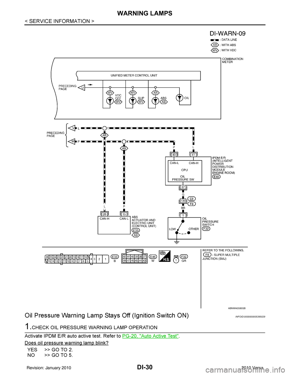
Oil Pressure Warning Lamp Stays Off (Ignition Switch ON)
INFOID:0000000005395029
1.CHECK OIL PRESSURE WARNING LAMP OPERATION
Activate IPDM E/R auto active test. Refer to PG-20, "
Auto Active Test".
Does oil pressure warning lamp blink?
YES >> GO TO 2.
NO >> GO TO 5.
ABNWA0595GB
Revision: January 20102010 Versa
Page 1241 of 3745

WARNING LAMPSDI-31
< SERVICE INFORMATION >
C
DE
F
G H
I
J
L
M A
B
DI
N
O P
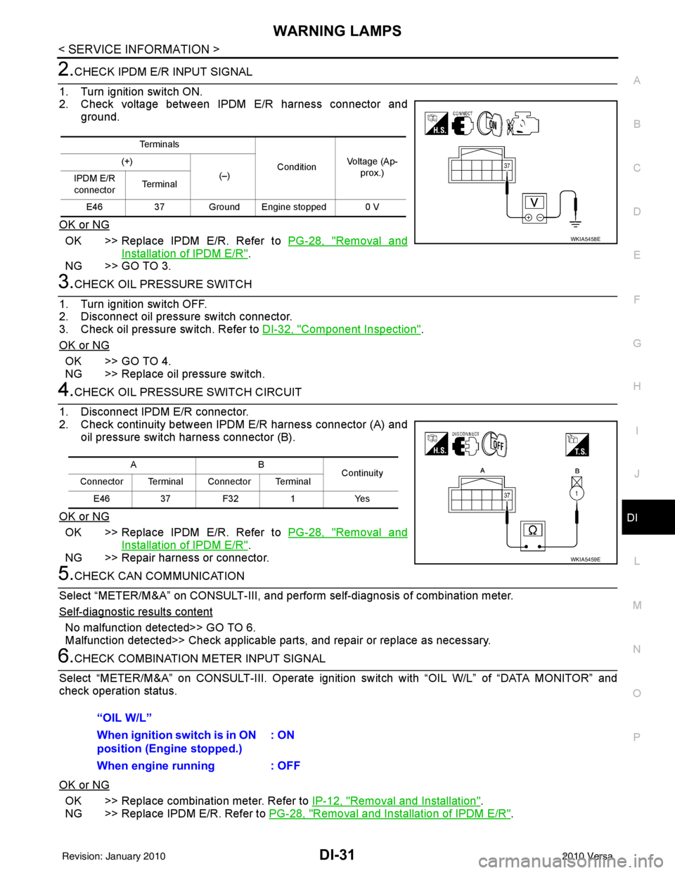
2.CHECK IPDM E/R INPUT SIGNAL
1. Turn ignition switch ON.
2. Check voltage between IPDM E/R harness connector and ground.
OK or NG
OK >> Replace IPDM E/R. Refer to PG-28, "Removal and
Installation of IPDM E/R".
NG >> GO TO 3.
3.CHECK OIL PRESSURE SWITCH
1. Turn ignition switch OFF.
2. Disconnect oil pressure switch connector.
3. Check oil pressure switch. Refer to DI-32, "
Component Inspection".
OK or NG
OK >> GO TO 4.
NG >> Replace oil pressure switch.
4.CHECK OIL PRESSURE SWITCH CIRCUIT
1. Disconnect IPDM E/R connector.
2. Check continuity between IPDM E/R harness connector (A) and oil pressure switch harness connector (B).
OK or NG
OK >> Replace IPDM E/R. Refer to PG-28, "Removal and
Installation of IPDM E/R".
NG >> Repair harness or connector.
5.CHECK CAN COMMUNICATION
Select “METER/M&A” on CONSULT-III, and per form self-diagnosis of combination meter.
Self
-diagnostic results content
No malfunction detected>> GO TO 6.
Malfunction detected>> Check applicable parts, and repair or replace as necessary.
6.CHECK COMBINATION METER INPUT SIGNAL
Select “METER/M&A” on CONS ULT-III. Operate ignition switch with “OIL W/L” of “DATA MONITOR” and
check operation status.
OK or NG
OK >> Replace combination meter. Refer to IP-12, "Removal and Installation".
NG >> Replace IPDM E/R. Refer to PG-28, "
Removal and Installation of IPDM E/R".
Te r m i n a l s
ConditionVoltage (Ap-
prox.)
(+)
(–)
IPDM E/R
connector Te r m i n a l
E46 37 Ground Engine stopped 0 V
WKIA5458E
AB
Continuity
Connector Terminal Connector Terminal
E46 37 F32 1 Yes
WKIA5459E
“OIL W/L”
When ignition switch is in ON
position (Engine stopped.) : ON
When engine running : OFF
Revision: January 20102010 Versa
Page 1242 of 3745

DI-32
< SERVICE INFORMATION >
WARNING LAMPS
Oil Pressure Warning Lamp Does Not Turn Off (Oil Pressure Is Normal)
INFOID:0000000005395030
NOTE:
For oil pressure inspection, refer to LU-17, "
Inspection".
1.CHECK OIL PRESSURE WARNING LAMP OPERATION
Activate IPDM E/R auto active test. Refer to PG-20, "
Auto Active Test".
Does oil pressure warning lamp blink?
YES >> GO TO 2.
NO >> GO TO 5.
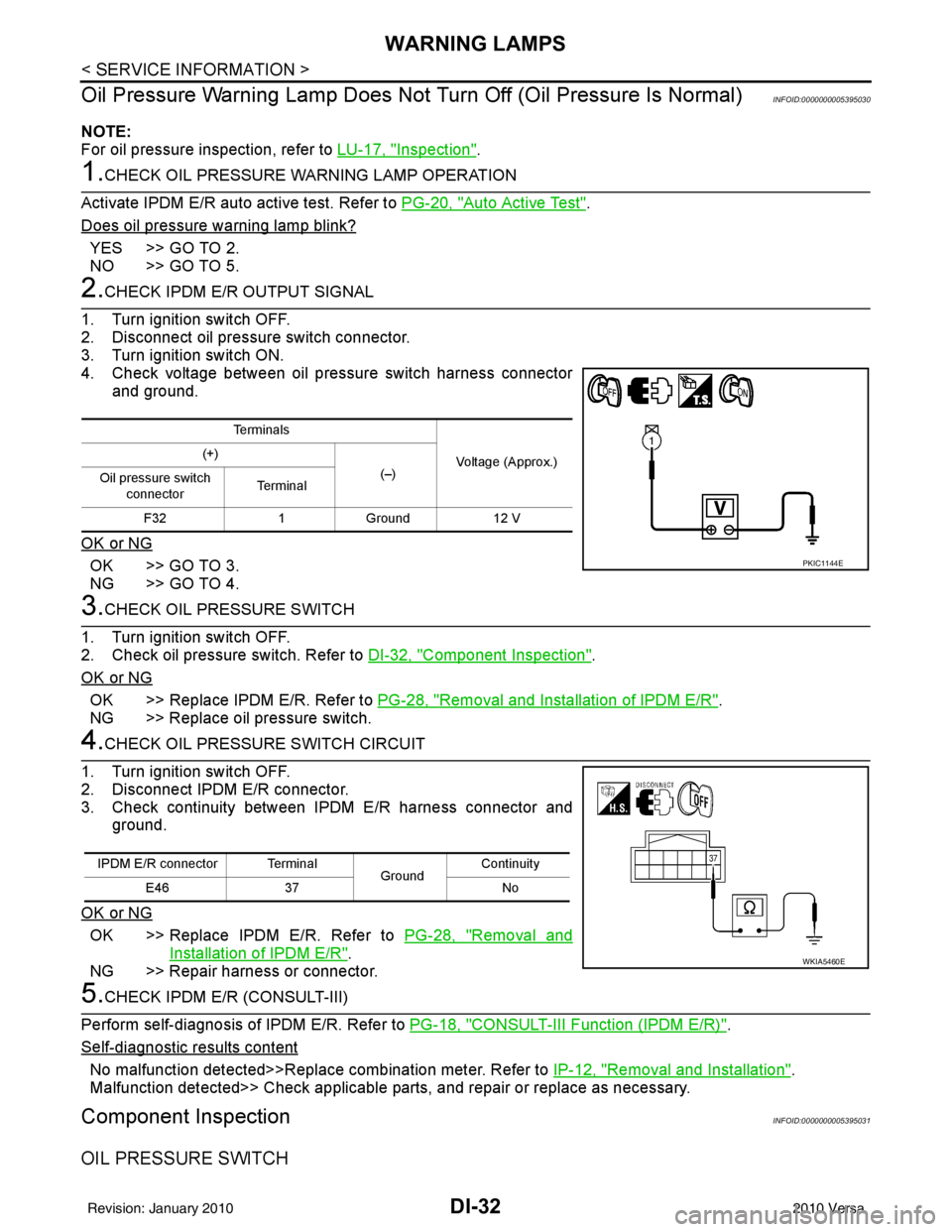
2.CHECK IPDM E/R OUTPUT SIGNAL
1. Turn ignition switch OFF.
2. Disconnect oil pressure switch connector.
3. Turn ignition switch ON.
4. Check voltage between oil pressure switch harness connector and ground.
OK or NG
OK >> GO TO 3.
NG >> GO TO 4.
3.CHECK OIL PRESSURE SWITCH
1. Turn ignition switch OFF.
2. Check oil pressure switch. Refer to DI-32, "
Component Inspection".
OK or NG
OK >> Replace IPDM E/R. Refer to PG-28, "Removal and Installation of IPDM E/R".
NG >> Replace oil pressure switch.
4.CHECK OIL PRESSURE SWITCH CIRCUIT
1. Turn ignition switch OFF.
2. Disconnect IPDM E/R connector.
3. Check continuity between IPDM E/R harness connector and ground.
OK or NG
OK >> Replace IPDM E/R. Refer to PG-28, "Removal and
Installation of IPDM E/R".
NG >> Repair harness or connector.
5.CHECK IPDM E/R (CONSULT-III)
Perform self-diagnosis of IPDM E/R. Refer to PG-18, "
CONSULT-III Function (IPDM E/R)".
Self
-diagnostic results content
No malfunction detected>>Replace combination meter. Refer to IP-12, "Removal and Installation".
Malfunction detected>> Check applicable parts, and repair or replace as necessary.
Component InspectionINFOID:0000000005395031
OIL PRESSURE SWITCH
Te r m i n a l s
Voltage (Approx.)
(+)
(–)
Oil pressure switch
connector Te r m i n a l
F32 1Ground 12 V
PKIC1144E
IPDM E/R connector Terminal
GroundContinuity
E46 37 No
WKIA5460E
Revision: January 20102010 Versa
Page 1243 of 3745
![NISSAN TIIDA 2010 Service Repair Manual WARNING LAMPSDI-33
< SERVICE INFORMATION >
C
DE
F
G H
I
J
L
M A
B
DI
N
O P
Check continuity between oil pressure switch and ground.
Condition Oil pressure [kPa (bar, kg/cm2, psi)]Continuity
Engine sto NISSAN TIIDA 2010 Service Repair Manual WARNING LAMPSDI-33
< SERVICE INFORMATION >
C
DE
F
G H
I
J
L
M A
B
DI
N
O P
Check continuity between oil pressure switch and ground.
Condition Oil pressure [kPa (bar, kg/cm2, psi)]Continuity
Engine sto](/manual-img/5/57397/w960_57397-1242.png)
WARNING LAMPSDI-33
< SERVICE INFORMATION >
C
DE
F
G H
I
J
L
M A
B
DI
N
O P
Check continuity between oil pressure switch and ground.
Condition Oil pressure [kPa (bar, kg/cm2, psi)]Continuity
Engine stopped Less than 29 (0.3, 0.3, 4) Yes
Engine running More than 29 (0.3, 0.3, 4) No
ELF0044D
Revision: January 20102010 Versa
Page 1271 of 3745

EC-6
Wiring Diagram ......................................................402
Diagnosis Procedure .............................................402
Component Inspection ...........................................404
Special Repair Requirement ..................................404
P2138 APP SENSOR ..................................... .405
Description ........................................................... ..405
DTC Logic ..............................................................405
Wiring Diagram ......................................................406
Diagnosis Procedure .............................................406
Component Inspection ...........................................409
Special Repair Requirement ..................................409
P2A00 A/F SENSOR 1 ................................... .410
Description ........................................................... ..410
DTC Logic ..............................................................410
Wiring Diagram ......................................................411
Diagnosis Procedure .............................................412
COOLING FAN ................................................415
Description ........................................................... ..415
Component Function Check ..................................415
Wiring Diagram ......................................................416
Diagnosis Procedure .............................................417
Component Inspection ...........................................419
ELECTRICAL LOAD SIGNAL .........................421
Description ........................................................... ..421
Component Function Check ..................................421
Diagnosis Procedure .............................................421
FUEL INJECTOR .............................................423
Description ........................................................... ..423
Component Function Check ..................................423
Wiring Diagram ......................................................424
Diagnosis Procedure .............................................424
Component Inspection ...........................................425
FUEL PUMP .....................................................427
Description ........................................................... ..427
Component Function Check ..................................427
Wiring Diagram ......................................................428
Diagnosis Procedure .............................................428
Component Inspection ...........................................430
IGNITION SIGNAL ...........................................432
Description ........................................................... ..432
Component Function Check ..................................432
Wiring Diagram ......................................................433
Diagnosis Procedure .............................................434
Component Inspection (Ignition Coil with Power
Transistor) .............................................................
437
Component Inspection (Condenser-2) ..................438
MALFUNCTION INDICATOR LAMP ...............439
Description ........................................................... ..439
Component Function Check ..................................439
Wiring Diagram ......................................................440
Diagnosis Procedure .............................................441
ON BOARD REFUELING VAPOR RECOV-
ERY (ORVR) .....................................................
443
Description ........................................................... .443
Component Function Check .................................443
Diagnosis Procedure .............................................443
Component Inspection (Refueling EVAP vapor cut
valve) ................................................................... .
446
Component Inspection (Drain filter) ......................448
POSITIVE CRANKCASE VENTILATION .........449
Description ........................................................... .449
Component Inspection ..........................................449
REFRIGERANT PRESSURE SENSOR ...........450
Description ........................................................... .450
Component Function Check .................................450
Wiring Diagram .....................................................451
Diagnosis Procedure .............................................451
ECU DIAGNOSIS ......................................454
ECM ................................................................ ..454
Reference Value .................................................. .454
Wiring Diagram — ENGINE CONTROL SYSTEM
— ..........................................................................
464
Fail Safe ...............................................................465
DTC Inspection Priority Chart .............................467
DTC Index ............................................................468
How to Set SRT Code .......................................471
How to Erase Permanent DTC .............................473
Test Value and Test Limit .....................................477
SYMPTOM DIAGNOSIS ...........................484
ENGINE CONTROL SYSTEM SYMPTOMS .. ..484
Symptom Table .................................................... .484
NORMAL OPERATING CONDITION ...............488
Description ........................................................... .488
PRECAUTION ...........................................489
PRECAUTIONS .............................................. ..489
Precaution for Supplemental Restraint System
(SRS) "AIR BAG" and "SEAT BELT PRE-TEN-
SIONER" .............................................................. .
489
Precaution Necessary for Steering Wheel Rota-
tion After Battery Disconnect ................................
489
Precaution for Procedure without Cowl Top Cover .490
On Board Diagnosis (OBD) System of Engine and
A/T ........................................................................
490
General Precautions .............................................490
PREPARATION .........................................494
PREPARATION .............................................. ..494
Special Service Tools .......................................... .494
Commercial Service Tools ....................................494
ON-VEHICLE MAINTENANCE .................496
Revision: January 20102010 Versa
Page 1295 of 3745
![NISSAN TIIDA 2010 Service Repair Manual EC-30
< FUNCTION DIAGNOSIS >[HR16DE]
ENGINE CONTROL SYSTEM
System Description
INFOID:0000000005398249
ECM performs various controls such as fuel injection control and ignition timing control.
Componen NISSAN TIIDA 2010 Service Repair Manual EC-30
< FUNCTION DIAGNOSIS >[HR16DE]
ENGINE CONTROL SYSTEM
System Description
INFOID:0000000005398249
ECM performs various controls such as fuel injection control and ignition timing control.
Componen](/manual-img/5/57397/w960_57397-1294.png)
EC-30
< FUNCTION DIAGNOSIS >[HR16DE]
ENGINE CONTROL SYSTEM
System Description
INFOID:0000000005398249
ECM performs various controls such as fuel injection control and ignition timing control.
Component Parts LocationINFOID:0000000005398250
1. Ignition coil (with power transistor) and spark plug 2. Intake valve timing control solenoid
valve 3. Refrigerant pressure sensor
4. Knock sensor 5. Fuel injector6. Cooling fan motor
7. Camshaft position sensor (PHASE) 8. IPDM E/R 9. ECM
10. Mass air flow sensor (with intake air temperature sensor) 11. Engine coolant temperature sensor 12. Electric throttle control actuator
(with built in throttle position sensor
and throttle control motor)
13. EVAP canister purge volume control solenoid valve
PBIB2939E
Revision: January 20102010 Versa
Page 1304 of 3745
![NISSAN TIIDA 2010 Service Repair Manual MULTIPORT FUEL INJECTION SYSTEMEC-39
< FUNCTION DIAGNOSIS > [HR16DE]
C
D
E
F
G H
I
J
K L
M A
EC
NP
O
Component Parts LocationINFOID:0000000005398254
1. Ignition coil (with power transistor)
and spark NISSAN TIIDA 2010 Service Repair Manual MULTIPORT FUEL INJECTION SYSTEMEC-39
< FUNCTION DIAGNOSIS > [HR16DE]
C
D
E
F
G H
I
J
K L
M A
EC
NP
O
Component Parts LocationINFOID:0000000005398254
1. Ignition coil (with power transistor)
and spark](/manual-img/5/57397/w960_57397-1303.png)
MULTIPORT FUEL INJECTION SYSTEMEC-39
< FUNCTION DIAGNOSIS > [HR16DE]
C
D
E
F
G H
I
J
K L
M A
EC
NP
O
Component Parts LocationINFOID:0000000005398254
1. Ignition coil (with power transistor)
and spark plug 2. Intake valve timing control solenoid
valve 3. Refrigerant pressure sensor
4. Knock sensor 5. Fuel injector6. Cooling fan motor
7. Camshaft position sensor (PHASE) 8. IPDM E/R 9. ECM
10. Mass air flow sensor (with intake air temperature sensor) 11. Engine coolant temperature sensor 12. Electric throttle control actuator
(with built in throttle position sensor
and throttle control motor)
13. EVAP canister purge volume control solenoid valve
PBIB2939E
Revision: January 20102010 Versa