Page 3685 of 3745
WT-8
< SERVICE INFORMATION >
ROAD WHEEL TIRE ASSEMBLY
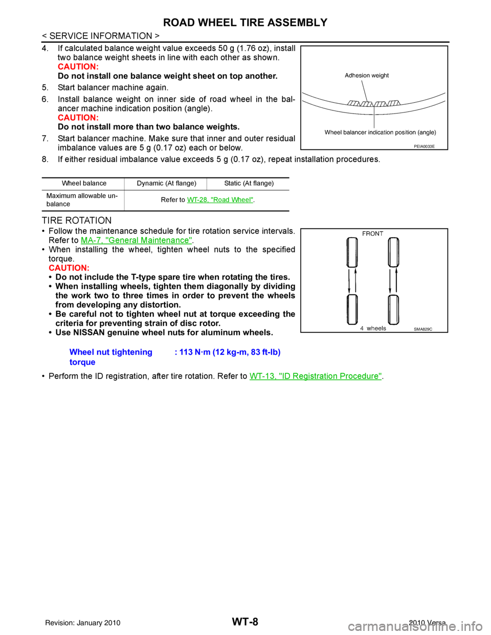
4. If calculated balance weight value exceeds 50 g (1.76 oz), installtwo balance weight sheets in line with each other as shown.
CAUTION:
Do not install one balance weight sheet on top another.
5. Start balancer machine again.
6. Install balance weight on inner side of road wheel in the bal- ancer machine indication position (angle).
CAUTION:
Do not install more than two balance weights.
7. Start balancer machine. Make sure that inner and outer residual imbalance values are 5 g (0.17 oz) each or below.
8. If either residual imbalance value exceeds 5 g (0.17 oz), repeat installation procedures.
TIRE ROTATION
• Follow the maintenance schedule for tire rotation service intervals.
Refer to MA-7, "
General Maintenance".
• When installing the wheel, tighten wheel nuts to the specified
torque.
CAUTION:
• Do not include the T-type spare tire when rotating the tires.
• When installing wheels, tighten them diagonally by dividing
the work two to three times in order to prevent the wheels
from developing any distortion.
• Be careful not to tighten wheel nut at torque exceeding the criteria for preventing strain of disc rotor.
• Use NISSAN genuine wheel nuts for aluminum wheels.
• Perform the ID registration, after tire rotation. Refer to WT-13, "
ID Registration Procedure".
Wheel balance Dynamic (At flange) Static (At flange)
Maximum allowable un-
balance Refer to
WT-28, "
Road Wheel".
PEIA0033E
Wheel nut tightening
torque : 113 N·m (12 kg-m, 83 ft-lb)
SMA829C
Revision: January 20102010 Versa
Page 3691 of 3745
WT-14
< SERVICE INFORMATION >
TROUBLE DIAGNOSES
6. Inflate all tires to proper pressure. Refer to WT-28, "Tire" .
Transmitter Wake Up OperationINFOID:0000000005397099
NOTE:
This procedure must be done after replacement of a low tire pressure warning transmitter or BCM.
New replacement transmitters are provided "asleep" and must first be "woken up" using Transmitter
Activation Tool J-45295 before ID registration can be performed.
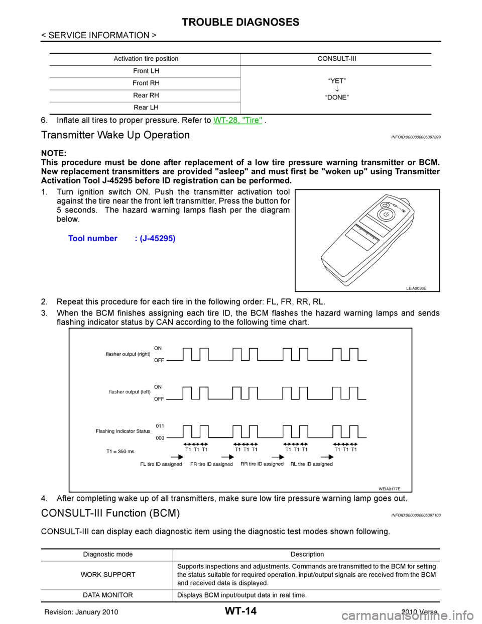
1. Turn ignition switch ON. Push the transmitter activation tool against the tire near the front left transmitter. Press the button for
5 seconds. The hazard warning lamps flash per the diagram
below.
2. Repeat this procedure for each tire in the following order: FL, FR, RR, RL.
3. When the BCM finishes assigning each tire ID, the BCM flashes the hazard warning lamps and sends flashing indicator status by CAN according to the following time chart.
4. After completing wake up of all transmitters, make sure low tire pressure warning lamp goes out.
CONSULT-III Function (BCM)INFOID:0000000005397100
CONSULT-III can display each diagnostic item us ing the diagnostic test modes shown following.
Activation tire position CONSULT-III
Front LH “YET”↓
“DONE”
Front RH
Rear RHRear LH
Tool number : (J-45295)
LEIA0036E
WEIA0177E
Diagnostic mode Description
WORK SUPPORT Supports inspections and adjustments. Commands are transmitted to the BCM for setting
the status suitable for required operation, input/output signals are received from the BCM
and received data is displayed.
DATA MONITOR Displays BCM input/output data in real time.
Revision: January 20102010 Versa
Page 3698 of 3745
TROUBLE DIAGNOSIS FOR SELF-DIAGNOSTIC ITEMS
WT-21
< SERVICE INFORMATION >
C
D F
G H
I
J
K L
M A
B
WT
N
O P
Can ID registration of all transmitters be completed?
YES >> GO TO 3.
NO >> GO TO WT-20, "
Data from Transmitter Not Being Received".
3.DRIVE VEHICLE
1. Drive at a speed of 40 km/h (25 MPH) or more fo r 3 minutes, and then drive the vehicle at any speed for
10 minutes.
2. Check all tire pressures with CONSULT-III within 5 minutes.
Does
“DATA MONITOR ITEM” display tire pressure as normal without any warning lamp?
YES >> Inspection End.
NO >> Replace malfunctioning transmitter, and perform Step 3 again. Refer to WT-26, "
Transmitter
(Pressure Sensor)".
Transmitter Pressure MalfunctionINFOID:0000000005397107
MALFUNCTION CODE NO. 35, 36, 37 OR 38 (DTC C1716, C1717, C1718 OR C1719)
1.CHECK ALL TIRE PRESSURES
Check all tire pressures. Refer to WT-28, "
Tire".
Are there any tires with pressure of 64 psi or more?
YES >> Adjust tire pressure to specified value.
NO >> GO TO 2.
2.ID REGISTRATION AND VEHICLE DRIVING
1. Carry out ID registration of all transmitters. Refer to WT-13, "
ID Registration Procedure".
2. Drive at a speed of 40 km/h (25 MPH) or more for several minutes without stopping.
3. Check all tire pressures with CONSULT-III within 15 minutes after vehicle speed becomes 17 km/h (11 MPH).
Does
“DATA MONITOR ITEM” display 64 psi or more?
YES >> Replace transmitter. Refer to WT-26, "Transmitter (Pressure Sensor)". GO TO 3.
NO >> GO TO 3.
3.ID REGISTRATION AND VEHICLE DRIVING
1. Carry out ID registration of all transmitters. Refer to WT-13, "
ID Registration Procedure".
2. Drive at a speed of 40 km/h (25 MPH) or more fo r 3 minutes, and then drive the vehicle at any speed for
10 minutes.
3. Check all tire pressures with CONSULT-III within 5 minutes.
Does
“DATA MONITOR ITEM” display tire pressure as normal without any warning lamp?
YES >> Inspection End.
NO >> GO TO the inspection applicable to DTC.
Vehicle Speed SignalINFOID:0000000005397108
MALFUNCTION CODE NO. 52 (DTC C1729)
1.SELF-DIAGNOSTIC RESULT CHECK
Using CONSULT-III, check display contents in self-diagnostic results.
Is " CAN COMM CIRCUIT" displayed in the self-diagnosis display items?
YES >> Malfunction in CAN communication system. GO TO LAN-13, "CAN Diagnosis with CONSULT-III".
NO >> GO TO 2.
2.CHECK BCM
Perform BCM diagnosis. Refer to BCS-17, "
CONSULT-III Function (BCM)".
Inspection results OK?
OK >> Perform Vehicle Speed Sensor Inspection. Refer to EC-342, "Diagnosis Procedure" (HR16DE) or
EC-888, "
Diagnosis Procedure" (MR18DE).
NG >> Replace BCM. Refer to BCS-19, "
Removal and Installation of BCM".
Revision: January 20102010 Versa