2010 NISSAN TIIDA parking brake
[x] Cancel search: parking brakePage 1220 of 3745
DI-10
< SERVICE INFORMATION >
COMBINATION METERS
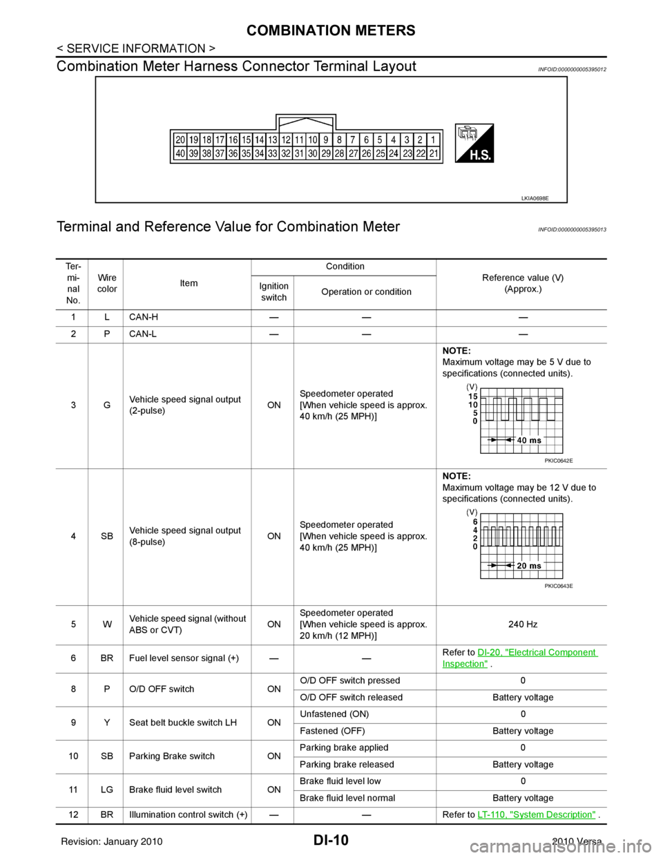
Combination Meter Harness Connector Terminal Layout
INFOID:0000000005395012
Terminal and Reference Va lue for Combination MeterINFOID:0000000005395013
LKIA0698E
Te r -
mi-nal
No. Wire
color Item Condition
Reference value (V)(Approx.)
Ignition
switch Operation or condition
1LCAN-H —— —
2PCAN-L —— —
3G Vehicle speed signal output
(2-pulse) ONSpeedometer operated
[When vehicle speed is approx.
40 km/h (25 MPH)] NOTE:
Maximum voltage may be 5 V due to
specifications (connected units).
4SB Vehicle speed signal output
(8-pulse) ONSpeedometer operated
[When vehicle speed is approx.
40 km/h (25 MPH)] NOTE:
Maximum voltage may be 12 V due to
specifications (connected units).
5W Vehicle speed signal (without
ABS or CVT) ONSpeedometer operated
[When vehicle speed is approx.
20 km/h (12 MPH)] 240 Hz
6 BR Fuel level sensor signal (+) — —Refer to DI-20, "
Electrical Component
Inspection" .
8 P O/D OFF switch ONO/D OFF switch pressed
0
O/D OFF switch released Battery voltage
9 Y Seat belt buckle switch LH ON Unfastened (ON)
0
Fastened (OFF) Battery voltage
10 SB Parking Brake switch ONParking brake applied
0
Parking brake released Battery voltage
11 LG Brake fluid level switch ON Brake fluid level low
0
Brake fluid level normal Battery voltage
12 BR Illumination control switch (+) — —Refer to LT- 11 0 , "
System Description" .
PKIC0642E
PKIC0643E
Revision: January 20102010 Versa
Page 1224 of 3745

DI-14
< SERVICE INFORMATION >
COMBINATION METERS
NOTE:
Some items are not available due to vehicle specification.
*: The monitor will indicate “OFF” even though the brake warning lamp is on if either of the following conditions exist.
• The parking brake is engaged
• The brake fluid level is low
Trouble DiagnosisINFOID:0000000005395016
HOW TO PERFORM TROUBLE DIAGNOSIS
1. Confirm the symptom or customer complaint.
2. Perform preliminary check. Refer to "PRELIMINARY CHECK" .
3. According to the symptom chart, repair or replace the cause of the malfunction. Refer to DI-15, "
Symptom
Chart" .
4. Does the meter operate normally? If so, GO TO 5. If not, GO TO 2.
5. Inspection End.
PRELIMINARY CHECK
1.CHECK SELF-DIAGNOSIS OPERAT ION OF COMBINATION METER
Perform self-diagnosis of combination meter. Refer to DI-11, "
Self-Diagnosis Mode of Combination Meter" .
Does self
-diagnosis mode operate?
TURN IND [ON/OFF] X Indicates [ON/OFF] condition of turn indicator.
OIL W/L [ON/OFF] X Indicates [ON/OFF] condition of oil pressure warning lamp.
VDC/TCS IND [ON/OFF] X Indicates [ON/OFF] condition of VDC OFF indicator lamp.
ABS W/L [ON/OFF] X Indicates [ON/OFF] condition of ABS warning lamp.
SLIP IND [ON/OFF] X Indicates [ON/OFF] condition of SLIP indicator lamp.
BRAKE W/L [ON/OFF] X Indicates [ON/OFF] condition of brake warning lamp.*
KEY G W/L [ON/OFF] X Indicates [ON/OFF] condition of KEY warning lamp (green).
KEY R W/L [ON/OFF] X Indicates [ON/OFF] condition of KEY warning lamp (red).
KEY KNOB W/L [ON/OFF] X Indicates [ON/OFF] condition of LOCK warning lamp.
PNP P SW [ON/OFF] XX Indicates [ON/OFF] condition of inhibitor P switch.
PNP N SW [ON/OFF] XX Indicates [ON/OFF] condition of inhibitor N switch.
O/D OFF SW [ON/OFF] X Indicates [ON/OFF] condition of O/D OFF switch.
BRAKE SW [ON/OFF] X Indicates [ON/OFF] condition of parking brake switch.
P RANGE IND [ON/OFF] XXIndicates [ON/OFF] condition of A/T or CVT shift P range indi-
cator.
R RANGE IND [ON/OFF] XXIndicates [ON/OFF] condition of A/T or CVT shift R range indi-
cator.
N RANGE IND [ON/OFF] XXIndicates [ON/OFF] condition of A/T or CVT shift N range indi-
cator.
D RANGE IND [ON/OFF] XXIndicates [ON/OFF] condition of A/T or CVT shift D range indi-
cator.
2 RANGE IND [ON/OFF] XX Indicates [ON/OFF] condition of A/T shift 2 range indicator.
L RANGE IND [ON/OFF] XX Indicates [ON/OFF] condition of CVT shift L range indicator.
1 RANGE IND [ON/OFF] XX Indicates [ON/OFF] condition of A/T shift 1 range indicator.
CRUISE IND [ON/OFF] X Indicates [ON/OFF] condition of CRUISE indicator.
SET IND [ON/OFF] X Indicates [ON/OFF] condition of SET indicator.
O/D OFF W/L [ON/OFF] X Indicates [ON/OFF] condition of O/D OFF indicator lamp.
EPS W/L [ON/OFF] X Indicates [ON/OFF] condition of EPS warning lamp.
Display item [Unit]
MAIN
SIGNALS SELECTION
FROM MENU Contents
Revision: January 20102010 Versa
Page 1253 of 3745
WARNING CHIMEDI-43
< SERVICE INFORMATION >
C
DE
F
G H
I
J
L
M A
B
DI
N
O P
WARNING CHIME
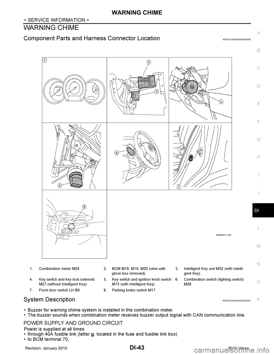
Component Parts and Har ness Connector LocationINFOID:0000000005395039
System DescriptionINFOID:0000000005395040
• Buzzer for warning chime system is installed in the combination meter.
• The buzzer sounds when combination meter receives buzzer output signal with CAN communication line.
POWER SUPPLY AND GROUND CIRCUIT
Power is supplied at all times
• through 40A fusible link (letter g, located in the fuse and fusible link box)
• to BCM terminal 70,
1. Combination meter M24 2. BCM M18, M19, M20 (view with
glove box removed) 3. Intelligent Key unit M52 (with Intelli-
gent Key)
4. Key switch and key lock solenoid M27 (without Intelligent Key) 5. Key switch and ignition knob switch
M73 (with Intelligent Key) 6. Combination switch (lighting switch)
M28
7. Front door switch LH B8 8. Parking brake switch M17
AWMIA0117ZZ
Revision: January 20102010 Versa
Page 1255 of 3745
WARNING CHIMEDI-45
< SERVICE INFORMATION >
C
DE
F
G H
I
J
L
M A
B
DI
N
O P
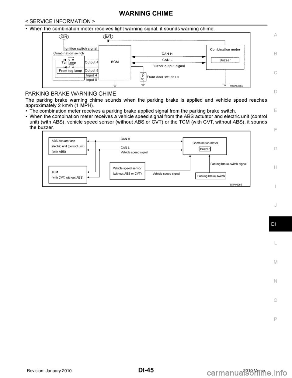
• When the combination meter receives light warning signal, it sounds warning chime.
PARKING BRAKE WARNING CHIME
The parking brake warning chime sounds when the parking brake is applied and vehicle speed reaches
approximately 2 km/h (1 MPH).
• The combination meter receives a parking brake applied signal from the parking brake switch.
• When the combination meter receives a vehicle speed si gnal from the ABS actuator and electric unit (control
unit) (with ABS), vehicle speed sensor (without ABS or CVT) or the TCM (with CVT, without ABS), it sounds
the buzzer.
WKIA5465E
LKIA0906E
Revision: January 20102010 Versa
Page 1259 of 3745
WARNING CHIMEDI-49
< SERVICE INFORMATION >
C
DE
F
G H
I
J
L
M A
B
DI
N
O P
1.CHECK BCM
Perform self-diagnosis of BCM. Refer to DI-47, "
CONSULT-III Function (BCM)".
Self
-diagnostic results content
No malfunction detected>> GO TO 2.
Malfunction detected>> Check applicable parts, and repair or replace corresponding parts.
2.CHECK COMBINATION METER
Perform self-diagnosis of combination meter. Refer to DI-13, "
CONSULT-III Function (METER/M&A)".
Self
-diagnostic results content
No malfunction detected>> Inspection End.
Malfunction detected>> Check applicable parts, and repair or replace corresponding parts.
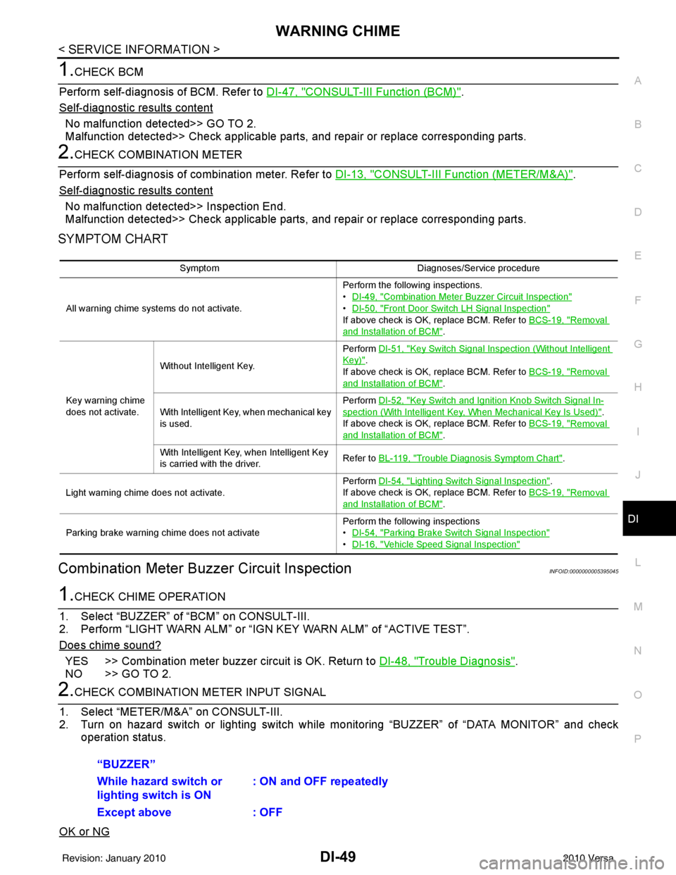
SYMPTOM CHART
Combination Meter Buzzer Circuit InspectionINFOID:0000000005395045
1.CHECK CHIME OPERATION
1. Select “BUZZER” of “BCM” on CONSULT-III.
2. Perform “LIGHT WARN ALM” or “IGN KEY WARN ALM” of “ACTIVE TEST”.
Does chime sound?
YES >> Combination meter buzzer circuit is OK. Return to DI-48, "Trouble Diagnosis".
NO >> GO TO 2.
2.CHECK COMBINATION METER INPUT SIGNAL
1. Select “METER/M&A” on CONSULT-III.
2. Turn on hazard switch or lighting switch while monitoring “BUZZER” of “DATA MONITOR” and check
operation status.
OK or NG
Symptom Diagnoses/Service procedure
All warning chime systems do not activate. Perform the following inspections.
•
DI-49, "
Combination Meter Buzzer Circuit Inspection"
•DI-50, "Front Door Switch LH Signal Inspection"
If above check is OK, replace BCM. Refer to BCS-19, "Removal
and Installation of BCM".
Key warning chime
does not activate. Without Intelligent Key.
Perform
DI-51, "
Key Switch Signal Inspection (Without Intelligent
Key)".
If above check is OK, replace BCM. Refer to BCS-19, "
Removal
and Installation of BCM".
With Intelligent Key, when mechanical key
is used. Perform
DI-52, "
Key Switch and Ignition Knob Switch Signal In-
spection (With Intelligent Key, When Mechanical Key Is Used)".
If above check is OK, replace BCM. Refer to BCS-19, "
Removal
and Installation of BCM".
With Intelligent Key, when Intelligent Key
is carried with the driver. Refer to BL-119, "
Trouble Diagnosis Symptom Chart".
Light warning chime does not activate. Perform
DI-54, "
Lighting Switch Signal Inspection".
If above check is OK, replace BCM. Refer to BCS-19, "
Removal
and Installation of BCM".
Parking brake warning chime does not activate Perform the following inspections
•
DI-54, "
Parking Brake Switch Signal Inspection"
•DI-16, "Vehicle Speed Signal Inspection"
“BUZZER”
While hazard switch or
lighting switch is ON : ON and OFF repeatedly
Except above : OFF
Revision: January 20102010 Versa
Page 1264 of 3745
DI-54
< SERVICE INFORMATION >
WARNING CHIME
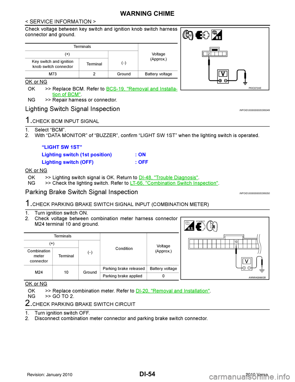
Check voltage between key switch and ignition knob switch harness
connector and ground.
OK or NG
OK >> Replace BCM. Refer to BCS-19, "Removal and Installa-
tion of BCM".
NG >> Repair harness or connector.
Lighting Switch Signal InspectionINFOID:0000000005395049
1.CHECK BCM INPUT SIGNAL
1. Select “BCM”.
2. With “DATA MONITOR” of “BUZZER”, confirm “LIG HT SW 1ST” when the lighting switch is operated.
OK or NG
OK >> Lighting switch signal is OK. Return to DI-48, "Trouble Diagnosis".
NG >> Check the lighting switch. Refer to LT-66, "
Combination Switch Inspection".
Parking Brake Switch Signal InspectionINFOID:0000000005395050
1.CHECK PARKING BRAKE SWITCH SIGNAL INPUT (COMBINATION METER)
1. Turn ignition switch ON.
2. Check voltage between combination meter harness connector M24 terminal 10 and ground.
OK or NG
OK >> Replace combination meter. Refer to DI-20, "Removal and Installation".
NG >> GO TO 2.
2.CHECK PARKING BRAKE SWITCH CIRCUIT
1. Turn ignition switch OFF.
2. Disconnect combination meter connector and parking brake switch connector.
Te r m i n a l s
Vo l ta g e
(Approx.)
(+)
(−)
Key switch and ignition
knob switch connector Te r m i n a l
M73 2Ground Battery voltage
PKIC0724E
“LIGHT SW 1ST”
Lighting switch ( 1st position) : ON
Lighting switch (OFF) : OFF
Te r m i n a l s
ConditionVoltag e
(Approx.)
(+)
(−)
Combination
meter
connector Te r m i n a l
M24 10 Ground Parking brake released Battery voltage
Parking brake applied 0
AWMIA0066GB
Revision: January 20102010 Versa
Page 1265 of 3745
WARNING CHIMEDI-55
< SERVICE INFORMATION >
C
DE
F
G H
I
J
L
M A
B
DI
N
O P
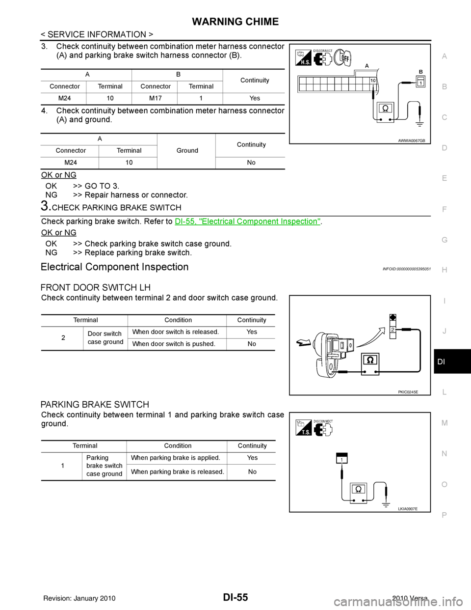
3. Check continuity between combination meter harness connector (A) and parking brake switch harness connector (B).
4. Check continuity between combination meter harness connector (A) and ground.
OK or NG
OK >> GO TO 3.
NG >> Repair harness or connector.
3.CHECK PARKING BRAKE SWITCH
Check parking brake switch. Refer to DI-55, "
Electrical Component Inspection".
OK or NG
OK >> Check parking brake switch case ground.
NG >> Replace parking brake switch.
Electrical Component InspectionINFOID:0000000005395051
FRONT DOOR SWITCH LH
Check continuity between terminal 2 and door switch case ground.
PARKING BRAKE SWITCH
Check continuity between terminal 1 and parking brake switch case
ground.
AB Continuity
Connector Terminal Connector Terminal
M241 0M 17 1 Y es
A GroundContinuity
Connector Terminal
M24 10 No
AWMIA0067GB
TerminalConditionContinuity
2 Door switch
case ground When door switch is released. Yes
When door switch is pushed. No
PKIC0245E
Terminal
ConditionContinuity
1 Parking
brake switch
case ground When parking brake is applied. Yes
When parking brake is released. No
LKIA0907E
Revision: January 20102010 Versa
Page 1291 of 3745
![NISSAN TIIDA 2010 Service Repair Manual EC-26
< BASIC INSPECTION >[HR16DE]
INSPECTION AND ADJUSTMENT
• Each time electric throttle control actuator or ECM is replaced.
• Idle speed or ignition timing is out of specification.
IDLE AIR VO NISSAN TIIDA 2010 Service Repair Manual EC-26
< BASIC INSPECTION >[HR16DE]
INSPECTION AND ADJUSTMENT
• Each time electric throttle control actuator or ECM is replaced.
• Idle speed or ignition timing is out of specification.
IDLE AIR VO](/manual-img/5/57397/w960_57397-1290.png)
EC-26
< BASIC INSPECTION >[HR16DE]
INSPECTION AND ADJUSTMENT
• Each time electric throttle control actuator or ECM is replaced.
• Idle speed or ignition timing is out of specification.
IDLE AIR VOLUME LEARNING
: Special Repair RequirementINFOID:0000000005398245
1.PRECONDITIONING
Make sure that all of the following conditions are satisfied.
Learning will be cancelled if any of the follo wing conditions are missed for even a moment.
• Battery voltage: More than 12.9 V (At idle)
• Engine coolant temperature: 70 - 100 °C (158 - 212° F)
• Selector lever: P or N (A/T), Neutral (M/T)
• Electric load switch: OFF (Air conditioner, headlamp, rear window defogger)
On vehicles equipped with daytime light systems, if the parking brake is applied before the engine is
started the headlamp will not be illuminated.
• Steering wheel: Neutral (Straight-ahead position)
• Vehicle speed: Stopped
• Transmission: Warmed-up
- A/T models
• With CONSULT-III: Drive vehicle until “FLUID TEMP SE” in “DATA MONITOR” mode of “TRANSMISSION”
system indicates less than 0.9 V.
• Without CONSULT-III: Drive vehicle for 10 minutes.
- M/T models
• Drive vehicle for 10 minutes.
Do you have CONSULT-III?
YES >> GO TO 2.
NO >> GO TO 3.
2.IDLE AIR VOLUME LEARNING
With CONSULT-III
1. Perform Accelerator Pedal Released Position Learning. Refer to EC-25, "
ACCELERATOR PEDAL
RELEASED POSITION LEARNING : Special Repair Requirement".
2. Perform Throttle Valve Closed Position Learning. Refer to EC-25, "
THROTTLE VALVE CLOSED POSI-
TION LEARNING : Special Repair Requirement".
3. Start engine and warm it up to normal operating temperature.
4. Select “IDLE AIR VOL LEARN” in “WORK SUPPORT” mode.
5. Touch “START” and wait 20 seconds.
Is
“CMPLT” displayed on CONSULT-III screen?
YES >> GO TO 4.
NO >> GO TO 5.
3.IDLE AIR VOLUME LEARNING
Without CONSULT-III
NOTE:
• It is better to count the ti me accurately with a clock.
• It is impossible to switch the di agnostic mode when an accelerator pedal position sensor circuit has
a malfunction.
1. Perform Accelerator Pedal Released Position Learning. Refer to EC-25, "
ACCELERATOR PEDAL
RELEASED POSITION LEARNING : Special Repair Requirement".
2. Perform Throttle Valve Closed Position Learning. Refer to EC-25, "
THROTTLE VALVE CLOSED POSI-
TION LEARNING : Special Repair Requirement".
3. Start engine and warm it up to normal operating temperature.
4. Turn ignition switch OFF and wait at least 10 seconds.
5. Confirm that accelerator pedal is fully releas ed, turn ignition switch ON and wait 3 seconds.
6. Repeat the following procedure quickly five times within 5 seconds.
- Fully depress the accelerator pedal.
- Fully release the accelerator pedal.
7. Wait 7 seconds, fully depress the accelerator pedal and keep it for approx. 20 seconds until the MIL stops
blinking and turned ON.
8. Fully release the accelerator pedal within 3 seconds after the MIL turned ON.
Revision: January 20102010 Versa