2010 NISSAN TIIDA heating
[x] Cancel search: heatingPage 2180 of 3745
![NISSAN TIIDA 2010 Service Repair Manual DTC P1217 ENGINE OVER TEMPERATUREEC-915
< SERVICE INFORMATION > [MR18DE]
C
D
E
F
G H
I
J
K L
M A
EC
NP
O
2.CHECK COOLING FAN OPERATION
With CONSULT-III
1. Turn ignition switch ON.
2. Perform “COOL NISSAN TIIDA 2010 Service Repair Manual DTC P1217 ENGINE OVER TEMPERATUREEC-915
< SERVICE INFORMATION > [MR18DE]
C
D
E
F
G H
I
J
K L
M A
EC
NP
O
2.CHECK COOLING FAN OPERATION
With CONSULT-III
1. Turn ignition switch ON.
2. Perform “COOL](/manual-img/5/57397/w960_57397-2179.png)
DTC P1217 ENGINE OVER TEMPERATUREEC-915
< SERVICE INFORMATION > [MR18DE]
C
D
E
F
G H
I
J
K L
M A
EC
NP
O
2.CHECK COOLING FAN OPERATION
With CONSULT-III
1. Turn ignition switch ON.
2. Perform “COOLING FAN” in “ACTIVE TEST” mode with CONSULT-III.
3. Make sure that cooling fan operates at each speed.
OK or NG
OK >> GO TO 4.
NG >> GO TO 8.
3.CHECK COOLING FAN OPERATION
Without CONSULT-III
1. Perform IPDM E/R auto active test and check cooling fan operation. Refer to PG-20, "
Auto Active Test".
2. Make sure that cooling fan operates at each speed.
OK or NG
OK >> GO TO 4.
NG >> GO TO 8.
4.CHECK COOLING SYSTEM FOR LEAK
Refer to CO-36, "
Inspection".
OK or NG
OK >> GO TO 5.
NG >> Check the following for leak. Refer to CO-36, "
Inspection".
•Hose
• Radiator
• Water pump
5.CHECK RADIATOR CAP
Refer to CO-39, "
Checking Radiator Cap".
OK or NG
OK >> GO TO 6.
NG >> Replace radiator cap.
6.CHECK COMPONENT PARTS
Check the following.
• Thermostat. (Refer to CO-46
.)
• Water control valve. (Refer to CO-48
.)
• Engine coolant temperature sensor. (Refer to EC-684
.)
OK or NG
OK >> GO TO 7.
NG >> Replace malfunctioning component.
7.CHECK MAIN 13 CAUSES
If the cause cannot be isolated, go to EC-917, "
Main 13 Causes of Overheating".
>> INSPECTION END
8.CHECK IPDM E/R POWER SUPPLY CIRCUIT
1. Turn ignition switch OFF.
2. Disconnect IPDM E/R harness connector E44.
Revision: January 20102010 Versa
Page 2182 of 3745
![NISSAN TIIDA 2010 Service Repair Manual DTC P1217 ENGINE OVER TEMPERATUREEC-917
< SERVICE INFORMATION > [MR18DE]
C
D
E
F
G H
I
J
K L
M A
EC
NP
O
Cooling fan motor terminal 2 and IPDM E/R terminal 24.
Cooling fan motor terminal 3 and IPDM E/ NISSAN TIIDA 2010 Service Repair Manual DTC P1217 ENGINE OVER TEMPERATUREEC-917
< SERVICE INFORMATION > [MR18DE]
C
D
E
F
G H
I
J
K L
M A
EC
NP
O
Cooling fan motor terminal 2 and IPDM E/R terminal 24.
Cooling fan motor terminal 3 and IPDM E/](/manual-img/5/57397/w960_57397-2181.png)
DTC P1217 ENGINE OVER TEMPERATUREEC-917
< SERVICE INFORMATION > [MR18DE]
C
D
E
F
G H
I
J
K L
M A
EC
NP
O
Cooling fan motor terminal 2 and IPDM E/R terminal 24.
Cooling fan motor terminal 3 and IPDM E/R terminal 23.
Cooling fan motor terminal 4 and ground.
Refer to wiring diagram.
3. Also check harness for short to ground and short to power.
OK or NG
OK >> GO TO 15.
NG >> GO TO 14.
14.DETECT MALFUNCTIONING PART
Check the following.
• Harness for open or short between cooling fan motor and IPDM E/R
• Harness for open or short between cooling fan motor and ground
>> Repair open circuit or short to ground or short to power in harness or connectors.
15.CHECK COOLING FAN MOTOR
Refer to EC-918, "
Component Inspection".
OK or NG
OK >> GO TO 16.
NG >> Replace cooling fan motor.
16.CHECK INTERMITTENT INCIDENT
Perform EC-632
.
OK or NG
OK >> Replace IPDM E/R. Refer to PG-28, "Removal and Installation of IPDM E/R".
NG >> Repair or replace harness or connector.
Main 13 Causes of OverheatingINFOID:0000000005532780
Continuity should exist.
Engine Step Inspection item EquipmentStandardReference
OFF 1
• Blocked radiator
• Blocked condenser
• Blocked radiator grille
• Blocked bumper • Visual
No blocking —
2 • Coolant mixture • Coolant tester See MA-15, "
Anti-freeze Coolant Mixture Ratio".
3 • Coolant level • VisualCoolant up to MAX level in
reservoir tank and radiator
filler neck
See
CO-36, "
Inspection".
4 • Radiator cap • Pressure tester See CO-39, "
Checking Radiator Cap".
ON*
25 • Coolant leaks • VisualNo leaks See CO-36, "Inspection".
ON*
26 • Thermostat • Touch the upper and
lower radiator hoses Both hoses should be hot See CO-46, and
CO-48
ON*17 • Cooling fan • CONSULT-IIIOperating See trouble diagnosis for
DTC P1217 (
EC-914, "Di-
agnosis Procedure").
OFF 8 • Combustion gas leak • Color checker chemical
tester 4 Gas analyzer Negative
—
ON*
39 • Coolant temperature
gauge •Visual
Gauge less than 3/4 when
driving —
• Coolant overflow to res- ervoir tank •Visual No overflow during driving
and idling See
CO-36, "Changing
Engine Coolant".
Revision: January 20102010 Versa
Page 2188 of 3745
![NISSAN TIIDA 2010 Service Repair Manual DTC P1421 COLD START CONTROLEC-923
< SERVICE INFORMATION > [MR18DE]
C
D
E
F
G H
I
J
K L
M A
EC
NP
O
DTC P1421 COLD START CONTROL
DescriptionINFOID:0000000005532792
ECM controls ignition timing and eng NISSAN TIIDA 2010 Service Repair Manual DTC P1421 COLD START CONTROLEC-923
< SERVICE INFORMATION > [MR18DE]
C
D
E
F
G H
I
J
K L
M A
EC
NP
O
DTC P1421 COLD START CONTROL
DescriptionINFOID:0000000005532792
ECM controls ignition timing and eng](/manual-img/5/57397/w960_57397-2187.png)
DTC P1421 COLD START CONTROLEC-923
< SERVICE INFORMATION > [MR18DE]
C
D
E
F
G H
I
J
K L
M A
EC
NP
O
DTC P1421 COLD START CONTROL
DescriptionINFOID:0000000005532792
ECM controls ignition timing and engine idle speed when engine is started with prewarming up condition.
This control promotes the activation of three way catalyst by heating the catalyst and reduces emissions.
On Board Diagnosis LogicINFOID:0000000005532793
DTC Confirmation ProcedureINFOID:0000000005532794
NOTE:
• If DTC Confirmation Procedure has been previously conduc
ted, always turn ignition switch OFF and wait at
least 10 seconds before conducting the next test.
• If DTC P1421 is displayed with other DTC, firs t perform the trouble diagnosis for other DTC.
TESTING CONDITION:
Before performing the following procedure, confirm that battery voltage is more than 11 V at idle.
WITH CONSULT-III
1. Turn ignition switch OFF and wait at least 10 seconds.
2. Turn ignition switch ON.
3. Select “DATA MONITOR” mode with CONSULT-III.
4. Check that the “COOLAN TEMP/S” indication is between 4°C (39° F) and 36 °C (97° F).
If “COOLAN TEMP/S” indication is within the specified value, go to the following step.
If “COOLAN TEMP/S” indication is out of the specified value, cool engine down or warm engine up and go
to step 1.
5. Start engine and let it idle for 5 minutes.
6. Check 1st trip DTC.
7. If 1st trip DTC is detected, go to EC-923, "
Diagnosis Procedure".
Diagnosis ProcedureINFOID:0000000005532795
1.PERFORM IDLE AIR VOLUME LEARNING
Perform EC-580, "
Idle Air Volume Learning".
Is Idle Air Volume Learning carried out successfully?
Ye s o r N o
Yes >> GO TO 2.
No >> Follow the instruction of Idle Air Volume Learning.
2.CHECK INTAKE SYSTEM
Check for the cause of intake air volume lacking. Refer to the following.
• Crushed intake air passage
• Intake air passage clogging
OK or NG
OK >> GO TO 3.
NG >> Repair or replace malfunctioning part
3.CHECK FUEL INJECTION SYSTEM FUNCTION
Perform EC-758, "
DTC Confirmation Procedure" for DTC P0171.
OK or NG
OK >> GO TO 4.
DTC No. Trouble diagnosis name DTC detecting conditionPossible cause
P1421
1421 Cold start emission reduction
strategy monitoring ECM does not control ignition timing and engine
idle speed properly when engine is started with
prewarming up condition. • Lack of intake air volume
• Fuel injection system
•ECM
Revision: January 20102010 Versa
Page 2693 of 3745

SERVICE INFORMATION FOR ELECTRICAL INCIDENTGI-27
< SERVICE INFORMATION >
C
DE
F
G H
I
J
K L
M B
GI
N
O P
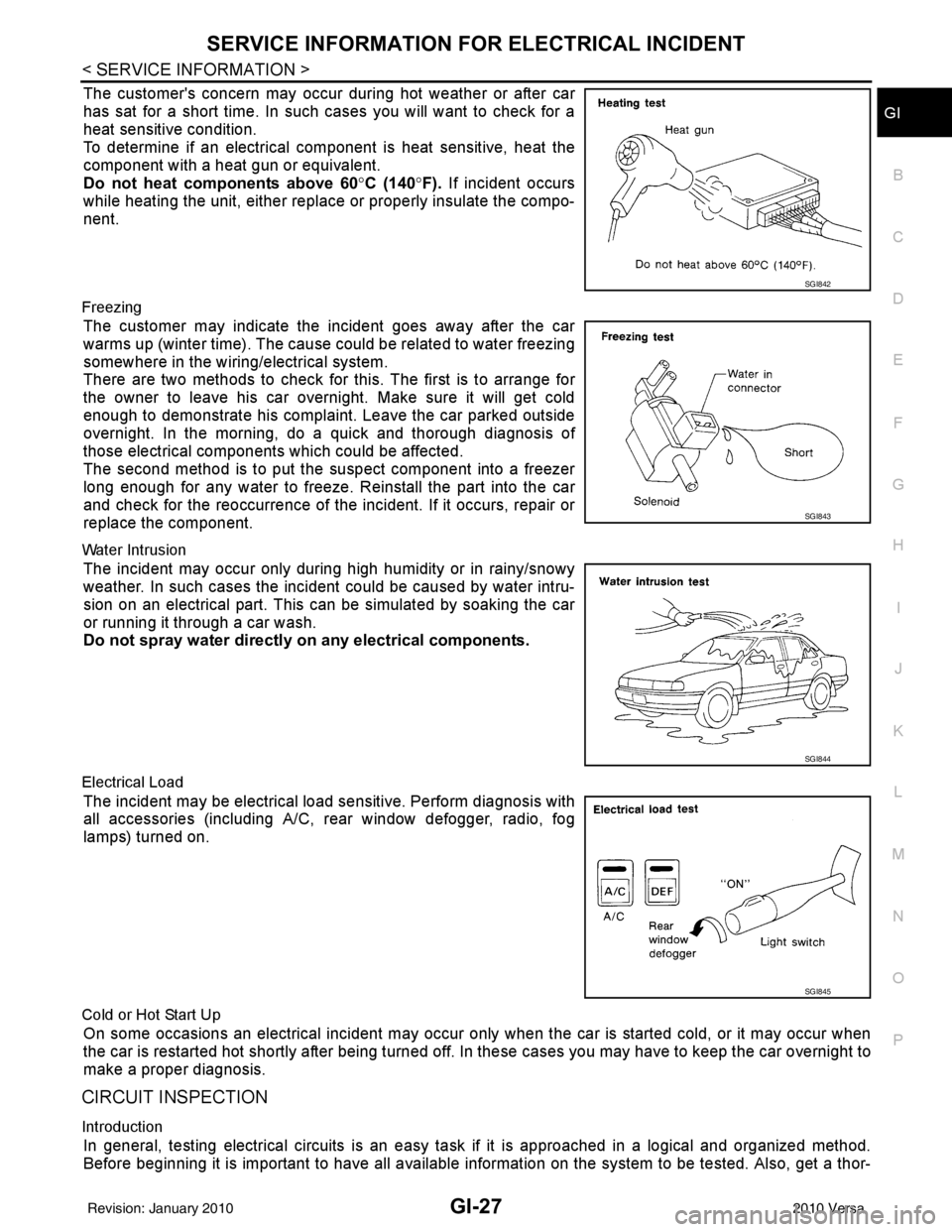
The customer's concern may occur during hot weather or after car
has sat for a short time. In such cases you will want to check for a
heat sensitive condition.
To determine if an electrical com ponent is heat sensitive, heat the
component with a heat gun or equivalent.
Do not heat components above 60 °C (140° F). If incident occurs
while heating the unit, either replace or properly insulate the compo-
nent.
Freezing
The customer may indicate the incident goes away after the car
warms up (winter time). The cause could be related to water freezing
somewhere in the wiring/electrical system.
There are two methods to check for this. The first is to arrange for
the owner to leave his car overnight. Make sure it will get cold
enough to demonstrate his complaint. Leave the car parked outside
overnight. In the morning, do a quick and thorough diagnosis of
those electrical components which could be affected.
The second method is to put the suspect component into a freezer
long enough for any water to freeze. Reinstall the part into the car
and check for the reoccurrence of the incident. If it occurs, repair or
replace the component.
Water Intrusion
The incident may occur only during high humidity or in rainy/snowy
weather. In such cases the incident could be caused by water intru-
sion on an electrical part. This c an be simulated by soaking the car
or running it through a car wash.
Do not spray water directly on any electrical components.
Electrical Load
The incident may be electrical load sensitive. Perform diagnosis with
all accessories (including A/C, rear window defogger, radio, fog
lamps) turned on.
Cold or Hot Start Up
On some occasions an electrical incident may occur only when the car is started cold, or it may occur when
the car is restarted hot shortly after being turned off. In these cases you may have to keep the car overnight to
make a proper diagnosis.
CIRCUIT INSPECTION
Introduction
In general, testing electrical circuits is an easy ta sk if it is approached in a logical and organized method.
Before beginning it is important to have all available information on the system to be tested. Also, get a thor-
SGI842
SGI843
SGI844
SGI845
Revision: January 20102010 Versa
Page 3280 of 3745

MTC-1
AIR CONDITIONER
C
DE
F
G H
I
K L
M
SECTION MTC
A
B
MTC
N
O P
CONTENTS
MANUAL AIR CONDITIONER
SERVICE INFORMATION .. ..........................3
PRECAUTIONS .............................................. .....3
Precaution for Supplemental Restraint System
(SRS) "AIR BAG" and "SEAT BELT PRE-TEN-
SIONER" ............................................................. ......
3
Precaution Necessary for Steering Wheel Rota-
tion After Battery Disconnect ............................... ......
3
Precaution for Procedure without Cowl Top Cover ......4
Precaution for Working with HFC-134a (R-134a) ......4
General Refrigerant Precaution ................................4
Oil Precaution ............................................................5
Precaution for Refrigerant Connection ......................5
Precaution for Service of Compressor ................ ......7
Precaution for Service Equipment ....................... ......8
Precaution for Leak Detection Dye ...........................9
PREPARATION ..................................................11
HFC-134a (R-134a) Service Tool and Equipment ....11
Commercial Service Tool ........................................14
REFRIGERATION SYSTEM ..............................15
Refrigerant Cycle ................................................ ....15
Refrigerant System Protection ................................15
Component Part Location ................................... ....16
OIL ......................................................................17
Maintenance of Oil Quantity in Compressor ....... ....17
AIR CONDITIONER CONTROL .........................19
Control Operation ................................................ ....19
Discharge Air Flow ..................................................20
System Description .................................................20
TROUBLE DIAGNOSIS .....................................22
CONSULT-III Function (BCM) ............................. ....22
How to Perform Trouble Diagnosis for Quick and
Accurate Repair ......................................................
23
Component Parts and Harness Connector Loca-
tion ...................................................................... ....
23
Schematic ...............................................................26
Wiring Diagram - Heater - .......................................27
Wiring Diagram - A/C,M - .................................... ....28
Operational Check ...................................................31
Mode Door ...............................................................32
Air Mix Door .............................................................33
Intake Door ..............................................................34
Front Blower Motor Circuit .......................................34
Magnet Clutch Circuit (If Equipped) ..................... ....38
Insufficient Cooling ..................................................46
Insufficient Heating ..................................................53
Noise .......................................................................54
CONTROLLER ..................................................56
Removal and Installation .........................................56
Disassembly and Assembly .....................................57
THERMO CONTROL AMPLIFIER ....................58
Removal and Installation .........................................58
A/C UNIT ASSEMBLY ......................................59
Removal and Installation .........................................59
Disassembly and Assembly .....................................61
BLOWER MOTOR ............................................63
Removal and Installation .........................................63
INTAKE DOOR ..................................................64
Intake Door Cable Adjustment .................................64
AIR MIX DOOR .................................................65
Air Mix Door Cable Adjustment ...............................65
MODE DOOR ....................................................66
Mode Door Cable Adjustment .................................66
BLOWER FAN RESISTOR ...............................67
Removal and Installation .........................................67
HEATER CORE .................................................68
Removal and Installation .........................................68
AIR CONDITIONER FILTER .............................69
Removal and Installation .........................................69
Revision: January 20102010 Versa
Page 3302 of 3745

TROUBLE DIAGNOSISMTC-23
< SERVICE INFORMATION >
C
DE
F
G H
I
K L
M A
B
MTC
N
O P
WORK SUPPORT
Display Item List
How to Perform Trouble Diagnosis for Quick and Accurate RepairINFOID:0000000005396492
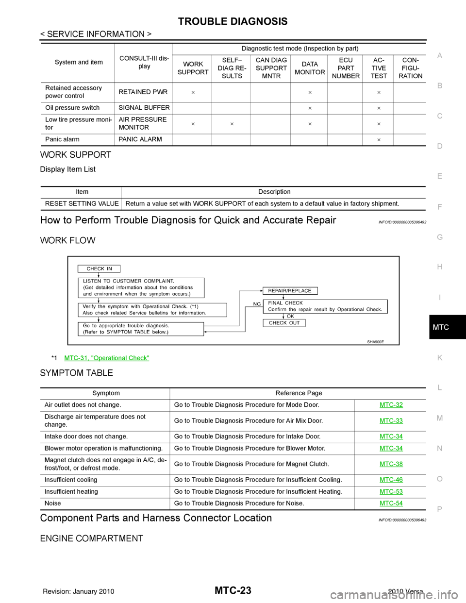
WORK FLOW
SYMPTOM TABLE
Component Parts and Har ness Connector LocationINFOID:0000000005396493
ENGINE COMPARTMENT
Retained accessory
power controlRETAINED PWR
×× ×
Oil pressure switch SIGNAL BUFFER ××
Low tire pressure moni-
tor AIR PRESSURE
MONITOR
××
× ×
Panic alarm PANIC ALARM ×
System and item
CONSULT-III dis-
play Diagnostic test mode (Inspection by part)
WORK
SUPPORT SELF
−
DIAG RE-
SULTS CAN DIAG
SUPPORT
MNTR DATA
MONITOR ECU
PA R T
NUMBER AC-
TIVE
TEST CON-
FIGU-
RATION
Item Description
RESET SETTING VALUE Return a value set with WORK SUPPORT of each system to a default value in factory shipment.
*1 MTC-31, "Operational Check"
SHA900E
Symptom Reference Page
Air outlet does not change. Go to Trouble Diagnosis Procedure for Mode Door. MTC-32
Discharge air temperature does not
change.Go to Trouble Diagnosis Procedure for Air Mix Door.
MTC-33
Intake door does not change.Go to Trouble Diagnosis Procedure for Intake Door. MTC-34
Blower motor operation is malfunctioning. Go to Trouble Diagnosis Procedure for Blower Motor. MTC-34
Magnet clutch does not engage in A/C, de-
frost/foot, or defrost mode.Go to Trouble Diagnosis Procedure for Magnet Clutch.
MTC-38
Insufficient coolingGo to Trouble Diagnosis Procedure for Insufficient Cooling. MTC-46
Insufficient heatingGo to Trouble Diagnosis Procedure for Insufficient Heating. MTC-53
NoiseGo to Trouble Diagnosis Procedure for Noise. MTC-54
Revision: January 20102010 Versa
Page 3311 of 3745

MTC-32
< SERVICE INFORMATION >
TROUBLE DIAGNOSIS
1. Turn blower control dial clockwise to "1" position. Blower should operate on low speed.
2. Turn blower control dial clockwise to "2" position, and continue checking blower speed until all speeds are
checked.
3. Leave blower on Maximum speed.
If NG, go to trouble diagnosis procedure for MTC-34, "
Front Blower Motor Circuit".
If OK, continue the check.
CHECKING DISCHARGE AIR
1. Turn mode door control dial to each position.
2. Confirm that discharge air comes out according to the air distribution table. Refer to MTC-20, "
Discharge
Air Flow".
If NG, go to trouble diagnosis procedure for MTC-32, "
Mode Door".
If OK, continue the check.
CHECKING RECIRCULATION
1. Set intake door lever to REC position.
2. Operate intake door lever to FRE position.
3. Listen for intake door position change (you should hear blower sound change slightly).
If NG, go to trouble diagnosis procedure for MTC-34, "
Intake Door".
If OK, continue the check.
CHECKING TEMPERATURE DECREASE
1. Turn temperature control dial counterclockwise to full cold position.
2. Check for cold air at discharge air outlets.
If NG, go to trouble diagnosis procedure for MTC-46, "
Insufficient Cooling".
If OK, continue the check.
CHECKING TEMPERATURE INCREASE
1. Turn temperature control dial clockwise to full hot position.
2. Check for hot air at discharge air outlets.
If NG, go to trouble diagnosis procedure for MTC-53, "
Insufficient Heating".
If OK, continue the check.
CHECKING A/C SWITCH (IF EQUIPPED)
1. Turn fan control dial to the desired (1 to 4 speed) position.
2. Press A/C switch.
3. A/C switch indicator will turn ON.
• Confirm that the compressor clutch engages (sound or visual inspection).
If NG, go to trouble diagnosis procedure for MTC-38, "
Magnet Clutch Circuit (If Equipped)".
If OK, continue the check.
CHECKING DEFROST A/C SWITCH (IF EQUIPPED)
1. Turn fan control dial to the desired (1 to 4 speed) position.
2. Turn mode dial to ( ) DEF.
3. Confirm that the compressor clutch engages (sound or visual inspection) and the A/C switch indicator illu- minates.
If NG, go to trouble diagnosis procedure for MTC-38, "
Magnet Clutch Circuit (If Equipped)".
If all operational checks are OK (symptom cannot be duplicated), go to MTC-23, "
How to Perform Trouble
Diagnosis for Quick and Accurate Repair" and perform tests as outlined. If symptom appears, refer to MTC-23,
"How to Perform Trouble Diagnosis for Quick and Accurate Repair" and perform applicable trouble diagnosis
procedures.
Mode DoorINFOID:0000000005396498
SYMPTOM: Air outlet does not change.
INSPECTION FLOW
Revision: January 20102010 Versa
Page 3332 of 3745

TROUBLE DIAGNOSISMTC-53
< SERVICE INFORMATION >
C
DE
F
G H
I
K L
M A
B
MTC
N
O P
Insufficient HeatingINFOID:0000000005396504
SYMPTOM: Insufficient heating
INSPECTION FLOW
1.CONFIRM SYMPTOM BY PERFORMING OPERAT IONAL CHECK - TEMPERATURE INCREASE
1. Turn temperature control dial clockwise to maximum heat position.
2. Check for hot air at discharge air outlets.
Can the symptom be duplicated?
YES >> GO TO 3.
NO >> GO TO 2.
2.CHECK FOR ANY SYMPTOMS
Perform a complete operational check for any symptoms. Refer to MTC-31, "
Operational Check" .
Does another symptom exist?
YES >> Refer to MTC-23, "How to Perform Trouble Diagnosis for Quick and Accurate Repair" .
NO >> System OK.
3.CHECK FOR SERVICE BULLETINS
Check for any service bulletins.
>> GO TO 4.
4.CHECK COOLANT SYSTEM
1. Check engine coolant level. Refer to CO-12, "
Inspection" (HR16DE) or CO-36, "Inspection" (MR18DE).
2. Check hoses for leaks or kinks.
3. Check Radiator cap. Refer to CO-15, "
Checking Radiator Cap" HR16DE or CO-39, "Checking Radiator
Cap" (MR18DE).
OK or NG
OK >> GO TO 5.
NG >> Repair/replace as necessary.
5.CHECK AIR MIX DOOR CABLE
Check air mix door cable operation. Refer to MTC-65, "
Air Mix Door Cable Adjustment" .
OK or NG
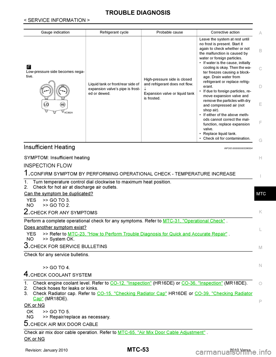
Gauge indication Refrigerant cycleProbable causeCorrective action
Low-pressure side becomes nega-
tive. Liquid tank or front/rear side of
expansion valve’s pipe is frost-
ed or dewed.High-pressure side is closed
and refrigerant does not flow.
↓
Expansion valve or liquid tank
is frosted.Leave the system at rest until
no frost is present. Start it
again to check whether or not
the malfunction is caused by
water or foreign particles.
• If water is the cause, initially
cooling is okay. Then the wa-
ter freezes causing a block-
age. Drain water from
refrigerant or replace refrig-
erant.
• If due to foreign particles, re-
move expansion valve and
remove the particles with dry
and compressed air (not
shop air).
• If either of the above meth- ods cannot correct the mal-
function, replace expansion
valve.
• Replace liquid tank.
• Check oil for contamination.
AC362A
Revision: January 20102010 Versa