2010 NISSAN TIIDA Electronic
[x] Cancel search: ElectronicPage 1384 of 3745
POWER SUPPLY AND GROUND CIRCUITEC-119
< COMPONENT DIAGNOSIS > [HR16DE]
C
D
E
F
G H
I
J
K L
M A
EC
NP
O
Refer to
EC-114, "Diagnosis Procedure".
Is the inspection result normal?
YES >> Replace IPDM E/R. Refer to PG-28, "Removal and Installation of IPDM E/R".
NO >> Repair open circuit or short to ground or short to power in harness or connectors.
Ground InspectionINFOID:0000000005398287
Ground connections are very important to the proper oper ation of electrical and electronic circuits. Ground
connections are often exposed to moisture, dirt and other corrosive elements. The corrosion (rust) can
become an unwanted resistance. This unwanted resistance can change the way a circuit works.
Electronically controlled circuits are very sensitive to proper grounding. A loose or corroded ground can drasti-
cally affect an electronically controlled circuit. A poor or corroded ground can easily affect the circuit. Even
when the ground connection looks clean, there can be a thin film of rust on the surface.
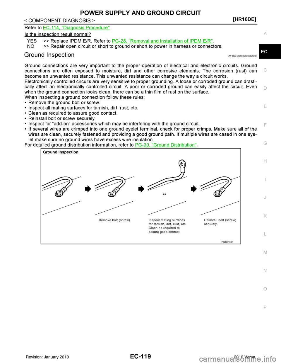
When inspecting a ground connection follow these rules:
• Remove the ground bolt or screw.
• Inspect all mating surfaces for tarnish, dirt, rust, etc.
• Clean as required to assure good contact.
• Reinstall bolt or screw securely.
• Inspect for “add-on” accessories which may be interfering with the ground circuit.
• If several wires are crimped into one ground eyelet terminal, check for proper crimps. Make sure all of the wires are clean, securely fastened and providing a good ground path. If multiple wires are cased in one eye-
let make sure no ground wires have excess wire insulation.
For detailed ground distribution information, refer to PG-30, "
Ground Distribution".
PBIB1870E
Revision: January 20102010 Versa
Page 1441 of 3745
EC-176
< COMPONENT DIAGNOSIS >[HR16DE]
P0130 A/F SENSOR 1
P0130 A/F SENSOR 1
DescriptionINFOID:0000000005398360
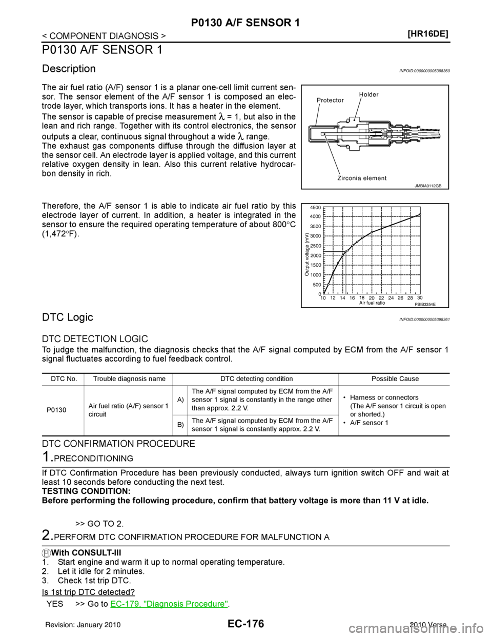
The air fuel ratio (A/F) sensor 1 is a planar one-cell limit current sen-
sor. The sensor element of the
A/F sensor 1 is composed an elec-
trode layer, which transports ions. It has a heater in the element.
The sensor is capable of precise measurement = 1, but also in the
lean and rich range. Together with its control electronics, the sensor
outputs a clear, continuous signal throughout a wide range.
The exhaust gas components diffuse through the diffusion layer at
the sensor cell. An electrode layer is applied voltage, and this current
relative oxygen density in lean. Also this current relative hydrocar-
bon density in rich.
Therefore, the A/F sensor 1 is able to indicate air fuel ratio by this
electrode layer of current. In additi on, a heater is integrated in the
sensor to ensure the required operating temperature of about 800° C
(1,472° F).
DTC LogicINFOID:0000000005398361
DTC DETECTION LOGIC
To judge the malfunction, the diagnosis checks that t he A/F signal computed by ECM from the A/F sensor 1
signal fluctuates according to fuel feedback control.
DTC CONFIRMATION PROCEDURE
1.PRECONDITIONING
If DTC Confirmation Procedure has been previously conducted, always turn ignition switch OFF and wait at
least 10 seconds before conducting the next test.
TESTING CONDITION:
Before performing the following procedure, confirm that battery voltage is more than 11 V at idle.
>> GO TO 2.
2.PERFORM DTC CONFIRMATION PROCEDURE FOR MALFUNCTION A
With CONSULT-III
1. Start engine and warm it up to normal operating temperature.
2. Let it idle for 2 minutes.
3. Check 1st trip DTC.
Is 1st trip DTC detected?
YES >> Go to EC-179, "Diagnosis Procedure".
JMBIA0112GB
PBIB3354E
DTC No. Trouble diagnosis name DTC detecting conditionPossible Cause
P0130 Air fuel ratio (A/F) sensor 1
circuit A)
The A/F signal computed by ECM from the A/F
sensor 1 signal is constantly in the range other
than approx. 2.2 V. • Harness or connectors
(The A/F sensor 1 circuit is open
or shorted.)
• A/F sensor 1
B) The A/F signal computed by ECM from the A/F
sensor 1 signal is constantly approx. 2.2 V.
Revision: January 20102010 Versa
Page 1447 of 3745
EC-182
< COMPONENT DIAGNOSIS >[HR16DE]
P0131 A/F SENSOR 1
P0131 A/F SENSOR 1
DescriptionINFOID:0000000005398365
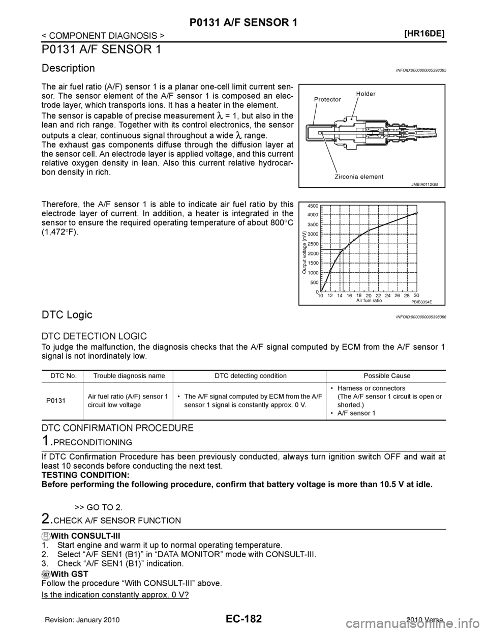
The air fuel ratio (A/F) sensor 1 is a planar one-cell limit current sen-
sor. The sensor element of the
A/F sensor 1 is composed an elec-
trode layer, which transports ions. It has a heater in the element.
The sensor is capable of precise measurement = 1, but also in the
lean and rich range. Together with its control electronics, the sensor
outputs a clear, continuous signal throughout a wide range.
The exhaust gas components diffuse through the diffusion layer at
the sensor cell. An electrode layer is applied voltage, and this current
relative oxygen density in lean. Also this current relative hydrocar-
bon density in rich.
Therefore, the A/F sensor 1 is able to indicate air fuel ratio by this
electrode layer of current. In additi on, a heater is integrated in the
sensor to ensure the required operating temperature of about 800° C
(1,472° F).
DTC LogicINFOID:0000000005398366
DTC DETECTION LOGIC
To judge the malfunction, the diagnosis checks that t he A/F signal computed by ECM from the A/F sensor 1
signal is not inordinately low.
DTC CONFIRMATION PROCEDURE
1.PRECONDITIONING
If DTC Confirmation Procedure has been previously conducted, always turn ignition switch OFF and wait at
least 10 seconds before conducting the next test.
TESTING CONDITION:
Before performing the following procedure, confirm that battery voltage is more than 10.5 V at idle.
>> GO TO 2.
2.CHECK A/F SENSOR FUNCTION
With CONSULT-III
1. Start engine and warm it up to normal operating temperature.
2. Select “A/F SEN1 (B1)” in “D ATA MONITOR” mode with CONSULT-III.
3. Check “A/F SEN1 (B1)” indication.
With GST
Follow the procedure “With CONSULT-III” above.
Is the indication constantly approx. 0 V?
JMBIA0112GB
PBIB3354E
DTC No. Trouble diagnosis name DTC detecting conditionPossible Cause
P0131 Air fuel ratio (A/F) sensor 1
circuit low voltage • The A/F signal computed by ECM from the A/F
sensor 1 signal is constantly approx. 0 V. • Harness or connectors
(The A/F sensor 1 circuit is open or
shorted.)
• A/F sensor 1
Revision: January 20102010 Versa
Page 1452 of 3745
P0132 A/F SENSOR 1EC-187
< COMPONENT DIAGNOSIS > [HR16DE]
C
D
E
F
G H
I
J
K L
M A
EC
NP
O
P0132 A/F SENSOR 1
DescriptionINFOID:0000000005398369
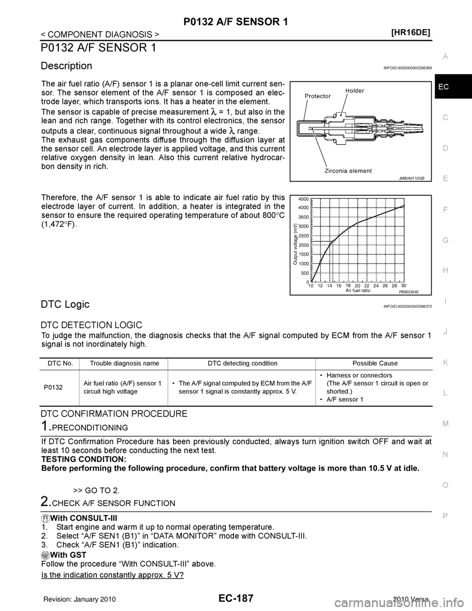
The air fuel ratio (A/F) sensor 1 is a planar one-cell limit current sen-
sor. The sensor element of the A/F sensor 1 is composed an elec-
trode layer, which transports ions. It has a heater in the element.
The sensor is capable of precise m
easurement = 1, but also in the
lean and rich range. Together with its control electronics, the sensor
outputs a clear, continuous signal throughout a wide range.
The exhaust gas components diffuse through the diffusion layer at
the sensor cell. An electrode layer is applied voltage, and this current
relative oxygen density in lean. Also this current relative hydrocar-
bon density in rich.
Therefore, the A/F sensor 1 is able to indicate air fuel ratio by this
electrode layer of current. In addition, a heater is integrated in the
sensor to ensure the required operating temperature of about 800 °C
(1,472 °F).
DTC LogicINFOID:0000000005398370
DTC DETECTION LOGIC
To judge the malfunction, the diagnosis checks that the A/F signal computed by ECM from the A/F sensor 1
signal is not inordinately high.
DTC CONFIRMATION PROCEDURE
1.PRECONDITIONING
If DTC Confirmation Procedure has been previously conducted, always turn ignition switch OFF and wait at
least 10 seconds before conducting the next test.
TESTING CONDITION:
Before performing the following procedure, confirm that battery voltage is more than 10.5 V at idle.
>> GO TO 2.
2.CHECK A/F SENSOR FUNCTION
With CONSULT-III
1. Start engine and warm it up to normal operating temperature.
2. Select “A/F SEN1 (B1)” in “DAT A MONITOR” mode with CONSULT-III.
3. Check “A/F SEN1 (B1)” indication.
With GST
Follow the procedure “With CONSULT-III” above.
Is the indication constantly approx. 5 V?
JMBIA0112GB
PBIB3354E
DTC No. Trouble diagnosis name DTC detecting conditionPossible Cause
P0132 Air fuel ratio (A/F) sensor 1
circuit high voltage • The A/F signal computed by ECM from the A/F
sensor 1 signal is constantly approx. 5 V. • Harness or connectors
(The A/F sensor 1 circuit is open or
shorted.)
• A/F sensor 1
Revision: January 20102010 Versa
Page 1457 of 3745
EC-192
< COMPONENT DIAGNOSIS >[HR16DE]
P0133 A/F SENSOR 1
P0133 A/F SENSOR 1
DescriptionINFOID:0000000005398373
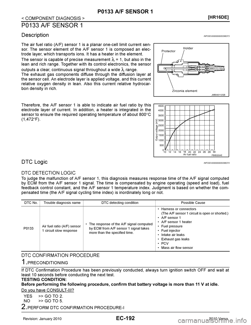
The air fuel ratio (A/F) sensor 1 is a planar one-cell limit current sen-
sor. The sensor element of the
A/F sensor 1 is composed an elec-
trode layer, which transports ions. It has a heater in the element.
The sensor is capable of precise measurement = 1, but also in the
lean and rich range. Together with its control electronics, the sensor
outputs a clear, continuous signal throughout a wide range.
The exhaust gas components diffuse through the diffusion layer at
the sensor cell. An electrode layer is applied voltage, and this current
relative oxygen density in lean. Also this current relative hydrocar-
bon density in rich.
Therefore, the A/F sensor 1 is able to indicate air fuel ratio by this
electrode layer of current. In additi on, a heater is integrated in the
sensor to ensure the required operating temperature of about 800° C
(1,472° F).
DTC LogicINFOID:0000000005398374
DTC DETECTION LOGIC
To judge the malfunction of A/F sensor 1, this diagnosis measures response time of the A/F signal computed
by ECM from the A/F sensor 1 signal. The time is compensated by engine operating (speed and load), fuel
feedback control constant, and the A/F sensor 1 temper ature index. Judgment is based on whether the com-
pensated time (the A/F signal cycling time index) is inordinately long or not.
DTC CONFIRMATION PROCEDURE
1.PRECONDITIONING
If DTC Confirmation Procedure has been previously conducted, always turn ignition switch OFF and wait at
least 10 seconds before conducting the next test.
TESTING CONDITION:
Before performing the following procedure, confirm that battery voltage is more than 11 V at idle.
Do you have CONSULT-III?
YES >> GO TO 2.
NO >> GO TO 5.
2.PERFORM DTC CONFIRMATION PROCEDURE-I
JMBIA0112GB
PBIB3354E
DTC No. Trouble diagnosis name DTC detecting condition Possible Cause
P0133 Air fuel ratio (A/F) sensor
1 circuit slow response • The response of the A/F signal computed
by ECM from A/F sensor 1 signal takes
more than the specified time. • Harness or connectors
(The A/F sensor 1 circuit is open or shorted.)
• A/F sensor 1
• A/F sensor 1 heater
• Fuel pressure
• Fuel injector
• Intake air leaks
• Exhaust gas leaks
•PCV
• Mass air flow sensor
Revision: January 20102010 Versa
Page 1675 of 3745
EC-410
< COMPONENT DIAGNOSIS >[HR16DE]
P2A00 A/F SENSOR 1
P2A00 A/F SENSOR 1
DescriptionINFOID:0000000005398592
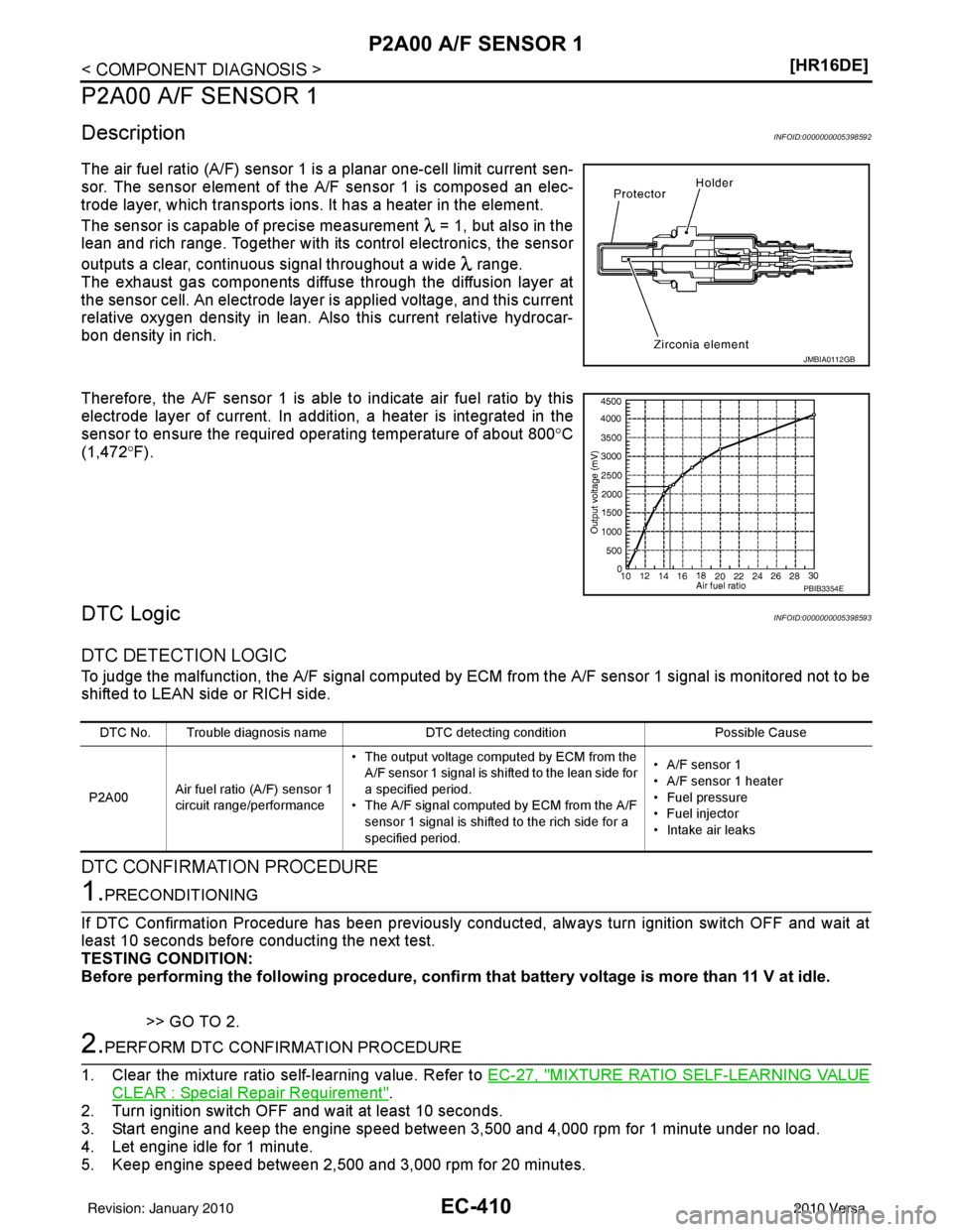
The air fuel ratio (A/F) sensor 1 is a planar one-cell limit current sen-
sor. The sensor element of the
A/F sensor 1 is composed an elec-
trode layer, which transports ions. It has a heater in the element.
The sensor is capable of precise measurement = 1, but also in the
lean and rich range. Together with its control electronics, the sensor
outputs a clear, continuous signal throughout a wide range.
The exhaust gas components diffuse through the diffusion layer at
the sensor cell. An electrode layer is applied voltage, and this current
relative oxygen density in lean. Also this current relative hydrocar-
bon density in rich.
Therefore, the A/F sensor 1 is able to indicate air fuel ratio by this
electrode layer of current. In additi on, a heater is integrated in the
sensor to ensure the required operating temperature of about 800° C
(1,472° F).
DTC LogicINFOID:0000000005398593
DTC DETECTION LOGIC
To judge the malfunction, the A/F signal computed by ECM from the A/F sensor 1 signal is monitored not to be
shifted to LEAN side or RICH side.
DTC CONFIRMATION PROCEDURE
1.PRECONDITIONING
If DTC Confirmation Procedure has been previously conducted, always turn ignition switch OFF and wait at
least 10 seconds before conducting the next test.
TESTING CONDITION:
Before performing the following procedure, confirm that battery voltage is more than 11 V at idle.
>> GO TO 2.
2.PERFORM DTC CONFIRMATION PROCEDURE
1. Clear the mixture ratio self-learning value. Refer to EC-27, "
MIXTURE RATIO SELF-LEARNING VALUE
CLEAR : Special Repair Requirement".
2. Turn ignition switch OFF and wait at least 10 seconds.
3. Start engine and keep the engine speed between 3,500 and 4,000 rpm for 1 minute under no load.
4. Let engine idle for 1 minute.
5. Keep engine speed between 2,500 and 3,000 rpm for 20 minutes.
JMBIA0112GB
PBIB3354E
DTC No. Trouble diagnosis name DTC detecting conditionPossible Cause
P2A00 Air fuel ratio (A/F) sensor 1
circuit range/performance • The output voltage computed by ECM from the
A/F sensor 1 signal is shifted to the lean side for
a specified period.
• The A/F signal computed by ECM from the A/F sensor 1 signal is shifted to the rich side for a
specified period. • A/F sensor 1
• A/F sensor 1 heater
• Fuel pressure
• Fuel injector
• Intake air leaks
Revision: January 20102010 Versa
Page 1758 of 3745
PRECAUTIONSEC-493
< PRECAUTION > [HR16DE]
C
D
E
F
G H
I
J
K L
M A
EC
NP
O
•
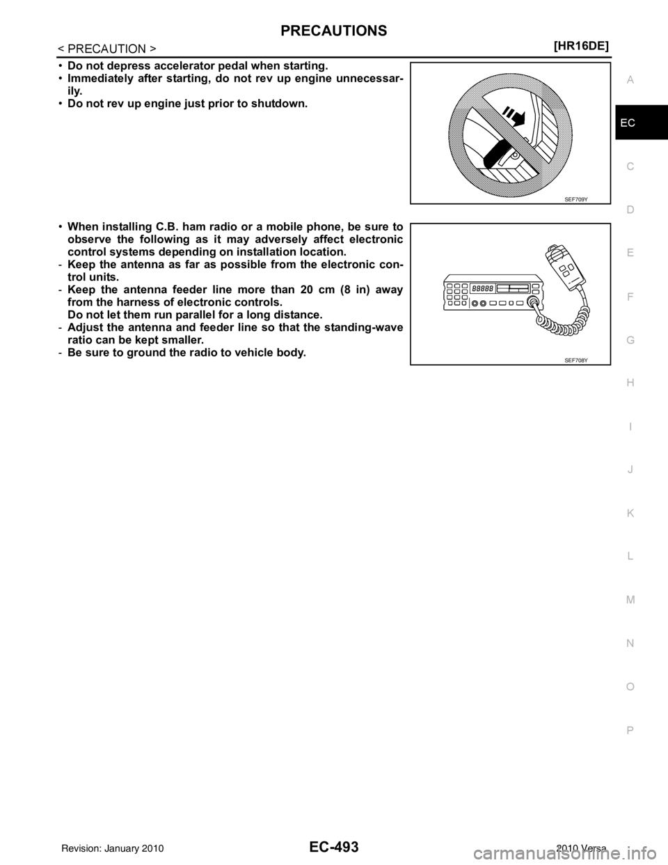
Do not depress accelerator pedal when starting.
• Immediately after starting, do not rev up engine unnecessar-
ily.
• Do not rev up engine ju st prior to shutdown.
• When installing C.B. ham radio or a mobile phone, be sure to
observe the following as it may adversely affect electronic
control systems depending on installation location.
- Keep the antenna as far as possible from the electronic con-
trol units.
- Keep the antenna feeder line more than 20 cm (8 in) away
from the harness of electronic controls.
Do not let them run para llel for a long distance.
- Adjust the antenna and feeder line so that the standing-wave
ratio can be kept smaller.
- Be sure to ground the radio to vehicle body.
SEF709Y
SEF708Y
Revision: January 20102010 Versa
Page 1778 of 3745
PRECAUTIONSEC-513
< SERVICE INFORMATION > [MR18DE]
C
D
E
F
G H
I
J
K L
M A
EC
NP
O
•
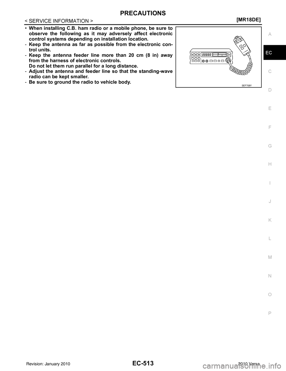
When installing C.B. ham radio or a mobile phone, be sure to
observe the following as it may adversely affect electronic
control systems depending on installation location.
- Keep the antenna as far as possible from the electronic con-
trol units.
- Keep the antenna feeder line more than 20 cm (8 in) away
from the harness of electronic controls.
Do not let them run para llel for a long distance.
- Adjust the antenna and feeder line so that the standing-wave
radio can be kept smaller.
- Be sure to ground the radio to vehicle body.
SEF708Y
Revision: January 20102010 Versa