2010 NISSAN TIIDA stop start
[x] Cancel search: stop startPage 129 of 3745

AT-112
< SERVICE INFORMATION >
P0732 2GR INCORRECT RATIO
P0732 2GR INCORRECT RATIO
DescriptionINFOID:0000000005397294
• This malfunction will not be detected while the OD OFF indicator lamp is indicating another self-diagnosismalfunction.
• This malfunction is detected when the A/T does not shif t into second gear position as instructed by the TCM.
This is not caused by electrical malfunction (circuit s open or shorted) but by mechanical malfunction such as
control valve sticking, improper solenoid valve operation, etc.
On Board Diagn osis LogicINFOID:0000000005397295
• This is an OBD-II self-diagnostic item.
• Diagnostic trouble code “P0732 2GR INCORRECT RATIO” with CONSULT-III is detected when A/T cannot
be shifted to the 2GR position even if electrical circuit is good.
• This diagnosis monitors actual gear position by checki ng the torque converter slip ratio calculated by TCM
as follows:
Torque converter slip ratio = A x C/B
A: Output shaft revolution signal from output speed sensor
B: Engine speed signal from ECM
C: Gear ratio determined as gear position which TCM supposes
If the actual gear position is higher than the position (2nd) supposed by TCM, the slip ratio will be more than
normal. In case the ratio exceeds the specif ied value, TCM judges this diagnosis malfunction.
This malfunction will be caused when shift solenoid valve B is stuck open.
• Gear positions supposed by TCM are as follows: In case of gear position with no malfunctions: 1, 2 , 3 and 4 positions
In case of gear position with shift solenoid valve B stuck open: 4, 3*, 3 and 4 positions to each gear position
above
*: “P0732 2GR INCORRECT RATIO” is detected.
Possible CauseINFOID:0000000005397296
• Shift solenoid valve B
• Each clutch
• Hydraulic control circuit
DTC Confirmation ProcedureINFOID:0000000005397297
CAUTION:
• Always drive vehicle at a safe speed.
• If performing this “DTC Confirmation Procedure” again, always turn ignition switch OFF and wait at
least 10 seconds before continuing.
After the repair, perform the following proc edure to confirm the malfunction is eliminated.
WITH CONSULT-III
1. Start engine and select “DATA MONITOR” m ode for “TRANSMISSION” with CONSULT-III.
2. Touch “START”.
3. Make sure that output voltage of A/T fluid temperature sensor is within the range below.
FLUID TEMP SE: 0.4 - 1.5 V
If out of range, drive the vehicle to decrease the vo ltage (warm up the fluid) or stop engine to increase the
voltage (cool down the fluid).
4. Select “2ND GR FNCTN P0732” of “DTC & SR T CONFIRMATION” mode for “TRANSMISSION” with
CONSULT-III and touch “START”.
5. Accelerate vehicle to 45 to 50 km/h (28 to 31 MPH) under the following conditions and release the accel- erator pedal completely.
THROTTLE POSI: Less than 1.0/8
SLCT LVR POSI: “D” position
Gear position 12 34
Shift solenoid valve A ON (Closed)OFF (Open)OFF (Open)ON (Closed)
Shift solenoid valve B ON (Closed)ON (Closed) OFF (Open)OFF (Open)
Revision: January 20102010 Versa
Page 132 of 3745

P0733 3GR INCORRECT RATIOAT-115
< SERVICE INFORMATION >
DE
F
G H
I
J
K L
M A
B
AT
N
O P
P0733 3GR INCORRECT RATIO
DescriptionINFOID:0000000005397299
• This malfunction will not be detected while the OD OFF indicator lamp is indicating another self-diagnosis malfunction.
• This malfunction is detected when the A/T does not shif t into third gear position as instructed by the TCM.
This is not caused by electrical malfunction (circuit s open or shorted) but by mechanical malfunction such as
control valve sticking, improper solenoid valve operat ion, malfunctioning servo piston or brake band, etc.
On Board Diagnosis LogicINFOID:0000000005397300
• This is an OBD-II self-diagnostic item.
• Diagnostic trouble code “P0733 3GR INCORRECT RATIO” with CONSULT-III is detected when A/T cannot
be shifted to the 3GR position even if electrical circuit is good.
• This diagnosis monitors actual gear position by checki ng the torque converter slip ratio calculated by TCM
as follows:
Torque converter slip ratio = A x C/B
A: Output shaft revolution signal from output speed sensor
B: Engine speed signal from ECM
C: Gear ratio determined as gear position which TCM supposes
If the actual gear position is higher than the position (3rd) supposed by TCM, the slip ratio will be more than
normal. In case the ratio exceeds the specif ied value, TCM judges this diagnosis malfunction.
This malfunction will be caused when shift solenoid valve A is stuck closed.
• Gear positions supposed by TCM are as follows. In case of gear position with no malfunctions: 1, 2, 3 and 4 positions
In case of gear position with shift solenoid valve A stuck closed: 1, 1, 4* and 4 positions to each gear position
above
*: “P0733 3GR INCORRECT RATIO” is detected.
Possible CauseINFOID:0000000005397301
• Shift solenoid valve A
• Each clutch
• Hydraulic control circuit
DTC Confirmation ProcedureINFOID:0000000005397302
CAUTION:
• Always drive vehicle at a safe speed.
• If performing this “DTC Confirmation Procedure” again, always turn ignition switch OFF and wait at
least 10 seconds before continuing.
After the repair, perform the following procedure to confirm the malfunction is eliminated.
WITH CONSULT-III
1. Start engine and select “DATA MONITOR” m ode for “TRANSMISSION” with CONSULT-III.
2. Touch “START”.
3. Make sure that output voltage of A/T fluid temperature sensor is within the range below. FLUID TEMP SE: 0.4 - 1.5 V
If out of range, drive the vehicle to decrease the vo ltage (warm up the fluid) or stop engine to increase the
voltage (cool down the fluid).
4. Select “3RD GR FNCTN P0733” of “DTC & SR T CONFIRMATION” mode for “TRANSMISSION” with
CONSULT-III and touch “START”.
5. Accelerate vehicle to 60 to 75 km/h (37 to 47 MPH) under the following conditions and release the accel- erator pedal completely.
THROTTLE POSI: Less th an 1.0/8 (at all times during step 4)
SLCT LVR POSI: “D” position
Gear position 123 4
Shift solenoid valve A ON (Closed)OFF (Open)OFF (Open)ON (Closed)
Shift solenoid valve B ON (Closed)ON (Closed) OFF (Open)OFF (Open)
Revision: January 20102010 Versa
Page 136 of 3745

P0734 4GR INCORRECT RATIOAT-119
< SERVICE INFORMATION >
DE
F
G H
I
J
K L
M A
B
AT
N
O P
WITH CONSULT-III
1. Start engine and select “DATA MONITOR” m ode for “TRANSMISSION” with CONSULT-III.
2. Touch “START”.
3. Make sure that output voltage of A/T fluid temperature sensor is within the range below. FLUID TEMP SE: 0.4 - 1.5 V
If out of range, drive the vehicle to decrease the vo ltage (warm up the fluid) or stop engine to increase the
voltage (cool down the fluid).
4. Select “4TH GR FNCTN P0734” of “DTC & SR T CONFIRMATION” mode for “TRANSMISSION” with
CONSULT-III and touch “START”.
5. Accelerate vehicle to 55 to 65 km/h (34 to 40 MPH) under the following conditions and release the accel-
erator pedal completely.
THROTTLE POSI: Less th an 5.5/8 (at all times during step 4)
SLCT LVR POSI: “D” position
- Make sure that “GEAR” shows “3” after releasing pedal.
6. Depress accelerator pedal steadily with 1.0/8 - 2.0/ 8 of “THROTTLE POSI” from a speed of 55 to 65 km/h
(34 to 40 MPH) until “TESTING” has turned to “STO P VEHICLE” or “COMPLETED”. (It will take approxi-
mately 3 seconds.)
If the check result NG appears on CONSULT-III screen, go to AT-119, "
Diagnosis Procedure".
If “STOP VEHICLE” appears on CONSULT-III screen, go to following step.
- Make sure that “GEAR” shows “4” when depressing accelerator pedal with 1.0/8 - 2.0/8 of
“THROTTLE POSI”.
- If “TESTING” does not appear on CONSULT-III fo r a long time, select “SELF-DIAG RESULTS” for
“TRANSMISSION”. In case a DTC other than “P0734 4GR INCORRECT RATIO” is shown, refer to
AT-77, "
CONSULT-III Function (TRANSMISSION)".
7. Stop vehicle.
8. Follow the instruction displayed. (Check for normal shifting referring to the table below.)
9. Make sure that “OK” is disp layed. (If “NG” is displayed, refer to “Diagnostic Procedure”.)
Refer to AT-119, "
Diagnosis Procedure".
Refer to AT-64, "
Vehicle Speed at Which Gear Shifting Occurs".
WITH GST
Follow the procedure “WITH CONSULT-III”.
Diagnosis ProcedureINFOID:0000000005397309
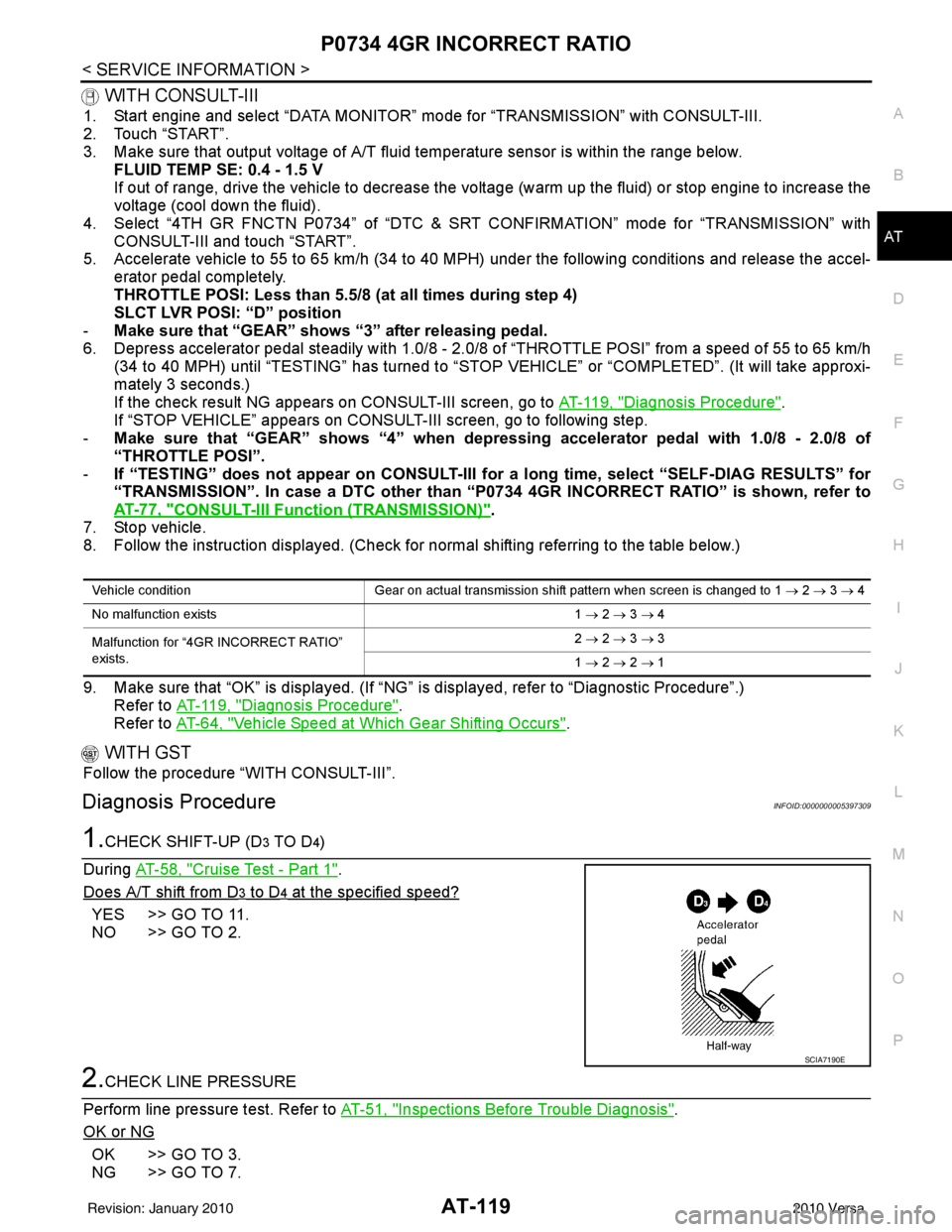
1.CHECK SHIFT-UP (D3 TO D4)
During AT-58, "
Cruise Test - Part 1".
Does A/T shift from D
3 to D4 at the specified speed?
YES >> GO TO 11.
NO >> GO TO 2.
2.CHECK LINE PRESSURE
Perform line pressure test. Refer to AT-51, "
Inspections Before Trouble Diagnosis".
OK or NG
OK >> GO TO 3.
NG >> GO TO 7.
Vehicle condition Gear on actual transmission shift pattern when screen is changed to 1 → 2 → 3 → 4
No malfunction exists 1 → 2 → 3 → 4
Malfunction for “4GR INCORRECT RATIO”
exists. 2
→ 2 → 3 → 3
1 → 2 → 2 → 1
SCIA7190E
Revision: January 20102010 Versa
Page 145 of 3745

AT-128
< SERVICE INFORMATION >
P0744 TORQUE CONVERTER
P0744 TORQUE CONVERTER
DescriptionINFOID:0000000005397318
• This malfunction will not be detected while the OD OFF indicator lamp is indicating another self-diagnosismalfunction.
• This malfunction is detected when the A/T does not shif t into fourth gear position or the torque converter
clutch does not lock-up as instructed by the TCM. This is not caused by electrical malfunction (circuits open
or shorted) but by mechanical malfunction such as c ontrol valve sticking, improper solenoid valve operation,
malfunctioning oil pump or torque converter clutch, etc.
CONSULT-III Reference Value in Data Monitor ModeINFOID:0000000005397319
Remarks: Specification data are reference values.
On Board Diagn osis LogicINFOID:0000000005397320
• This is an OBD-II self-diagnostic item.
• Diagnostic trouble code “P0744 T/C CLUTCH FNCTN” wit h CONSULT-III is detected when A/T cannot per-
form lock-up even if electrical circuit is good.
• This diagnosis monitors actual gear position by checki ng the torque converter slip ratio calculated by TCM
as follows:
Torque converter slip ratio = A x C/B
A: Output shaft revolution signal from output speed sensor
B: Engine speed signal from ECM
C: Gear ratio determined as gear position which TCM supposes
If the actual gear position is much lower than the pos ition (4th) supposed by TCM, the slip ratio will be much
less than normal. In case the ratio does not reach t he specified value, TCM judges this diagnosis malfunc-
tion.
This malfunction will be caused when shift solenoid valve B is stuck closed.
• Gear positions supposed by TCM are as follows.
In case of gear position with no malfunctions: 1, 2, 3 and 4 positions
In case of gear position with shift solenoid valve B stuc k closed: 1, 2, 2 and 1* positions to each gear position
above
*: “P0744 T/C CLUTCH FNCTN” is detected.
Possible CauseINFOID:0000000005397321
• Line pressure solenoid valve
• Torque converter clutch solenoid valve
• Each clutch
• Hydraulic control circuit
DTC Confirmation ProcedureINFOID:0000000005397322
CAUTION:
• Always drive vehicle at a safe speed.
• If performing this “DTC Confirmation Procedure” again, always turn ignition switch OFF and wait at
least 10 seconds before continuing.
After the repair, perform the following proc edure to confirm the malfunction is eliminated.
WITH CONSULT-III
1. Start engine and select “DATA MONITOR” m ode for “TRANSMISSION” with CONSULT-III.
2. Touch “START”.
3. Make sure that output voltage of A/T fluid temperature sensor is within the range below.
FLUID TEMP SE: 0.4 - 1.5 V
If out of range, drive vehicle to decrease voltage (warm up the fluid) or stop engine to increase voltage
(cool down the fluid).
4. Select “TCC S/V FNCTN P0744” of “DTC & SR T CONFIRMATION” mode for “TRANSMISSION” with
CONSULT-III and touch “START”.
Item name Condition Display value (Approx)
TCC S/V DUTY Lock-up OFF ⇔ Lock-up ON 4% ⇔ 94%
Revision: January 20102010 Versa
Page 234 of 3745

SHIFT CONTROL SYSTEMAT-217
< SERVICE INFORMATION >
DE
F
G H
I
J
K L
M A
B
AT
N
O P
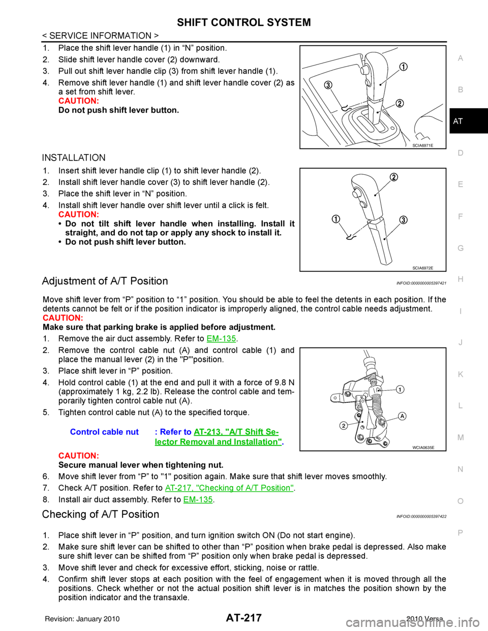
1. Place the shift lever handle (1) in “N” position.
2. Slide shift lever handle cover (2) downward.
3. Pull out shift lever handle clip (3) from shift lever handle (1).
4. Remove shift lever handle (1) and shift lever handle cover (2) as a set from shift lever.
CAUTION:
Do not push shift lever button.
INSTALLATION
1. Insert shift lever handle clip (1) to shift lever handle (2).
2. Install shift lever handle cover (3) to shift lever handle (2).
3. Place the shift lever in “N” position.
4. Install shift lever handle over shift lever until a click is felt.CAUTION:
• Do not tilt shift lever handle when installing. Install it
straight, and do not tap or ap ply any shock to install it.
• Do not push shift lever button.
Adjustment of A/T PositionINFOID:0000000005397421
Move shift lever from “P” position to “1” position. You should be able to feel the detents in each position. If the
detents cannot be felt or if the position indicator is improperly aligned, the control cable needs adjustment.
CAUTION:
Make sure that parking brake is applied before adjustment.
1. Remove the air duct assembly. Refer to EM-135
.
2. Remove the control cable nut (A) and control cable (1) and place the manual lever (2) in the "P'"position.
3. Place shift lever in “P” position.
4. Hold control cable (1) at the end and pull it with a force of 9.8 N (approximately 1 kg, 2.2 lb). Release the control cable and tem-
porarily tighten control cable nut (A).
5. Tighten control cable nut (A) to the specified torque.
CAUTION:
Secure manual lever when tightening nut.
6. Move shift lever from “P” to "1" position again. Make sure that shift lever moves smoothly.
7. Check A/T position. Refer to AT-217, "
Checking of A/T Position".
8. Install air duct assembly. Refer to EM-135
.
Checking of A/T PositionINFOID:0000000005397422
1. Place shift lever in “P” position, and turn ignition switch ON (Do not start engine).
2. Make sure shift lever can be shifted to other t han “P” position when brake pedal is depressed. Also make
sure shift lever can be shifted from “P” position only when brake pedal is depressed.
3. Move shift lever and check for excessive effort, sticking, noise or rattle.
4. Confirm shift lever stops at each position with the feel of engagement when it is moved through all the positions. Check whether or not the actual position shift lever is in matches the position shown by the
position indicator and the transaxle.
SCIA6971E
SCIA6972E
Control cable nut : Refer to AT-213, "A/T Shift Se-
lector Removal and Installation".WCIA0635E
Revision: January 20102010 Versa
Page 518 of 3745

SQUEAK AND RATTLE TROUBLE DIAGNOSESBL-9
< SERVICE INFORMATION >
C
DE
F
G H
J
K L
M A
B
BL
N
O P
SILICONE GREASE
Used instead of UHMW tape that will be visible or not fit.
Note: Will only last a few months.
SILICONE SPRAY
Use when grease cannot be applied.
DUCT TAPE
Use to eliminate movement.
CONFIRM THE REPAIR
Confirm that the cause of a noise is repaired by test driving the vehicle. Operate the vehicle under the same
conditions as when the noise originally occurred. Refer to the notes on the Diagnostic Worksheet.
Generic Squeak and Rattle TroubleshootingINFOID:0000000005396545
Refer to Table of Contents for specific component removal and installation information.
INSTRUMENT PANEL
Most incidents are caused by contact and movement between:
1. The cluster lid A and instrument panel
2. Acrylic lens and combination meter housing
3. Instrument panel to front pillar garnish
4. Instrument panel to windshield
5. Instrument panel mounting pins
6. Wiring harnesses behind the combination meter
7. A/C defroster duct and duct joint
These incidents can usually be located by tapping or moving the components to duplicate the noise or by
pressing on the components while driving to stop the noi se. Most of these incidents can be repaired by apply-
ing felt cloth tape or silicone spray (in hard to reach areas). Urethane pads can be used to insulate wiring har-
ness.
CAUTION:
Do not use silicone spray to isolate a squeak or ra ttle. If you saturate the area with silicone, you will
not be able to recheck the repair.
CENTER CONSOLE
Components to pay attention to include:
1. Shifter assembly cover to finisher
2. A/C control unit and cluster lid C
3. Wiring harnesses behind audio and A/C control unit
The instrument panel repair and isolation pr ocedures also apply to the center console.
DOORS
Pay attention to the:
1. Finisher and inner panel making a slapping noise
2. Inside handle escutcheon to door finisher
3. Wiring harnesses tapping
4. Door striker out of alignment causing a popping noise on starts and stops
Tapping or moving the components or pressing on them while driving to duplicate the conditions can isolate
many of these incidents. You can usually insulate the ar eas with felt cloth tape or insulator foam blocks from
the NISSAN Squeak and Rattle Kit (J-43980) to repair the noise.
TRUNK
Trunk noises are often caused by a loose jack or loose items put into the trunk by the owner.
In addition look for:
1. Trunk lid bumpers out of adjustment
2. Trunk lid striker out of adjustment
3. The trunk lid torsion bars knocking together
4. A loose license plate or bracket
Revision: January 20102010 Versa
Page 630 of 3745

INTELLIGENT KEY SYSTEMBL-121
< SERVICE INFORMATION >
C
DE
F
G H
J
K L
M A
B
BL
N
O P
• Make sure that vehicle is under the condition shown in “Conditions of vehicle” before starting diagnosis, and
check each symptom.
• If the following “symptoms” are detected, check syst ems shown in the “Diagnoses/service procedure” col-
umn in this order.
Conditions of Vehicle (Operating Conditions)
• Intelligent Key is registered.
• Multiple mechanical keys are not set in a keyfob. (If mechanical keys are near the ignition switch, the operation may not work properly.)
ENGINE START CONDITION CHECK
NOTE:
• Before performing the diagnosis in the following table, check “Trouble Diagnosis Procedure”. Refer to BL-
115, "Trouble Diagnosis Procedure".
• If the following “symptoms” are detected, check syst ems shown in the ”Diagnoses/service procedure” col-
umn in this order.
ALL FUNCTIONS OF INTELLIGENT KEY SYSTEM DO NOT OPERATE
NOTE:
• Before performing the diagnosis in the following table, check “Trouble Diagnosis Procedure”. Refer to BL-
115, "Trouble Diagnosis Procedure".
• Make sure that vehicle is under the condition shown in “Conditions of vehicle” before starting diagnosis, and
check each symptom.
• If the following “symptoms” are detected, check syst ems shown in the “Diagnosis/service procedure” column
in this order.
Conditions of Vehicle (Operating Conditions)
• “ENGINE START BY I-KEY” and “LOCK/UNLOCK BY I-KEY” are ON when setting on CONSULT-III.
• Mechanical key is out of ignition switch.
• Ignition switch is not depressed.
• All doors are closed.
• Intelligent key is registered.
DOOR LOCK/UNLOCK FUNCTION MALFUNCTION
NOTE:
• Before performing the diagnosis in the following table, check “Trouble Diagnosis Procedure”. Refer to BL-
115, "Trouble Diagnosis Procedure".
• Make sure that vehicle is under the condition shown in “Conditions of vehicle” before starting diagnosis, and
check each symptom.
Symptom Diagnosis/service procedure Reference page
Non DTC Item 1. Check key switch.
BL-127
2. Check NATS antenna amp.BL-248
SymptomDiagnosis/service procedure Reference page
Engine start condition check 1. Check CVT or A/T shift selector (park position switch).
(with CVT or A/T) BL-153
2. Check key interlock solenoid (with M/T).
BL-149
3. Check stop lamp switch (with CVT or A/T).BL-150
4. Check stop lamp switch (with M/T).BL-152
SymptomDiagnosis/service procedureReference page
All function of Intelligent Key system dose not
operate. 1. Check Intelligent Key unit power supply and ground
circuit. BL-126
2. Check Intelligent Key battery inspection.
BL-158
3. Replace Intelligent Key unit.BL-158
Revision: January 20102010 Versa
Page 855 of 3745

BRAKE PEDALBR-7
< SERVICE INFORMATION >
C
DE
G H
I
J
K L
M A
B
BR
N
O P
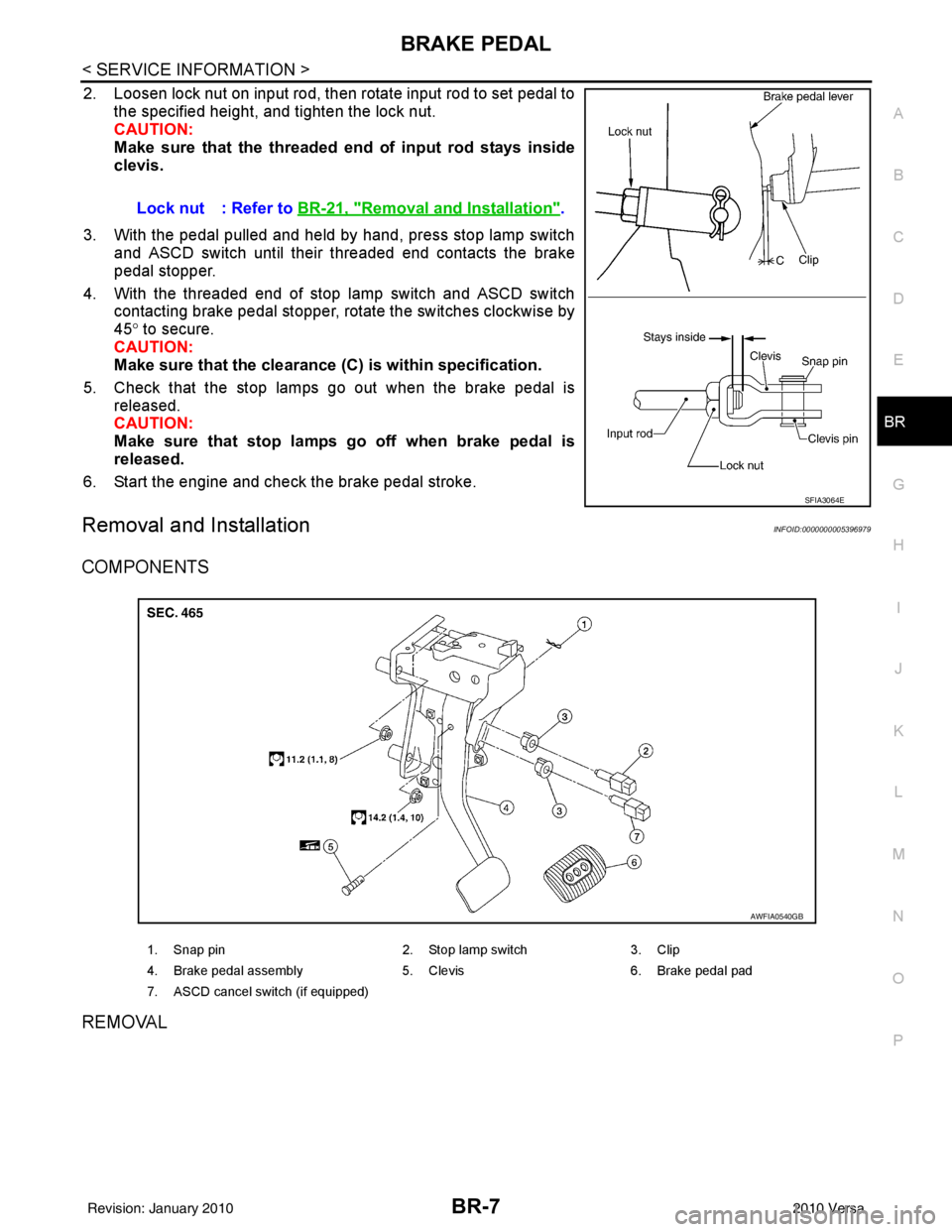
2. Loosen lock nut on input rod, then rotate input rod to set pedal to the specified height, and tighten the lock nut.
CAUTION:
Make sure that the threaded end of input rod stays inside
clevis.
3. With the pedal pulled and held by hand, press stop lamp switch and ASCD switch until their threaded end contacts the brake
pedal stopper.
4. With the threaded end of stop lamp switch and ASCD switch contacting brake pedal stopper, rotate the switches clockwise by
45° to secure.
CAUTION:
Make sure that the clearance (C) is within specification.
5. Check that the stop lamps go out when the brake pedal is released.
CAUTION:
Make sure that stop lamps go off when brake pedal is
released.
6. Start the engine and check the brake pedal stroke.
Removal and InstallationINFOID:0000000005396979
COMPONENTS
REMOVAL
Lock nut : Refer to BR-21, "Removal and Installation".
SFIA3064E
1. Snap pin 2. Stop lamp switch3. Clip
4. Brake pedal assembly 5. Clevis6. Brake pedal pad
7. ASCD cancel switch (if equipped)
AWFIA0540GB
Revision: January 20102010 Versa