2010 NISSAN TIIDA manual transmission
[x] Cancel search: manual transmissionPage 242 of 3745
ON-VEHICLE SERVICEAT-225
< SERVICE INFORMATION >
DE
F
G H
I
J
K L
M A
B
AT
N
O P
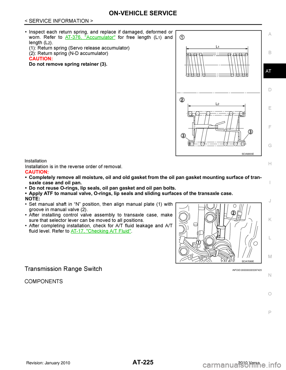
• Inspect each return spring, and replace if damaged, deformed or worn. Refer to AT-376, "
Accumulator" for free length (L1) and
length (L
2).
(1): Return spring (Servo release accumulator)
(2): Return spring (N-D accumulator)
CAUTION:
Do not remove spring retainer (3).
Installation
Installation is in the reverse order of removal.
CAUTION:
• Completely remove all moisture, oil and old gasket from the oil pan gasket mounting surface of tran-
saxle case and oil pan.
• Do not reuse O-rings, lip seals, oil pan gasket and oil pan bolts.
• Apply ATF to manual valve, O-rings, lip seals and sliding surfaces of the transaxle case.
NOTE:
• Set manual shaft in “N” position, then align manual plate (1) with groove in manual valve (2).
• After installing control valve assembly to transaxle case, make sure that selector lever can be moved to all positions.
• After completing installation, check for A/T fluid leakage and A/T fluid level. Refer to AT-17, "
Checking A/T Fluid".
Transmission Range SwitchINFOID:0000000005397425
COMPONENTS
SCIA6955E
SCIA7090E
Revision: January 20102010 Versa
Page 243 of 3745
AT-226
< SERVICE INFORMATION >
ON-VEHICLE SERVICE
REMOVAL AND INSTALLATION
Removal
1. Disconnect the battery negative terminal.
2. Remove air duct (inlet). Refer to EM-135
.
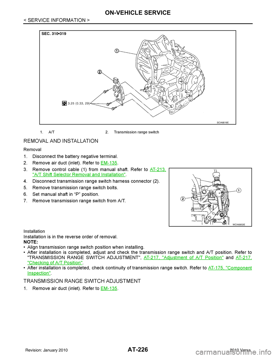
3. Remove control cable (1) from manual shaft. Refer to AT-213,
"A/T Shift Selector Removal and Installation".
4. Disconnect transmission range switch harness connector (2).
5. Remove transmission range switch bolts.
6. Set manual shaft in “P” position.
7. Remove transmission range switch from A/T.
Installation
Installation is in the reverse order of removal.
NOTE:
• Align transmission range switch position when installing.
• After installation is completed, adjust and check the transmission range switch and A/T position. Refer to
"TRANSMISSION RANGE SWITCH ADJUSTMENT", AT-217, "
Adjustment of A/T Position" and AT-217,
"Checking of A/T Position".
• After installation is completed, check cont inuity of transmission range switch. Refer to AT-175, "
Component
Inspection".
TRANSMISSION RANGE SWITCH ADJUSTMENT
1. Remove air duct (inlet). Refer to EM-135.
1. A/T 2. Transmission range switch
SCIA8018E
WCIA0653E
Revision: January 20102010 Versa
Page 244 of 3745
ON-VEHICLE SERVICEAT-227
< SERVICE INFORMATION >
DE
F
G H
I
J
K L
M A
B
AT
N
O P
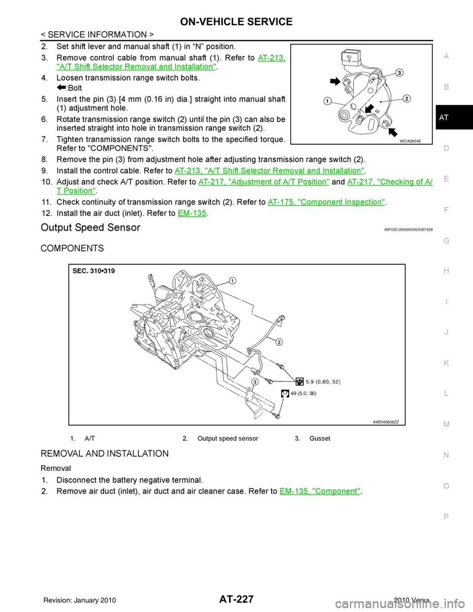
2. Set shift lever and manual shaft (1) in “N” position.
3. Remove control cable from manual shaft (1). Refer to AT-213,
"A/T Shift Selector Removal and Installation".
4. Loosen transmission range switch bolts. :Bolt
5. Insert the pin (3) [4 mm (0.16 in) dia.] straight into manual shaft (1) adjustment hole.
6. Rotate transmission range switch (2) until the pin (3) can also be inserted straight into hole in transmission range switch (2).
7. Tighten transmission range switch bolts to the specified torque. Refer to "COMPONENTS".
8. Remove the pin (3) from adjustment hole after adjusting transmission range switch (2).
9. Install the control cable. Refer to AT-213, "
A/T Shift Selector Removal and Installation".
10. Adjust and check A/T position. Refer to AT-217, "
Adjustment of A/T Position" and AT-217, "Checking of A/
T Position".
11. Check continuity of transmiss ion range switch (2). Refer to AT-175, "
Component Inspection".
12. Install the air duct (inlet). Refer to EM-135
.
Output Speed SensorINFOID:0000000005397426
COMPONENTS
REMOVAL AND INSTALLATION
Removal
1. Disconnect the battery negative terminal.
2. Remove air duct (inlet), air duct and air cleaner case. Refer to EM-135, "
Component".
WCIA0654E
1. A/T2. Output speed sensor3. Gusset
AWDIA0658ZZ
Revision: January 20102010 Versa
Page 260 of 3745

OVERHAULAT-243
< SERVICE INFORMATION >
DE
F
G H
I
J
K L
M A
B
AT
N
O P
MR18DE ENGINE MODELS
16. Servo release accumulator piston 17. Return spring
18. Control valve assembly
19. Oil pan gasket 20. Oil pan 21. Drain plug gasket
22. Drain plug 23. Magnet 24. Oil pan bolt
25. Snap ring 26. O-ring 27. O-ring
28. N-D accumulator piston 29. Return spring 30. O-ring
31. Lip seal 32. Input speed sensor 33. O-ring
34. Retaining pin 35. Detent spring 36. Retaining pin
37. Manual shaft 38. Manual shaft oil seal 39. Manual plate
40. Parking rod plate 41. Parking rod 42. OD servo piston retainer
43. Snap ring 44. O-ring 45. OD servo piston
46. D-ring 47. Servo release accumulator piston 48. O-ring
49. E-ring 50. Spring retainer 51. OD servo return spring
52. D-ring 53. Band servo piston 54. Band servo thrust washer
55. Band servo piston stem 56. 2nd servo return spring 57. Transmission range switch
58. Parking shaft 59. Return spring 60. Output gear adjusting spac-
er
61. Output gear bearing 62. Output gear 63. Side cover gasket
64. Side cover 65. Side cover bolt 66. Lock nut
67. Idler gear 68. Idler gear bearing 69. Reduction pinion gear ad-
justing shim
70. Parking actuator support 71. Parking pawl 72. LH differential side oil seal
73. Output speed sensor
: Apply Genuine Anaerobic Liquid Gasket or equivalent.
Revision: January 20102010 Versa
Page 267 of 3745

AT-250
< SERVICE INFORMATION >
OVERHAUL
Oil Channel
INFOID:0000000005397432
HR16DE ENGINE MODELS
19. Oil pan 20. Drain plug gasket21. Drain plug
22. Magnet 23. Oil pan bolt24. Snap ring
25. O-ring 26. O-ring27. N-D accumulator piston
28. Return spring 29. O-ring 30. Lip seal
31. Input speed sensor 32. O-ring 33. Retaining pin
34. Detent spring 35. Retaining pin 36. Manual shaft
37. Manual shaft oil seal 38. Manual plate 39. Parking rod plate
40. Parking rod 41. OD servo piston retainer42. Snap ring
43. O-ring 44. OD servo piston45. D-ring
46. Servo piston retainer 47. O-ring48. E-ring
49. Spring retainer 50. OD servo return spring 51. D-ring
52. Band servo piston 53. Band servo thrust washer 54. Band servo piston stem
55. 2nd servo return spring 56. Transmission range switch57. Parking shaft
58. Return spring 59. Thrust needle bearing60. Seal ring
61. Output shaft 62. Output shaft bearing63. Output shaft adjusting shim
64. Side cover 65. Side cover bolt 66. Lock nut
67. Idler gear 68. Idler gear bearing69. Reduction pinion gear adjusting
shim
70. Parking actuator support 71. Parking pawl 72. LH differential side oil seal
73. Output speed sensor
: Apply Genuine Anaerobic Liquid Gasket or equivalent.
Revision: January 20102010 Versa
Page 276 of 3745
DISASSEMBLYAT-259
< SERVICE INFORMATION >
DE
F
G H
I
J
K L
M A
B
AT
N
O P
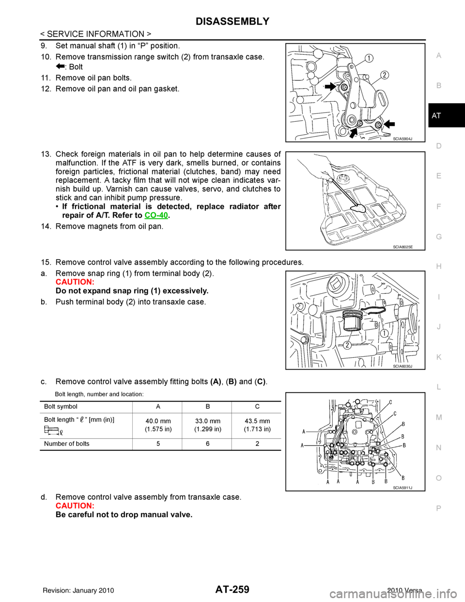
9. Set manual shaft (1) in “P” position.
10. Remove transmission range switch (2) from transaxle case. : Bolt
11. Remove oil pan bolts.
12. Remove oil pan and oil pan gasket.
13. Check foreign materials in oil pan to help determine causes of malfunction. If the ATF is very dark, smells burned, or contains
foreign particles, frictional material (clutches, band) may need
replacement. A tacky film that will not wipe clean indicates var-
nish build up. Varnish can cause valves, servo, and clutches to
stick and can inhibit pump pressure.
•If frictional material is detected, replace radiator after
repair of A/T. Refer to CO-40
.
14. Remove magnets from oil pan.
15. Remove control valve assembly according to the following procedures.
a. Remove snap ring (1) from terminal body (2). CAUTION:
Do not expand snap ring (1) excessively.
b. Push terminal body (2) into transaxle case.
c. Remove control valve assembly fitting bolts (A), (B) and ( C).
Bolt length, number and location:
d. Remove control valve assembly from transaxle case.
CAUTION:
Be careful not to drop manual valve.
SCIA5904J
SCIA8025E
SCIA6030J
Bolt symbol ABC
Bolt length “ ” [mm (in)] 40.0 mm
(1.575 in) 33.0 mm
(1.299 in) 43.5 mm
(1.713 in)
Number of bolts 562
SCIA5911J
Revision: January 20102010 Versa
Page 388 of 3745
ASSEMBLYAT-371
< SERVICE INFORMATION >
DE
F
G H
I
J
K L
M A
B
AT
N
O P
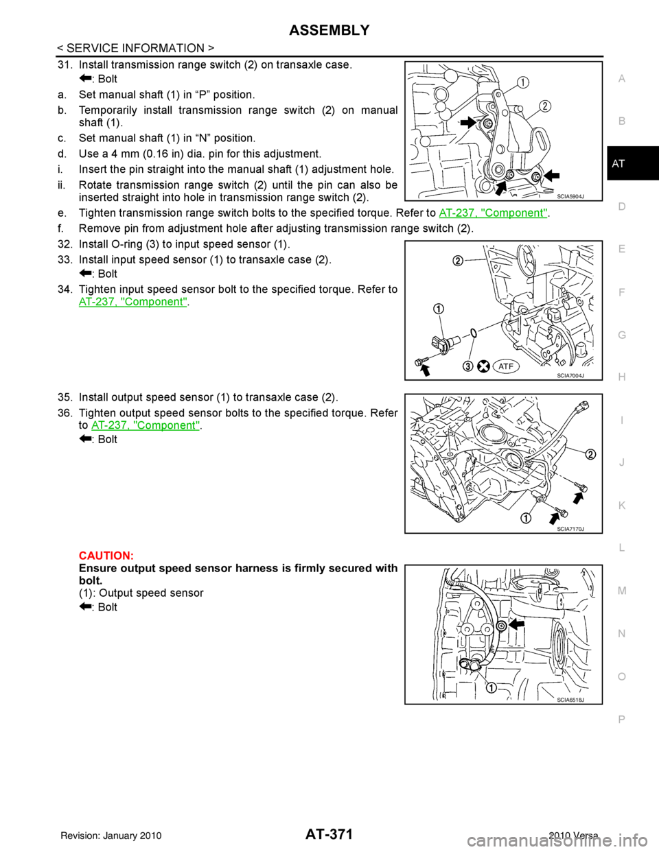
31. Install transmission range switch (2) on transaxle case. : Bolt
a. Set manual shaft (1) in “P” position.
b. Temporarily install transmission range switch (2) on manual shaft (1).
c. Set manual shaft (1) in “N” position.
d. Use a 4 mm (0.16 in) dia. pin for this adjustment.
i. Insert the pin straight into the manual shaft (1) adjustment hole.
ii. Rotate transmission range switch (2) until the pin can also be inserted straight into hole in transmission range switch (2).
e. Tighten transmission range switch bolts to the specified torque. Refer to AT-237, "
Component".
f. Remove pin from adjustment hole after adjusting transmission range switch (2).
32. Install O-ring (3) to input speed sensor (1).
33. Install input speed sensor (1) to transaxle case (2). : Bolt
34. Tighten input speed sensor bolt to the specified torque. Refer to AT-237, "
Component".
35. Install output speed sensor (1) to transaxle case (2).
36. Tighten output speed sensor bolts to the specified torque. Refer to AT-237, "
Component".
: Bolt
CAUTION:
Ensure output speed sensor harness is firmly secured with
bolt.
(1): Output speed sensor
: Bolt
SCIA5904J
SCIA7004J
SCIA7170J
SCIA6518J
Revision: January 20102010 Versa
Page 597 of 3745
BL-88
< SERVICE INFORMATION >
INTELLIGENT KEY SYSTEM
System Description
INFOID:0000000005396599
• The Intelligent Key system is a system that makes it possible to lock and unlock the door locks (door lock/
unlock function), and start the engine (engine start func tion) by carrying around the Intelligent Key (without
some key operation), which operates based on the results of electronic ID verification using two-way com-
munications between the Intelligent Key and the vehicle (Intelligent Key unit).
• Vehicles equipped with a manual transmission include a key interlock solenoid located in the steering col- umn to prevent accidental shut-off of the ignition sw itch and locking of the steering wheel during driving con-
dition when the vehicle is moving.
CAUTION:
The driver should always carry the Intelligent Key
• Operation of the remote controller buttons on the Inte lligent Key also provides the same functions as the
remote control entry system. (Remote keyless entry functions)
• If an action that does not meet the operating conditions of the Intelligent Key system is taken, the buzzer
goes off to inform the driver. (Warning chime functions)
• When a door lock is locked or unlocked with request switch or remote controller button operation, the hazard
lamps flash and the buzzer (outside vehicle) sounds (Hazard and buzzer reminder function).
• Even if the Intelligent Key battery is completely discharged, the door locks can be locked and unlocked and the engine started with the mechanical key built into the Intelligent Key.
• The settings for each function can be changed with the CONSULT-III.
• If an Intelligent Key is lost, a new Intelligent Key can be registered. A maximum of 4 Intelligent Keys can be registered.
• It has been made possible to diagnose the system and r egister an Intelligent Key with the CONSULT-III.
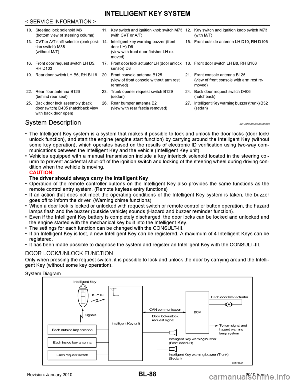
DOOR LOCK/UNLOCK FUNCTION
Only when pressing the request switch, it is possible to lock and unlock the door by carrying around the Intelli-
gent Key (without some key operation).
System Diagram
10. Steering lock solenoid M6
(bottom view of steering column) 11. Key switch and ignition knob switch M73
(with CVT or A/T) 12. Key switch and ignition knob switch M73
(with M/T)
13. CVT or A/T shift selector (park posi- tion switch) M38
(without M/T) 14. Intelligent key warning buzzer (front
door LH) D6
(view with front door finisher LH re-
moved) 15. Front outside antenna LH D10, RH D106
16. Front door request switch LH D5, RH D103 17. Front door lock actuator LH (door unlock
sensor) D3 18. Front door switch LH B8, RH B108
19. Rear door switch LH B6, RH B116 20. Front console antenna B125 (view of front console without arm rest
removed)21. Front console antenna B125
(view of front console with arm rest re-
moved)
22. Rear floor antenna B126 (behind rear seat) 23. Trunk opener request switch B129
(sedan) 24. Back door request switch D406
(hatchback)
25. Back door lock assembly (back door switch) D405 (hatchback view
with back door open) 26. Rear bumper antenna B2
(view with rear fascia removed) 27. Intelligent Key warn
ing buzzer (trunk) B32
(sedan)
LIIA2926E
Revision: January 20102010 Versa