2010 NISSAN TIIDA manual transmission
[x] Cancel search: manual transmissionPage 2687 of 3745

HOW TO USE THIS MANUALGI-21
< SERVICE INFORMATION >
C
DE
F
G H
I
J
K L
M B
GI
N
O PFR, RR Front, RearLH, RH Left-Hand, Right-Hand M/T Manual Transaxle/Transmission
OD Overdrive
P/S Power Steering
SAE Society of Automotive Engineers, Inc.
SDS Service Data and Specifications
SST Special Service Tools
2WD 2-Wheel Drive
2
22nd range Second [Gear (2GR)]
2
12nd range First [Gear (1GR)]
1
21st range Second [Gear (2GR)]
1
11st range First [Gear (1GR)]
ABBREVIATION
DESCRIPTION
Revision: January 20102010 Versa
Page 2691 of 3745

SERVICE INFORMATION FOR ELECTRICAL INCIDENTGI-25
< SERVICE INFORMATION >
C
DE
F
G H
I
J
K L
M B
GI
N
O P
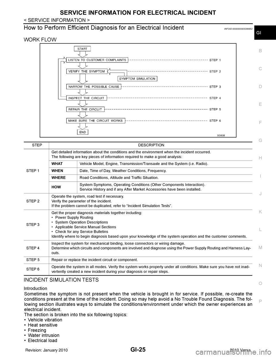
How to Perform Efficient Diagnos is for an Electrical IncidentINFOID:0000000005399852
WORK FLOW
INCIDENT SIMULATION TESTS
Introduction
Sometimes the symptom is not present when the vehicle is brought in for service. If possible, re-create the
conditions present at the time of the incident. Doi ng so may help avoid a No Trouble Found Diagnosis. The fol-
lowing section illustrates ways to simulate the c onditions/environment under which the owner experiences an
electrical incident.
The section is broken into the six following topics:
• Vehicle vibration
• Heat sensitive
• Freezing
• Water intrusion
• Electrical load
SGI838
STEP DESCRIPTION
STEP 1 Get detailed information about the conditions and the environment when the incident occurred.
The following are key pieces of information required to make a good analysis:
WHAT
Vehicle Model, Engine, Transmission/Transaxle and the System (i.e. Radio).
WHEN Date, Time of Day, Weather Conditions, Frequency.
WHERE Road Conditions, Altitude and Traffic Situation.
HOW System Symptoms, Operating Conditions (Other Components Interaction).
Service History and if any After Market Accessories have been installed.
STEP 2 Operate the system, road test if necessary.
Verify the parameter of the incident.
If the problem cannot be duplicated, refer to “Incident Simulation Tests”.
STEP 3 Get the proper diagnosis materials together including:
• Power Supply Routing
• System Operation Descriptions
• Applicable Service Manual Sections
• Check for any Service Bulletins
Identify where to begin diagnosis based upon your knowledge of the system operation and the customer comments.
STEP 4 Inspect the system for mechanical binding, loose connectors or wiring damage.
Determine which circuits and components are involved and diagnose using the Power Supply Routing and Harness Lay-
outs.
STEP 5 Repair or replace the incident circuit or component.
STEP 6 Operate the system in all modes. Verify the system works properly under all conditions. Make sure you have not inad-
vertently created a new incident during your diagnosis or repair steps.
Revision: January 20102010 Versa
Page 2701 of 3745

CONSULT-III CHECKING SYSTEMGI-35
< SERVICE INFORMATION >
C
DE
F
G H
I
J
K L
M B
GI
N
O PCONSULT-III CHECKING SYSTEM
DescriptionINFOID:0000000005399854
• CONSULT-III is a hand-held type tester. When it is connected with a diagnostic connector equipped on the vehicle side, it will communicate with the contro l unit equipped in the vehicle and then enable various kinds
of diagnostic tests.
• Refer to CONSULT-III Operator's Manual for more information.
Function and System ApplicationINFOID:0000000005399855
x: Applicable.
*1: If equipped.
*2: With automatic transmission (A/T).
*3: With continuously variable transmission (CVT). Diagnostic test mode
Function
ENGINE
ABS*
1
AIR BAG EPS
IPDM E/R BCM
METER/M&A
INTELLIGENT KEY*
1
TRANSMISSION*
2
TRANSMISSION*
3
Work Support This mode enables a technician to adjust some devices faster and
more accurately by following indications on CONSULT-III. xx - - - x - - xx
Self Diagnostic Results Self-diagnostic results can be read and erased quickly. x x x x x x x x x x
Data Monitor Input/Output data in the ECU can be read. x x x x x x x x x x
CAN Diagnostic Support
Monitor The communication condition of CAN communication line can be
read.
xx - xxxxxxx
Active Test Diagnostic Test Mode in which CONSULT-III drives actuators apart
from ECU shifting some parameters in a specified range. xx - - xx - x - -
Function Test This mode can show results of self-diagnosis of ECU with either
"OK" or "NG". For engines, more practical tests regarding sensors/
switches and/or actuators are available. xxx - - - - - xx
DTC & SRT Confirmation The results of SRT (System Readiness Test) and the self-diagno-
sis status/result can be confirmed. x- - - - - - -x-
Ecu Identification ECM/ECU part number can be read. x x x x - x - x x x
Configuration Sets control module parameters to match vehicle options. - - - - - x - - - -
Special Function Other results or histories, etc that are recorded in ECU are dis-
played. --x------x
Revision: January 20102010 Versa
Page 2706 of 3745

GI-40
< SERVICE INFORMATION >
TOW TRUCK TOWING
TOW TRUCK TOWING
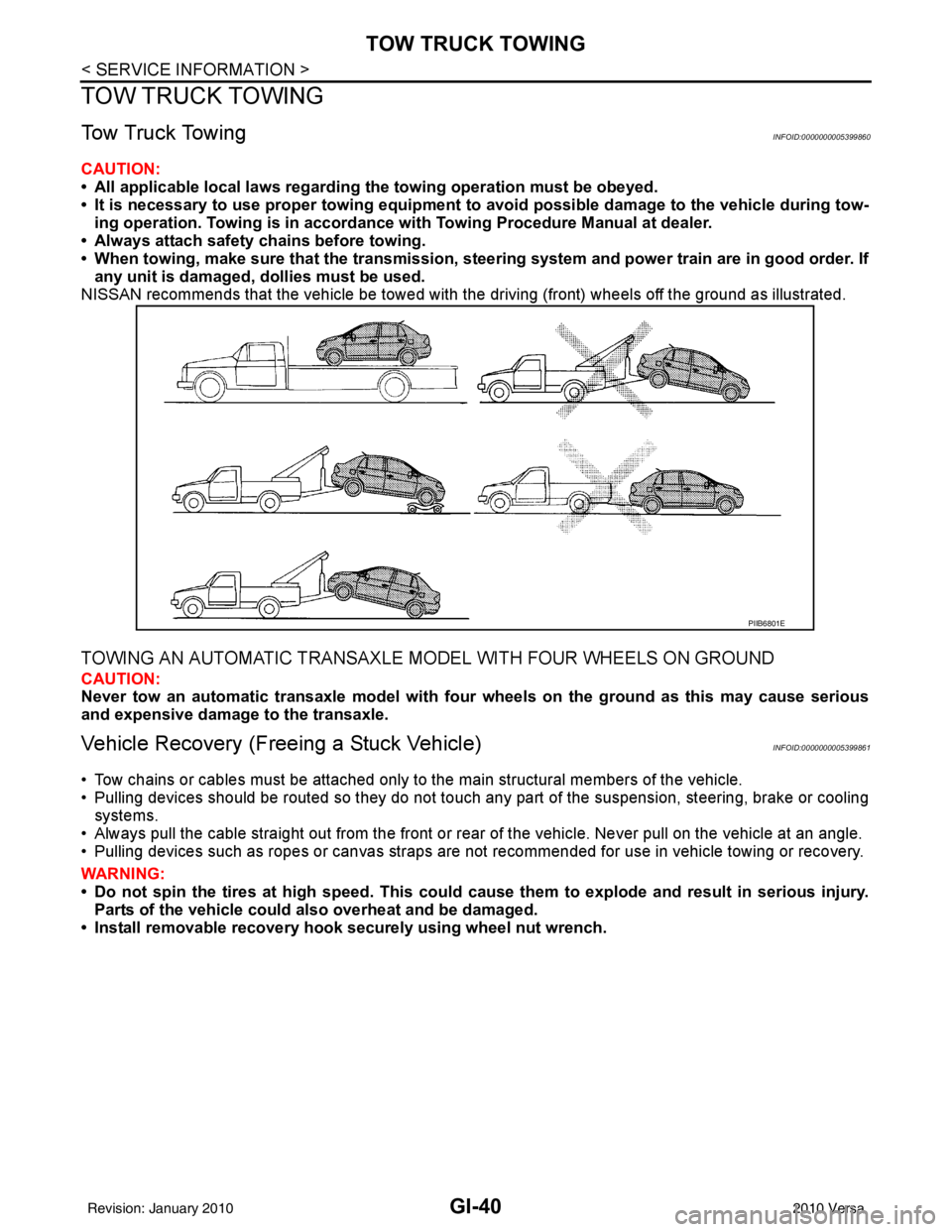
Tow Truck TowingINFOID:0000000005399860
CAUTION:
• All applicable local laws regarding the towing operation must be obeyed.
• It is necessary to use proper towi ng equipment to avoid possible damage to the vehicle during tow-
ing operation. To wing is in accordance with Towing Procedure Manual at dealer.
• Always attach safety chains before towing.
• When towing, make sure that the transmission, steering system and power train are in good order. If
any unit is damaged, dollies must be used.
NISSAN recommends that the vehicle be towed with the driving (front) wheels off the ground as illustrated.
TOWING AN AUTOMATIC TRANSAXLE MODEL WITH FOUR WHEELS ON GROUND
CAUTION:
Never tow an automatic transaxle model with four wheels on the ground as this may cause serious
and expensive damage to the transaxle.
Vehicle Recovery (Freeing a Stuck Vehicle)INFOID:0000000005399861
• Tow chains or cables must be attached only to the main structural members of the vehicle.
• Pulling devices should be routed so they do not touch any part of the suspension, steering, brake or cooling
systems.
• Always pull the cable straight out from the front or r ear of the vehicle. Never pull on the vehicle at an angle.
• Pulling devices such as ropes or canvas straps are not recommended for use in vehicle towing or recovery.
WARNING:
• Do not spin the tires at high sp eed. This could cause them to explode and result in serious injury.
Parts of the vehicle could also overheat and be damaged.
• Install removable recovery hook securely using wheel nut wrench.
PIIB6801E
Revision: January 20102010 Versa
Page 3146 of 3745

PERIODIC MAINTENANCEMA-11
< SERVICE INFORMATION >
C
DE
F
G H
I
J
K
M A
B
MA
N
O P
Abbreviations: R = Replace. I = Inspect. Corr ect or replace if necessary. L = Lubricate.
(1) Using transmission fluid other than Genuine NISSAN CVT Fluid NS-2 will damage the CVT, which is not covered by the
NISSAN new vehicle limited warranty.
(3) Refer to “Tire rotation” under the “GENERAL MAINTENANCE” heading earlier in this section.
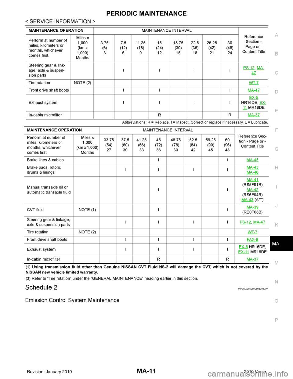
Schedule 2INFOID:0000000005394797
Emission Control System Maintenance
Steering gear & link-
age, axle & suspen-
sion parts IIII
PS-12, MA-
47
Tire rotation
NOTE (2) WT-7
Front drive shaft bootsIIIIMA-47
Exhaust system IIIIEX-5
HR16DE, EX-
11 MR18DE
In-cabin microfilter RRMA-37
MAINTENANCE OPERATION MAINTENANCE INTERVAL
Reference Section -
Page or -
Content Title
Perform at number of
miles, kilometers or
months, whichever
comes first. Miles x
1,000
(km x
1,000)
Months 3.75
(6)3 7.5
(12) 6 11 . 2 5
(18) 9 15
(24) 12 18.75
(30)15 22.5
(36) 18 26.25
(42)21 30
(48) 24
MAINTENANCE OPERATION MAINTENANCE INTERVAL
Reference Sec-tion - Page or - Content Title
Perform at number of
miles, kilometers or
months, whichever
comes first. Miles x
1,000
(km x 1,000) Months 33.75
(54)27 37.5
(60) 30 41.25
(66)33 45
(72) 36 48.75
(78)39 52.5
(84) 42 56.25
(90)45 60
(96) 48
Brake lines & cables IIMA-45
Brake pads, rotors,
drums & linings II I I MA-45
MA-46
Manual transaxle oil or
automatic transaxle fluid IIMA-41
(RS5F91R) MA-42
(RS6F94R)
MA-43
(A/T)
CVT fluid NOTE (1) IIMA-39
(RE0F08B)
Steering gear & linkage,
axle & suspension parts II I I
PS-12
, MA-47
Tire rotationNOTE (2) WT-7
Front drive shaft bootsII IIFAX-9
Exhaust system II IIEX-5 HR16DE,
EX-11
MR18DE
In-cabin microfilter RRMA-37
Revision: January 20102010 Versa
Page 3149 of 3745

MA-14
< SERVICE INFORMATION >
RECOMMENDED FLUIDS AND LUBRICANTS
RECOMMENDED FLUIDS AND LUBRICANTS
Fluids and LubricantsINFOID:0000000005394798
*1: For further details, see “Engine Oil Recommendation”.
*2: If genuine NISSAN gear oil is not available, API GL-4, Viscosity SAE 75W-80 may be used as a temporary replacement. However
use Genuine NISSAN gear oil as soon as it is possible.
*3: Using transaxle fluid other than Genuine NISSAN CVT Fluid NS-2 will damage the CVT, which is not covered by the NISSAN
new vehicle limited warranty.
*4: Available in mainland U.S.A. through a NISSAN dealer.
*5: For further details, see “Air conditioner specification label”.
*6: If Genuine NISSAN Matic S ATF is not available, Genuine NISSIAN Matic D ATF may also be used. Using automatic transmission
other than Genuine NISSAN Matic S or Genuine NISSIAN Matic D ATF will cause deteri oration in driveability and automatic transmis-
sion durability, and may damage the automatic transmission, which is not covered by NISSAN new vehicle limited warranty.
SAE Viscosity NumberINFOID:0000000005394799
NISSAN recommends the use of an energy conservi ng oil in order to improve fuel economy.
DescriptionCapacity (Approximate)
Recommended Fluids/Lubricants
Liter US measure Imp measure
Fuel 50.0 13 1/4 gal 11 galUnleaded gasoline with an octane rat-
ing of at least 87 AKI (RON 91)
Engine oil
Drain and refill With oil filter
change
HR16DE 3.0 3 1/8 qt 2 5/8 qt
• Engine oil with API Certification Mark *1
• Viscosity SAE 5W-30
MR18DE 4.1 4 3/8 qt 3 5/8 qt
Without oil
filter change HR16DE 2.8
3 qt 2 1/2 qt
MR18DE 3.9 4 1/8 qt 3 3/8 qt
Dry engine (engine overhaul) HR16DE 3.5 3 3/4 qt 3 1/8 qt
MR18DE 4.9 5 1/8 qt 4 3/8 qt
Cooling system
(with reservoir at max level) HR16DE 6.3 6 5/8 qt 5 1/2 qt Genuine
NISSAN Long Life Anti-freeze
Coolant or equivalent
MR18DE 6.8 7 1/4 qt 6 qt
Manual transaxle fluid (MTF) 5MT
2.6 5 1/2 pt 4 5/8 pt Genuine NISSAN Manual Transmis-
sion Fluid (MTF) HQ Multi 75W-85 or
API GL-4, Viscosity SAE 75W-85
6MT 2.0 4 1/4 pt 3 1/2 pt Genuine NISSAN gear oil (XT4447
M+) 75W-80, Genuine NISSAN gear oil
(ETL8997B) 75W-80, or equivalent *2
Automatic transaxle fluid (ATF) HR16DE 7.7 8 1/8 qt 6 3/4 qt
Genuine NISSAN Matic S ATF recom-
mended *6
MR18DE 7.9 8 3/8 qt 7 qt
CVT fluid RE0F08B 7.4 7 7/8 qt 6 1/2 qt Genuine NISSAN CVT Fluid NS-2 *3
Brake and clutch fluid ———Genuine NISSAN Su
per Heavy Duty
Brake Fluid*4 or equivalent DOT 3 (US
FMVSS No. 116)
Multi-purpose grease ——— NLGI No. 2 (Lithium soap base)
Windshield washer fluid 4.5 4 3/4 qt 4 qtGenuine NISSAN Windshield Washer
Concentrate Cleaner & Anti-Freeze or
equivalent
Air conditioning system refrigerant 0.45 ± 0.05 kg 0.99 ± 0.11 lb 0.99 ± 0.11 lb HFC-134a (R-134a) *5
Air conditioning system oil MR18DE
Type 1 and
HR16DE
120 m
4.1 fl oz 4.2 fl oz NISSAN A/C System Lubricant Type R
or equivalent *5
MR18DE
Typ e 2 100 m
3.4 fl oz 3.5 fl oz NISSAN A/C System Lubricant Type S
or equivalent *5
Revision: January 20102010 Versa
Page 3185 of 3745

MT-1
TRANSMISSION/TRANSAXLE
DE
F
G H
I
J
K L
M
SECTION MT
A
B
MT
N
O P
CONTENTS
MANUAL TRANSAXLE
RS5F91R
SERVICE INFORMATION .. ..........................
3
PRECAUTIONS .............................................. .....3
Precaution for Supplemental Restraint System
(SRS) "AIR BAG" and "SEAT BELT PRE-TEN-
SIONER" ............................................................. ......
3
Precaution Necessary for Steering Wheel Rota-
tion After Battery Disconnect ............................... ......
3
Precaution for Procedure without Cowl Top Cover ......4
Service Notice or Precaution .....................................4
PREPARATION ...................................................5
Special Service Tools ........................................ ......5
Commercial Service Tools .......................................7
NOISE, VIBRATION AND HARSHNESS
(NVH) TROUBLESHOOTING .............................
8
NVH Troubleshooting Chart ................................ ......8
DESCRIPTION ....................................................9
System Diagram .................................................. ......9
System Description ...................................................9
M/T OIL ...............................................................11
Draining ...................................................................11
Refilling ...................................................................11
Inspection ................................................................11
SIDE OIL SEAL ..................................................12
Removal and Installation .........................................12
POSITION SWITCH ........................................ ....13
Checking ............................................................. ....13
CONTROL LINKAGE .........................................14
Exploded View .................................................... ....14
Removal and Installation .........................................14
Inspection ............................................................ ....15
AIR BREATHER HOSE ......................................16
Exploded View .................................................... ....16
Removal and Installation ..................................... ....16
TRANSAXLE ASSEMBLY ................................17
Exploded View .........................................................17
Removal and Installation .........................................17
Disassembly and Assembly .....................................18
INPUT SHAFT AND GEAR ...............................36
Disassembly and Assembly .....................................36
MAINSHAFT AND GEAR .................................37
Disassembly and Assembly .....................................37
FINAL DRIVE ....................................................41
Disassembly and Assembly .....................................41
SHIFT CONTROL ..............................................42
Inspection ................................................................42
SERVICE DATA AND SPECIFICATIONS
(SDS) .................................................................
43
General Specification ..............................................43
RS6F94R
SERVICE INFORMATION .. .........................
44
PRECAUTIONS .................................................44
Precaution for Supplemental Restraint System
(SRS) "AIR BAG" and "SEAT BELT PRE-TEN-
SIONER" ............................................................. ....
44
Precaution Necessary for Steering Wheel Rota-
tion After Battery Disconnect ...................................
44
Precaution for Procedure without Cowl Top Cover ....45
Precaution ...............................................................45
PREPARATION .................................................46
Special Service Tool ................................................46
Commercial Service Tool ........................................48
NOISE, VIBRATION AND HARSHNESS
(NVH) TROUBLESHOOTING ...........................
51
NVH Troubleshooting Chart ....................................51
Revision: January 20102010 Versa