2010 NISSAN TIIDA Green
[x] Cancel search: GreenPage 664 of 3745

INTELLIGENT KEY SYSTEMBL-155
< SERVICE INFORMATION >
C
DE
F
G H
J
K L
M A
B
BL
N
O P
"LOCK" Warning Lamp (With M/T) CheckINFOID:0000000005396634
1.CHECK WARNING LAMP OPERATION
With CONSULT-III
• Check “INDICATOR” in “ACTIVE TEST” mode with CONSULT-III.
• Select “KNOB ON”.
“LOCK” warning lamp should illuminate.
Without CONSULT-III
1. Turn ignition switch OFF.
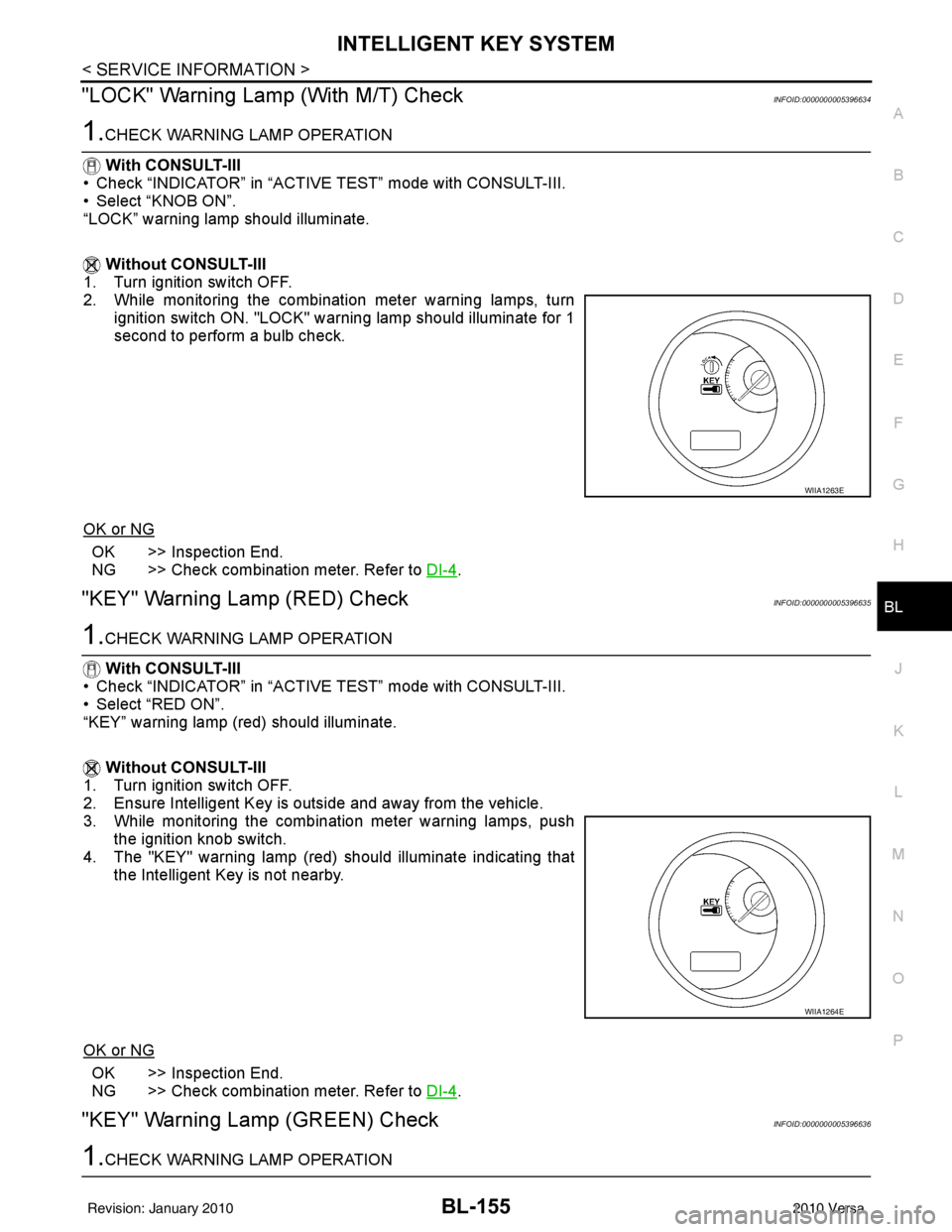
2. While monitoring the combination meter warning lamps, turn
ignition switch ON. "LOCK" warning lamp should illuminate for 1
second to perform a bulb check.
OK or NG
OK >> Inspection End.
NG >> Check combination meter. Refer to DI-4
.
"KEY" Warning Lamp (RED) CheckINFOID:0000000005396635
1.CHECK WARNING LAMP OPERATION
With CONSULT-III
• Check “INDICATOR” in “ACTIVE TEST” mode with CONSULT-III.
• Select “RED ON”.
“KEY” warning lamp (red) should illuminate.
Without CONSULT-III
1. Turn ignition switch OFF.
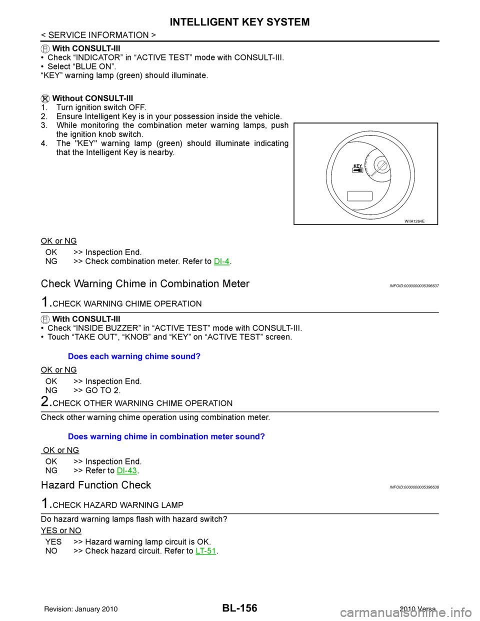
2. Ensure Intelligent Key is outside and away from the vehicle.
3. While monitoring the combination meter warning lamps, push the ignition knob switch.
4. The "KEY" warning lamp (red) should illuminate indicating that the Intelligent Key is not nearby.
OK or NG
OK >> Inspection End.
NG >> Check combination meter. Refer to DI-4
.
"KEY" Warning Lamp (GREEN) CheckINFOID:0000000005396636
1.CHECK WARNING LAMP OPERATION
WIIA1263E
WIIA1264E
Revision: January 20102010 Versa
Page 665 of 3745

BL-156
< SERVICE INFORMATION >
INTELLIGENT KEY SYSTEM
With CONSULT-III
• Check “INDICATOR” in “ACTIVE TEST” mode with CONSULT-III.
• Select “BLUE ON”.
“KEY” warning lamp (green) should illuminate.
Without CONSULT-III
1. Turn ignition switch OFF.
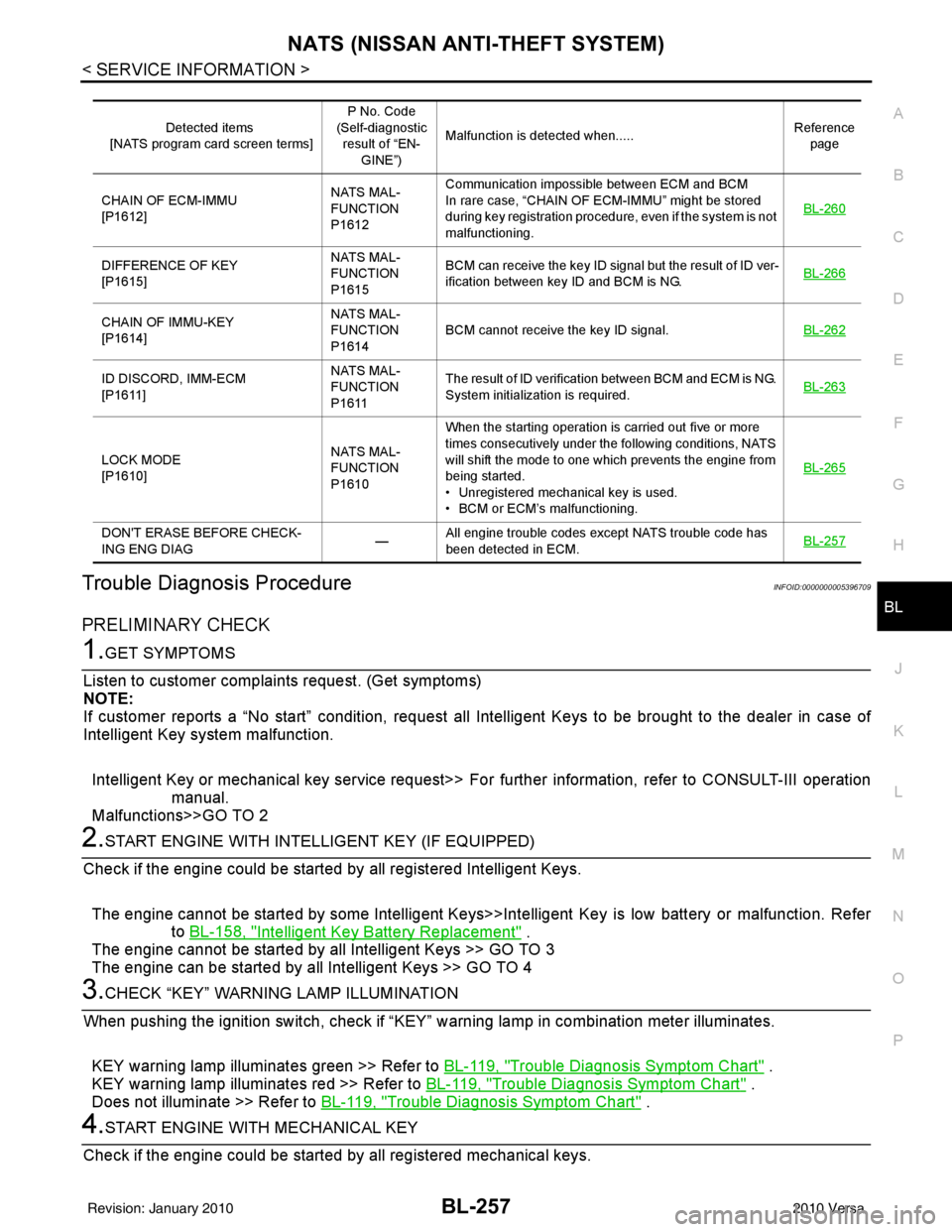
2. Ensure Intelligent Key is in your possession inside the vehicle.
3. While monitoring the combination meter warning lamps, push the ignition knob switch.
4. The "KEY" warning lamp (green) should illuminate indicating that the Intelligent Key is nearby.
OK or NG
OK >> Inspection End.
NG >> Check combination meter. Refer to DI-4
.
Check Warning Chime in Combination MeterINFOID:0000000005396637
1.CHECK WARNING CHIME OPERATION
With CONSULT-III
• Check “INSIDE BUZZER” in “ACTIVE TEST” mode with CONSULT-III.
• Touch “TAKE OUT”, “KNOB” and “KEY” on “ACTIVE TEST” screen.
OK or NG
OK >> Inspection End.
NG >> GO TO 2.
2.CHECK OTHER WARNING CHIME OPERATION
Check other warning chime operation using combination meter.
OK or NG
OK >> Inspection End.
NG >> Refer to DI-43
.
Hazard Function CheckINFOID:0000000005396638
1.CHECK HAZARD WARNING LAMP
Do hazard warning lamps flash with hazard switch?
YES or NO
YES >> Hazard warning lamp circuit is OK.
NO >> Check hazard circuit. Refer to LT- 5 1
.
WIIA1264E
Does each warning chime sound?
Does warning chime in combination meter sound?
Revision: January 20102010 Versa
Page 766 of 3745

NATS (NISSAN ANTI-THEFT SYSTEM)BL-257
< SERVICE INFORMATION >
C
DE
F
G H
J
K L
M A
B
BL
N
O P
Trouble Diagnosis ProcedureINFOID:0000000005396709
PRELIMINARY CHECK
1.GET SYMPTOMS
Listen to customer complain ts request. (Get symptoms)
NOTE:
If customer reports a “No start” condition, request all Intelligent Keys to be brought to the dealer in case of
Intelligent Key system malfunction.
Intelligent Key or mechanical key service request>> Fo r further information, refer to CONSULT-III operation
manual.
Malfunctions>>GO TO 2
2.START ENGINE WITH INTELLIGENT KEY (IF EQUIPPED)
Check if the engine could be started by all registered Intelligent Keys.
The engine cannot be started by some Intelligent Keys>>Int elligent Key is low battery or malfunction. Refer
to BL-158, "
Intelligent Key Battery Replacement" .
The engine cannot be started by all Intelligent Keys >> GO TO 3
The engine can be started by all Intelligent Keys >> GO TO 4
3.CHECK “KEY” WARNING LAMP ILLUMINATION
When pushing the ignition switch, check if “KEY” warning lamp in combination meter illuminates.
KEY warning lamp illuminates green >> Refer to BL-119, "
Trouble Diagnosis Symptom Chart" .
KEY warning lamp illuminates red >> Refer to BL-119, "
Trouble Diagnosis Symptom Chart" .
Does not illuminate >> Refer to BL-119, "
Trouble Diagnosis Symptom Chart" .
4.START ENGINE WITH MECHANICAL KEY
Check if the engine could be started by all registered mechanical keys.
Detected items
[NATS program card screen terms] P No. Code
(Self-diagnostic result of “EN-
GINE”) Malfunction is detected when.....
Reference
page
CHAIN OF ECM-IMMU
[P1612] NATS MAL-
FUNCTION
P1612Communication impossible between ECM and BCM
In rare case, “CHAIN OF ECM-IMMU” might be stored
during key registration procedure, even if the system is not
malfunctioning.
BL-260
DIFFERENCE OF KEY
[P1615]NATS MAL-
FUNCTION
P1615BCM can receive the key ID signal but the result of ID ver-
ification between key ID and BCM is NG.
BL-266
CHAIN OF IMMU-KEY
[P1614]NATS MAL-
FUNCTION
P1614
BCM cannot receive the key ID signal.
BL-262
ID DISCORD, IMM-ECM
[P1611]NATS MAL-
FUNCTION
P1611The result of ID verification between BCM and ECM is NG.
System initialization is required.
BL-263
LOCK MODE
[P1610]NATS MAL-
FUNCTION
P1610When the starting operation is carried out five or more
times consecutively under the following conditions, NATS
will shift the mode to one which prevents the engine from
being started.
• Unregistered mechanical key is used.
• BCM or ECM’s malfunctioning.
BL-265
DON'T ERASE BEFORE CHECK-
ING ENG DIAG
—All engine trouble codes except NATS trouble code has
been detected in ECM.
BL-257
Revision: January 20102010 Versa
Page 916 of 3745
![NISSAN TIIDA 2010 Service Repair Manual BRC-26
< SERVICE INFORMATION >[ABS]
TROUBLE DIAGNOSIS FOR
SELF-DIAGNOSTIC ITEMS
TROUBLE DIAGNOSIS FOR SELF-DIAGNOSTIC ITEMS
Wheel Sensor SystemINFOID:0000000005397040
INSPECTION PROCEDURE
1.CONNECTOR NISSAN TIIDA 2010 Service Repair Manual BRC-26
< SERVICE INFORMATION >[ABS]
TROUBLE DIAGNOSIS FOR
SELF-DIAGNOSTIC ITEMS
TROUBLE DIAGNOSIS FOR SELF-DIAGNOSTIC ITEMS
Wheel Sensor SystemINFOID:0000000005397040
INSPECTION PROCEDURE
1.CONNECTOR](/manual-img/5/57397/w960_57397-915.png)
BRC-26
< SERVICE INFORMATION >[ABS]
TROUBLE DIAGNOSIS FOR
SELF-DIAGNOSTIC ITEMS
TROUBLE DIAGNOSIS FOR SELF-DIAGNOSTIC ITEMS
Wheel Sensor SystemINFOID:0000000005397040
INSPECTION PROCEDURE
1.CONNECTOR INSPECTION
Disconnect the ABS actuator and electric unit (control unit) connector E33 and wheel sensor of malfunctioning
code.
Check the terminals for deformation, disconnection, looseness or damage.
OK or NG
OK >> GO TO 2.
NG >> Repair or replace as necessary.
2.CHECK WHEEL SENSOR OUTPUT SIGNAL
1. Connect ABS active wheel sensor tester (J-45741) to wheel sensor using appropriate adapter.
2. Turn on the ABS active wheel sensor tester power switch. NOTE:
The green POWER indicator should illuminate. If the POWER indicator does not illuminate, replace the
battery in the ABS active wheel sensor tester before proceeding.
3. Spin the wheel of the vehicle by hand and observe the red SENSOR indicator on the ABS active wheel
sensor tester. The red SENSOR indicator should flash on and off to indicate an output signal.
NOTE:
If the red SENSOR indicator illuminates but does not flash, reverse the polarity of the tester leads and
retest.
Does the ABS active wheel sensor tester detect a signal?
YES >> GO TO 3.
NO >> Replace the wheel sensor. Refer to BRC-34, "
Removal and Installation".
3.CHECK TIRES
Check for inflation pressure, wear and size of each tire. Refer to WT-28
.
Are tire pressure and size correct and is tire wear within specifications?
YES >> GO TO 4.
NO >> Adjust tire pressure or replace tire(s).
4.CHECK WHEEL BEARINGS
Check wheel bearing axial end play. Refer to FAX-6, "
On-Vehicle Inspection and Service" or RAX-6, "On-Vehi-
cle Inspection and Service".
OK or NG
OK >> GO TO 5.
NG >> Repair or replace as necessary. Refer to FA X - 6 , "
Removal and Installation" or RAX-6, "Removal
and Installation".
5.CHECK WIRING HARNESS FOR SHORT CIRCUIT
1. Turn ignition switch OFF.
2. Disconnect ABS actuator and elec tric unit (control unit) connec-
tor and wheel sensor connector of malfunction code No.
3. Check continuity between wheel sensor harness connector ter- minals and ground.
OK or NG
OK >> GO TO 6.
NG >> Repair the circuit.
6.CHECK WIRING HARNESS FOR OPEN CIRCUIT Continuity should not exist.
WFIA0498E
Revision: January 20102010 Versa
Page 957 of 3745
![NISSAN TIIDA 2010 Service Repair Manual TROUBLE DIAGNOSIS FOR SELF-DIAGNOSTIC ITEMS
BRC-67
< SERVICE INFORMATION > [VDC/TCS/ABS]
C
D
E
G H
I
J
K L
M A
B
BRC
N
O P
TROUBLE DIAGNOSIS FOR SELF-DIAGNOSTIC ITEMS
Wheel Sensor System InspectionIN NISSAN TIIDA 2010 Service Repair Manual TROUBLE DIAGNOSIS FOR SELF-DIAGNOSTIC ITEMS
BRC-67
< SERVICE INFORMATION > [VDC/TCS/ABS]
C
D
E
G H
I
J
K L
M A
B
BRC
N
O P
TROUBLE DIAGNOSIS FOR SELF-DIAGNOSTIC ITEMS
Wheel Sensor System InspectionIN](/manual-img/5/57397/w960_57397-956.png)
TROUBLE DIAGNOSIS FOR SELF-DIAGNOSTIC ITEMS
BRC-67
< SERVICE INFORMATION > [VDC/TCS/ABS]
C
D
E
G H
I
J
K L
M A
B
BRC
N
O P
TROUBLE DIAGNOSIS FOR SELF-DIAGNOSTIC ITEMS
Wheel Sensor System InspectionINFOID:0000000005612159
INSPECTION PROCEDURE
1.CONNECTOR INSPECTION
Disconnect the ABS actuator and electric unit (control unit) connector E33 and wheel sensor of malfunctioning
code.
Check the terminals for deformation, disconnection, looseness or damage.
OK or NG
OK >> GO TO 2.
NG >> Repair or replace as necessary.
2.CHECK WHEEL SENSOR OUTPUT SIGNAL
1. Connect ABS active wheel sensor tester (J- 45741) to wheel sensor using appropriate adapter.
2. Turn on the ABS active wheel sensor tester power switch.
NOTE:
The green POWER indicator should illuminate. If the POWER indicator does not illuminate, replace the
battery in the ABS active wheel sensor tester before proceeding.
3. Spin the wheel of the vehicle by hand and observe the red SENSOR indicator on the ABS active wheel
sensor tester. The red SENSOR indicator should flash on and off to indicate an output signal.
NOTE:
If the red SENSOR indicator illuminates but does not flash, reverse the polarity of the tester leads and
retest.
Does the ABS active wheel s ensor tester detect a signal?
YES >> GO TO 3.
NO >> Replace the wheel sensor. Refer to BRC-86, "
Removal and Installation".
3.CHECK TIRES
Check for inflation pressure, wear and size of each tire. Refer to WT-28, "
Tire".
Are tire pressure and size correct and is tire wear within specifications?
YES >> GO TO 4.
NO >> Adjust tire pressure or replace tire(s).
4.CHECK WHEEL BEARINGS
Check wheel bearing axial end play. Refer to FA X - 6 , "
On-Vehicle Inspection and Service" or RAX-6, "On-Vehi-
cle Inspection and Service".
OK or NG
OK >> GO TO 5.
NG >> Repair or replace as necessary. Refer to FAX-6, "
Removal and Installation" (front) or RAX-6,
"Removal and Installation" (rear).
5.CHECK WIRING HARNESS FOR SHORT CIRCUIT
1. Turn the ignition switch OFF.
2. Disconnect ABS actuator and electric unit (control unit) connec- tor and wheel sensor connector of malfunction code No.
3. Check continuity between wheel sensor harness connector ter- minals and ground.
OK or NG
OK >> GO TO 6.
NG >> Repair the circuit.
6.CHECK WIRING HARNESS FOR OPEN CIRCUIT Continuity should not exist.
WFIA0498E
Revision: January 20102010 Versa
Page 1224 of 3745

DI-14
< SERVICE INFORMATION >
COMBINATION METERS
NOTE:
Some items are not available due to vehicle specification.
*: The monitor will indicate “OFF” even though the brake warning lamp is on if either of the following conditions exist.
• The parking brake is engaged
• The brake fluid level is low
Trouble DiagnosisINFOID:0000000005395016
HOW TO PERFORM TROUBLE DIAGNOSIS
1. Confirm the symptom or customer complaint.
2. Perform preliminary check. Refer to "PRELIMINARY CHECK" .
3. According to the symptom chart, repair or replace the cause of the malfunction. Refer to DI-15, "
Symptom
Chart" .
4. Does the meter operate normally? If so, GO TO 5. If not, GO TO 2.
5. Inspection End.
PRELIMINARY CHECK
1.CHECK SELF-DIAGNOSIS OPERAT ION OF COMBINATION METER
Perform self-diagnosis of combination meter. Refer to DI-11, "
Self-Diagnosis Mode of Combination Meter" .
Does self
-diagnosis mode operate?
TURN IND [ON/OFF] X Indicates [ON/OFF] condition of turn indicator.
OIL W/L [ON/OFF] X Indicates [ON/OFF] condition of oil pressure warning lamp.
VDC/TCS IND [ON/OFF] X Indicates [ON/OFF] condition of VDC OFF indicator lamp.
ABS W/L [ON/OFF] X Indicates [ON/OFF] condition of ABS warning lamp.
SLIP IND [ON/OFF] X Indicates [ON/OFF] condition of SLIP indicator lamp.
BRAKE W/L [ON/OFF] X Indicates [ON/OFF] condition of brake warning lamp.*
KEY G W/L [ON/OFF] X Indicates [ON/OFF] condition of KEY warning lamp (green).
KEY R W/L [ON/OFF] X Indicates [ON/OFF] condition of KEY warning lamp (red).
KEY KNOB W/L [ON/OFF] X Indicates [ON/OFF] condition of LOCK warning lamp.
PNP P SW [ON/OFF] XX Indicates [ON/OFF] condition of inhibitor P switch.
PNP N SW [ON/OFF] XX Indicates [ON/OFF] condition of inhibitor N switch.
O/D OFF SW [ON/OFF] X Indicates [ON/OFF] condition of O/D OFF switch.
BRAKE SW [ON/OFF] X Indicates [ON/OFF] condition of parking brake switch.
P RANGE IND [ON/OFF] XXIndicates [ON/OFF] condition of A/T or CVT shift P range indi-
cator.
R RANGE IND [ON/OFF] XXIndicates [ON/OFF] condition of A/T or CVT shift R range indi-
cator.
N RANGE IND [ON/OFF] XXIndicates [ON/OFF] condition of A/T or CVT shift N range indi-
cator.
D RANGE IND [ON/OFF] XXIndicates [ON/OFF] condition of A/T or CVT shift D range indi-
cator.
2 RANGE IND [ON/OFF] XX Indicates [ON/OFF] condition of A/T shift 2 range indicator.
L RANGE IND [ON/OFF] XX Indicates [ON/OFF] condition of CVT shift L range indicator.
1 RANGE IND [ON/OFF] XX Indicates [ON/OFF] condition of A/T shift 1 range indicator.
CRUISE IND [ON/OFF] X Indicates [ON/OFF] condition of CRUISE indicator.
SET IND [ON/OFF] X Indicates [ON/OFF] condition of SET indicator.
O/D OFF W/L [ON/OFF] X Indicates [ON/OFF] condition of O/D OFF indicator lamp.
EPS W/L [ON/OFF] X Indicates [ON/OFF] condition of EPS warning lamp.
Display item [Unit]
MAIN
SIGNALS SELECTION
FROM MENU Contents
Revision: January 20102010 Versa
Page 2393 of 3745
![NISSAN TIIDA 2010 Service Repair Manual EM-34
< ON-VEHICLE REPAIR >[HR16DE]
FUEL INJECTOR AND FUEL TUBE
FUEL INJECTOR AND FUEL TUBE
Exploded ViewINFOID:0000000005398054
CAUTION:
Never remove or disassemble part
s unless instructed as shown. NISSAN TIIDA 2010 Service Repair Manual EM-34
< ON-VEHICLE REPAIR >[HR16DE]
FUEL INJECTOR AND FUEL TUBE
FUEL INJECTOR AND FUEL TUBE
Exploded ViewINFOID:0000000005398054
CAUTION:
Never remove or disassemble part
s unless instructed as shown.](/manual-img/5/57397/w960_57397-2392.png)
EM-34
< ON-VEHICLE REPAIR >[HR16DE]
FUEL INJECTOR AND FUEL TUBE
FUEL INJECTOR AND FUEL TUBE
Exploded ViewINFOID:0000000005398054
CAUTION:
Never remove or disassemble part
s unless instructed as shown.
Removal and InstallationINFOID:0000000005398055
WARNING:
• Put a “CAUTION: FLAMMABLE” sign in the workshop.
• Be sure to work in a well ventilate d area and furnish workshop with a CO
2 fire extinguisher.
• Do not smoke while servicing fuel system. Keep open flames and sparks away from the work area.
REMOVAL
1. Release the fuel pressure. Refer to EC-496, "Inspection".
2. Disconnect battery negative terminal. Refer to SC-7, "
Removal and Installation".
3. Remove intake manifold. Refer to EM-28, "
Exploded View".
1. Quick connector cap 2. Fuel feed hose 3. Fuel tube
4. Fuel tube protector 5. O-ring (black) 6. Clip
7. Fuel injector 8.O-ring (green)
PBIC3663E
Revision: January 20102010 Versa
Page 2395 of 3745
![NISSAN TIIDA 2010 Service Repair Manual EM-36
< ON-VEHICLE REPAIR >[HR16DE]
FUEL INJECTOR AND FUEL TUBE
6. Remove fuel tube protector.
• Loosen bolts in the reverse of the order shown.
7. Remove the fuel injector and fuel tube assembly. � NISSAN TIIDA 2010 Service Repair Manual EM-36
< ON-VEHICLE REPAIR >[HR16DE]
FUEL INJECTOR AND FUEL TUBE
6. Remove fuel tube protector.
• Loosen bolts in the reverse of the order shown.
7. Remove the fuel injector and fuel tube assembly. �](/manual-img/5/57397/w960_57397-2394.png)
EM-36
< ON-VEHICLE REPAIR >[HR16DE]
FUEL INJECTOR AND FUEL TUBE
6. Remove fuel tube protector.
• Loosen bolts in the reverse of the order shown.
7. Remove the fuel injector and fuel tube assembly. • Loosen bolts in the reverse of the order shown.
CAUTION:
• When removing, be careful to avoid any interference withfuel injector.
• Use a shop cloth to absorb any fuel leaks from fuel tube.
8. Remove the fuel injector (3) from the fuel tube (1) with the fol- lowing procedure.
a. Open and remove the clip (2).
b. Remove fuel injector (3) from the fuel tube (1) by pulling straight out.
CAUTION:
• Be careful about spilling fu el remaining in fuel tube.
• Be careful not to damage th e fuel injector nozzle during
removal.
• Never bump or drop fuel injector.
• Never disassemble fuel injector.
INSTALLATION
1. Install new O-rings to the fuel injector. CAUTION:
• The upper and lower O-rings are different. Be careful not to confuse them.
• Handle O-ring with bare hands. Never wear gloves.
• Lubricate O-ring with new engine oil.
• Never clean O-ring with solvent.
• Make sure that the O-ring and its mati ng part are free of foreign material.
• Be careful not to scratch O-ring with tool or fingernails when installing.
• Do not twist or stretch O-ring. If O-ring is stretc hed while installing, never insert it into fuel tube
immediately.
• Insert O-ring straight into fuel tube. Never angle or twist it.
: Engine front
PBIC3665E
: Engine front
PBIC3666E
PBIC3667E
Fuel tube side : Black
Nozzle side : Green
Revision: January 20102010 Versa