2010 NISSAN TIIDA ignition
[x] Cancel search: ignitionPage 3627 of 3745
SRS-34
< ON-VEHICLE REPAIR >
DRIVER AIR BAG MODULE
ON-VEHICLE REPAIR
DRIVER AIR BAG MODULE
Removal and InstallationINFOID:0000000005396914
REMOVAL
WARNING:
• When servicing the SRS, do not work from directly in front of air bag module.
• Always place air bag module with pad side facing upward.
CAUTION:
• Before servicing the SRS, turn ignition switch OFF, discon-
nect both battery terminals, then wait at least three minutes.
• Do not attempt to repair or replace damaged direct-connect
SRS component connectors. If a driver air bag direct-connect
harness connector is damaged, the spiral cable must be
replaced.
• Do not insert any foreign object s (screwdriver, etc.) into air
bag module or harness connectors.
• Do not disassemble air bag module.
• Do not expose the air bag module to temperatures exceeding
90° C (194° F).
• Replace the air bag module if it has been dropped or sus-
tained an impact.
• Do not allow oil, grease or water to come in contact with the
air bag module.
1. Place the steering wheel in the straight ahead position.
2. Disconnect the negative and positive battery termi nals, then wait at least three minutes.
3. Remove the covers RH/LH.
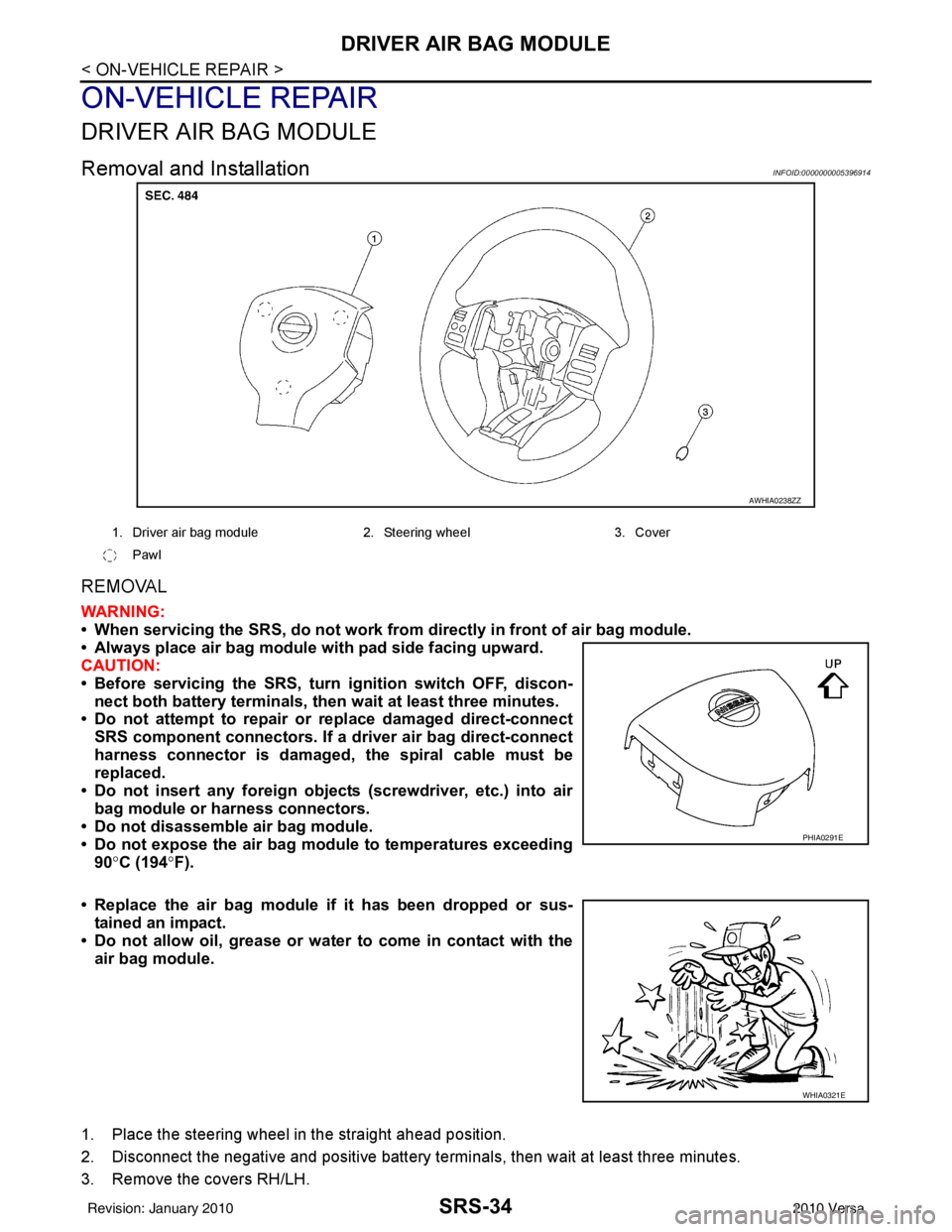
AWHIA0238ZZ
1. Driver air bag module 2. Steering wheel 3. Cover
Pawl
PHIA0291E
WHIA0321E
Revision: January 20102010 Versa
Page 3630 of 3745
SPIRAL CABLESRS-37
< ON-VEHICLE REPAIR >
C
DE
F
G
I
J
K L
M A
B
SRS
N
O P
SPIRAL CABLE
Removal and InstallationINFOID:0000000005396915
REMOVAL
WARNING:
When servicing the SRS, do not work from directly in front of air bag module.
CAUTION:
• Before servicing the SRS, turn ignition switch OFF, disconnect both battery terminals and wait at
least three minutes.
• Do not tap or bump the steering wheel.
• Do not disassemble the spiral cable.
• Do not allow oil, grease or water to co me in contact with the spiral cable.
• Replace the spiral cable if it has b een dropped or sustained an impact.
• With the steering linkage disconn ected, the spiral cable may snap by turning the steering wheel
beyond the limited number of turns. The spiral cable can be turned counterclockwise about 2.5 turns
from the neutral position.
1. Set the front wheels to the straight-ahead/neutral position.
2. Disconnect the negative and positive battery term inals, then wait at least three minutes.
3. Remove the steering wheel. Refer to PS-6
.
4. Remove the column cover upper and lower.
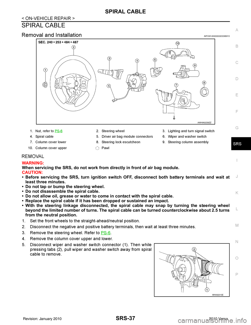
5. Disconnect wiper and washer switch connector (1). Then while pressing tabs (2), pull wiper and washer switch away from spiral
cable to remove.
AWHIA0239ZZ
1. Nut, refer to PS-62. Steering wheel 3. Lighting and turn signal switch
4. Spiral cable 5. Driver air bag module connectors 6. Wiper and washer switch
7. Column cover lower 8. Steering lock escutcheon 9. Steering column assembly
10. Column cover upper Pawl
WHIA0315E
Revision: January 20102010 Versa
Page 3635 of 3745
SRS-42
< ON-VEHICLE REPAIR >
CRASH ZONE SENSOR
CRASH ZONE SENSOR
Removal and InstallationINFOID:0000000005396919
REMOVAL
CAUTION:
• Before servicing the SRS, turn ignition switch OFF, disconnect both battery terminals and wait at
least three minutes.
• Do not disassemble the crash zone sensor.
• Do not use old nuts after removal; replace with new nuts.
• Replace the crash zone sensor if it has been dropped or sus- tained an impact.
• Check crash zone sensor to make sure it is free of deformi-
ties, dents, cracks or rust. If it shows any visible signs of dam-
age, replace it with a new one.
1. Disconnect both the negative and positive battery terminals, then wait at least three minutes.
2. Remove air intake duct. Refer to EM-26, "
Exploded View" (HR16DE), EM-135, "Component" (MR18DE).
3. Remove upper radiator cover and front grille, refer to EI-21
.
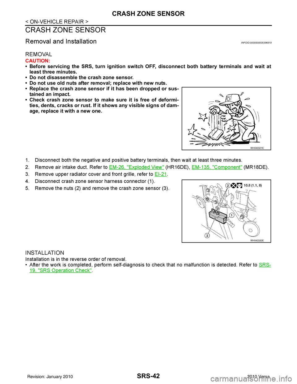
4. Disconnect crash zone sensor harness connector (1).
5. Remove the nuts (2) and remove the crash zone sensor (3).
INSTALLATION
Installation is in the reverse order of removal.
• After the work is completed, perform self-diagnosis to check that no malfunction is detected. Refer to SRS-
19, "SRS Operation Check".
WHIA0321E
WHIA0320E
Revision: January 20102010 Versa
Page 3636 of 3745
SIDE AIR BAG (SATELLITE) SENSORSRS-43
< ON-VEHICLE REPAIR >
C
DE
F
G
I
J
K L
M A
B
SRS
N
O P
SIDE AIR BAG (S ATELLITE) SENSOR
Removal and InstallationINFOID:0000000005396920
REMOVAL
WARNING:
Do not reuse center pillar upper garnish if removed.
CAUTION:
• Before servicing the SRS, turn ignition switch OFF, disconnect both battery terminals and wait at
least three minutes.
• Do not disassemble the side air bag (satellite) sensor.
• Do not use old nuts after removal; replace with new nuts.
• Replace the side air bag (satellite) sensor if it has been dropped or sustained an impact.
• Check side air bag (satellite) sensor to make sure it is free of deformities, dents, cracks or rust . If it shows any visible signs
of damage, replace it with a new one.
1. Disconnect both the negative and positive battery te rminals, then wait at least three minutes.
2. Remove the body side welt, kicking plate, and center pillar lower garnish. Refer to EI-39, "
Component".
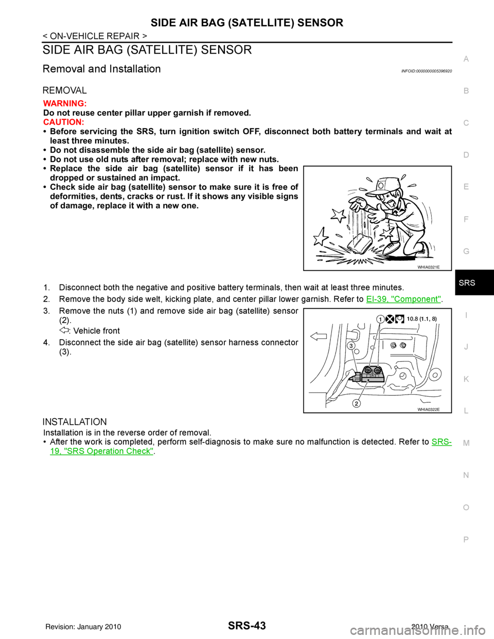
3. Remove the nuts (1) and remove side air bag (satellite) sensor (2).
: Vehicle front
4. Disconnect the side air bag (satellite) sensor harness connector (3).
INSTALLATION
Installation is in the reverse order of removal.
• After the work is completed, perform self-diagnosis to make sure no malfunction is detected. Refer to SRS-
19, "SRS Operation Check".
WHIA0321E
WHIA0322E
Revision: January 20102010 Versa
Page 3638 of 3745
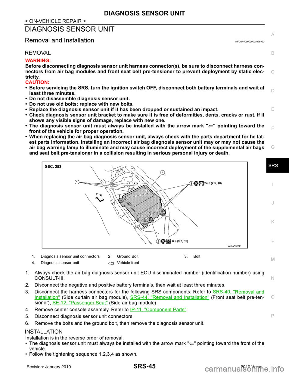
DIAGNOSIS SENSOR UNITSRS-45
< ON-VEHICLE REPAIR >
C
DE
F
G
I
J
K L
M A
B
SRS
N
O P
DIAGNOSIS SENSOR UNIT
Removal and InstallationINFOID:0000000005396922
REMOVAL
WARNING:
Before disconnecting diagnosis sensor unit harness connector(s), be sure to disconnect harness con-
nectors from air bag modules and front seat belt pre-tensioner to prevent deployment by static elec-
tricity.
CAUTION:
• Before servicing the SRS, turn th e ignition switch OFF, disconnect both battery terminals and wait at
least three minutes.
• Do not disassemble diagnosis sensor unit.
• Do not use old bolts; replace with new bolts.
• Replace the diagnosis sensor unit if it has been dropped or sustained an impact.
• Check diagnosis sensor unit bracket to make sure it is free of deformities, dents, cracks or rust. If it
shows any visible signs of da mage, replace with new one.
• The diagnosis sensor unit must always be installed with the arrow mark " ⇐" pointing toward the
front of the vehicle for proper operation.
• When replacing the air bag diagno sis sensor unit, always check with the parts department for he lat-
est parts information. Installing an incorrect air bag diagnosis sensor unit may or may not cause the
air bag warning lamp to illuminate and may cause incorrect deployment of the supplemental air bags
and seat belt pre-tensioner in a collision r esulting in serious personal injury or death.
1. Always check the air bag diagnosis sensor unit E CU discriminated number (identification number) using
CONSULT-III.
2. Disconnect the negative and positive battery term inals, then wait at least three minutes.
3. Disconnect the harness connectors for the following SRS components: Refer to SRS-40, "
Removal and
Installation" (Side curtain air bag module), SRS-44, "Removal and Installation" (Front seat belt pre-ten-
sioner), SE-12, "
Passenger Seat" (Side air bag module).
4. Remove center console assembly. Refer to IP-11, "
Component Parts".
5. Disconnect diagnosis sensor unit connectors.
6. Remove the bolts and the ground bolt, then remove the diagnosis sensor unit.
INSTALLATION
Installation is in the reverse order of removal.
• The diagnosis sensor unit must always be installed with the arrow mark " ⇐" pointing toward the front of the
vehicle.
• Follow the tightening sequence 1,2,3,4 as shown.
1. Diagnosis sensor unit connectors 2. Ground Bolt 3. Bolt
4. Diagnosis sensor unit Vehicle front
WHIA0323E
Revision: January 20102010 Versa
Page 3654 of 3745
![NISSAN TIIDA 2010 Service Repair Manual STC-8
< SYSTEM DESCRIPTION >[EPS]
DIAGNOSIS SYSTEM (EPS CONTROL UNIT)
DIAGNOSIS SYSTEM
(EPS CONTROL UNIT)
CONSULT-III FunctionINFOID:0000000005600160
FUNCTION
CONSULT-III can display each diagnostic NISSAN TIIDA 2010 Service Repair Manual STC-8
< SYSTEM DESCRIPTION >[EPS]
DIAGNOSIS SYSTEM (EPS CONTROL UNIT)
DIAGNOSIS SYSTEM
(EPS CONTROL UNIT)
CONSULT-III FunctionINFOID:0000000005600160
FUNCTION
CONSULT-III can display each diagnostic](/manual-img/5/57397/w960_57397-3653.png)
STC-8
< SYSTEM DESCRIPTION >[EPS]
DIAGNOSIS SYSTEM (EPS CONTROL UNIT)
DIAGNOSIS SYSTEM
(EPS CONTROL UNIT)
CONSULT-III FunctionINFOID:0000000005600160
FUNCTION
CONSULT-III can display each diagnostic item us ing the diagnostic test modes shown following.
ECU IDENTIFICATION
Displays the part number stored in the control unit.
SELF-DIAG RESULTS MODE
Display Item List
Refer to STC-24, "DTC Index".
CAUTION:
If “CAN COMM CIRCUIT [U1000]” is disp layed with other DTCs, first perform the trouble diagnosis for
CAN communication line.
DATA MONITOR MODE
Display Item List
*1: Almost in accordance with the value of MOTOR SIG. It is not a malfunction though these values are not accorded when steerin g
quickly.
*2: It is not a malfunction, though it might not be corresponding just after ignition switch in turned ON. Diagnostic test mode
Function
ECU identification Steering column assembly number can be read.
Self diagnostic result Self-diagnostic results can be read and erased quickly.
Data monitor Input/Output data in the EPS control unit can be read.
Monitor item (Unit) Remarks
MOTOR VOL (V) Displays the power supply voltage for EPS control unit.
TORQUE SENSOR (Nm) Displays steering wheel turning force detected by torque sensor.
MOTOR CURRENT (A) Displays the current value consumed by EPS motor.
MOTOR SIG (A)
*1Displays the current commanded value to EPS motor.
DERATING STAT (ON/OFF%) Protect overload status is displayed.
VEHICLE SPEED (km/h) or (MPH)
*2Vehicle speed is displayed from vehicle speed signal via CAN communication.
WARNING LAMP (On/Off) EPS warning lamp control status is displayed.
ENGINE STATUS (Stop/Run) Engine speed is displayed from engine status signal via CAN communication.
Revision: January 20102010 Versa
Page 3655 of 3745
![NISSAN TIIDA 2010 Service Repair Manual C1601 BATTERY POWER SUPPLYSTC-9
< DTC/CIRCUIT DIAGNOSIS > [EPS]
C
D
E
F
H I
J
K L
M A
B
STC
N
O P
DTC/CIRCUIT DIAGNOSIS
C1601 BATTERY POWER SUPPLY
DescriptionINFOID:0000000005600161
Power is supplied NISSAN TIIDA 2010 Service Repair Manual C1601 BATTERY POWER SUPPLYSTC-9
< DTC/CIRCUIT DIAGNOSIS > [EPS]
C
D
E
F
H I
J
K L
M A
B
STC
N
O P
DTC/CIRCUIT DIAGNOSIS
C1601 BATTERY POWER SUPPLY
DescriptionINFOID:0000000005600161
Power is supplied](/manual-img/5/57397/w960_57397-3654.png)
C1601 BATTERY POWER SUPPLYSTC-9
< DTC/CIRCUIT DIAGNOSIS > [EPS]
C
D
E
F
H I
J
K L
M A
B
STC
N
O P
DTC/CIRCUIT DIAGNOSIS
C1601 BATTERY POWER SUPPLY
DescriptionINFOID:0000000005600161
Power is supplied from the battery to EPS control unit.
DTC LogicINFOID:0000000005600162
DTC DETECTION LOGIC
DTC CONFIRMATION PROCEDURE
1.DTC REPRODUCTION PROCEDURE
With CONSULT-III
1. Turn the ignition switch OFF to ON.
2. Perform EPS control unit self-diagnosis.
Is DTC
“C1601” detected?
YES >> Proceed to diagnosis procedure. Refer to STC-9, "Diagnosis Procedure".
NO >> Inspection End.
Diagnosis ProcedureINFOID:0000000005600163
1.CHECK EPS CONTROL UNIT GROUND CIRCUIT
1. Turn ignition switch OFF.
2. Disconnect EPS control unit harness connector.
3. Check continuity between EPS control unit harness connector terminal and ground.
4. Connect EPS control unit harness connector.
Is the inspection result normal?
YES >> GO TO 2.
NO >> Repair open circuit or short to ground or short to power in harness or connectors.
2.CHECK EPS CONTROL UNI T POWER SUPPLY CIRCUIT
1. Check voltage between EPS control unit harness connector terminals and ground.
2. Turn ignition switch ON. CAUTION:
Never start the engine.
3. Check voltage between EPS control unit harness connector terminals and ground.
DTC Display item Malfunction detected condition Possible cause
C1601 BATTERY VOLT When a power supp
ly voltage to the EPS control unit
is maintained at or above 17.5 V or less than 9 V con-
tinuously for more than five seconds. • Harness or connector
• EPS control unit
EPS control unit
—Con tin uit y
Connector Terminal
M54 18Ground Existed
EPS control unit
—Volt a g e
Connector Terminal
M53 10
Ground Approx. 0 V
M54 17 Battery voltage
Revision: January 20102010 Versa
Page 3656 of 3745
![NISSAN TIIDA 2010 Service Repair Manual STC-10
< DTC/CIRCUIT DIAGNOSIS >[EPS]
C1601 BATTERY POWER SUPPLY
Is the inspection result normal?
YES >> GO TO 3.
NO >> Check the following. If any items are damaged, repair or replace damaged parts.
NISSAN TIIDA 2010 Service Repair Manual STC-10
< DTC/CIRCUIT DIAGNOSIS >[EPS]
C1601 BATTERY POWER SUPPLY
Is the inspection result normal?
YES >> GO TO 3.
NO >> Check the following. If any items are damaged, repair or replace damaged parts.](/manual-img/5/57397/w960_57397-3655.png)
STC-10
< DTC/CIRCUIT DIAGNOSIS >[EPS]
C1601 BATTERY POWER SUPPLY
Is the inspection result normal?
YES >> GO TO 3.
NO >> Check the following. If any items are damaged, repair or replace damaged parts.
• 10A fuse (#2) open
- Harness for short between 10A fuse (#2) and pow er steering control unit harness connector No.
10 terminal.
• 60A fusible link (M) open
- Harness for short between 60A fusible link (M) and power steering control unit harness connec-
tor No. 10 terminal.
• Harness for open between ignition switch and power steering control unit harness connector No. 17 terminal.
• Harness for open between battery and power steering control unit harness connector No. 17 ter-
minal.
• Battery or ignition switch.
3.CHECK BATTERY VOLTAGE SIGNAL (1)
With CONSULT-III
1. Connect EPS control unit harness connector.
2. Start the engine. CAUTION:
Stop the vehicle.
3. Select “EPS”, “DATA MONITOR” and “MOTOR VO LT”, and perform the battery voltage inspection.
Is the inspection result normal?
YES >> GO TO 4.
NO >> Replace EPS control unit. Refer to PS-9, "
Removal and Installation".
4.CHECK MOTOR VOLTAGE SIGNAL (2)
With CONSULT-III
Select “MOTOR VOLT” in “DATA MONITOR” of the EPS control unit. Check motor voltage with the steering
wheel fully turned leftward or rightward.
Is the value in
“DATA MONITOR”“between 9 V and 17.5 V”?
YES >> Check pin terminal and connection of each harness connector for damage or loose connection.
NO >> Check battery power supply and ignition power supply. Refer to STC-22, "
Wiring Diagram - ELEC-
TRONICALLY CONTROLLED POWER STEERING SYSTEM -".
EPS control unit
—Volt a ge
Connector Terminal
M53 10
Ground Battery voltage
M54 17
Monitor item ConditionDisplay value
MOTOR VOLT Engine runningBattery voltage
Revision: January 20102010 Versa