2010 NISSAN TIIDA ignition
[x] Cancel search: ignitionPage 3596 of 3745

PRECAUTIONSSRS-3
< PRECAUTION >
C
DE
F
G
I
J
K L
M A
B
SRS
N
O P
• Always use CONSULT-III to perform self-diagnosis as a part of each function inspection after finishing work.
If DTC is detected, perform trouble diagnosis according to self-diagnostic results.
For models equipped with the Intelligent Key system and NATS , an electrically controlled steering lock mech-
anism is adopted on the key cylinder.
For this reason, if the battery is disconnected or if the battery is discharged, the steering wheel will lock and
steering wheel rotation will become impossible.
If steering wheel rotation is required when battery power is interrupted, follow the procedure below before
starting the repair operation.
OPERATION PROCEDURE
1. Connect both battery cables. NOTE:
Supply power using jumper cables if battery is discharged.
2. Use the Intelligent Key or mechanical key to turn the ignition switch to the ″ACC ″ position. At this time, the
steering lock will be released.
3. Disconnect both battery cables. The steering lock will remain released and the steering wheel can be
rotated.
4. Perform the necessary repair operation.
5. When the repair work is completed, return the ignition switch to the ″LOCK ″ position before connecting
the battery cables. (At this time, the steering lock mechanism will engage.)
6. Perform a self-diagnosis check of al l control units using CONSULT-III.
Occupant Classification System PrecautionINFOID:0000000005396894
Replace control unit and passenger front seat cushion as an assembly.
Revision: January 20102010 Versa
Page 3597 of 3745

SRS-4
< SYMPTOM DIAGNOSIS >
SUPPLEMENTAL RESTRAINT SYSTEM (SRS)
SYMPTOM DIAGNOSIS
SUPPLEMENTAL RESTRAINT SYSTEM (SRS)
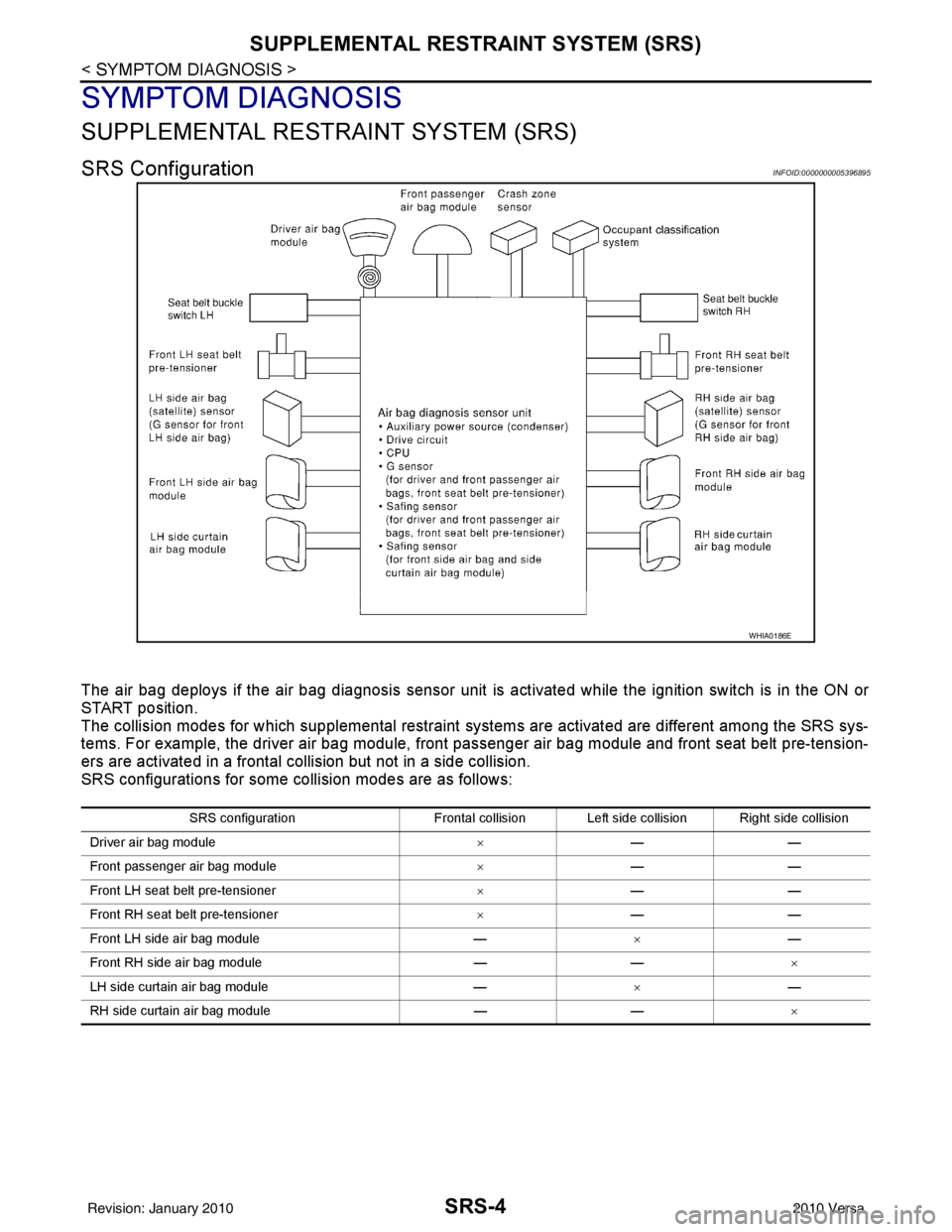
SRS ConfigurationINFOID:0000000005396895
The air bag deploys if the air bag diagnosis sensor unit is activated while the ignition switch is in the ON or
START position.
The collision modes for which supplemental restraint systems are activated are different among the SRS sys-
tems. For example, the driver air bag module, front passenger air bag module and front seat belt pre-tension-
ers are activated in a frontal collision but not in a side collision.
SRS configurations for some collision modes are as follows:
WHIA0186E
SRS configuration Frontal collision Left side collision Right side collision
Driver air bag module ×——
Front passenger air bag module ×——
Front LH seat belt pre-tensioner ×——
Front RH seat belt pre-tensioner ×——
Front LH side air bag module —×—
Front RH side air bag module —— ×
LH side curtain air bag module —×—
RH side curtain air bag module —— ×
Revision: January 20102010 Versa
Page 3612 of 3745

TROUBLE DIAGNOSISSRS-19
< SYMPTOM DIAGNOSIS >
C
DE
F
G
I
J
K L
M A
B
SRS
N
O P
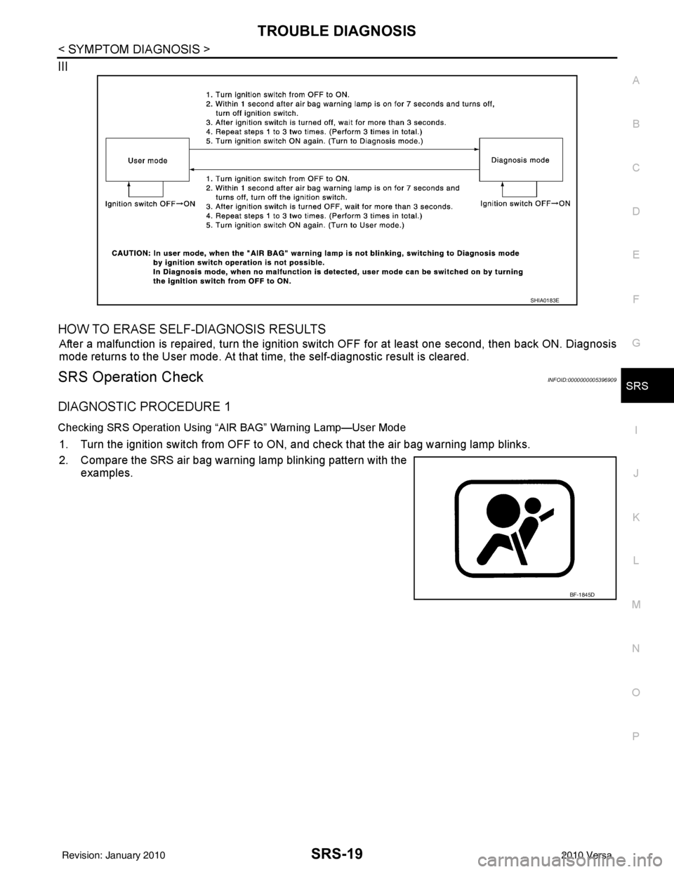
III
HOW TO ERASE SELF-DIAGNOSIS RESULTS
After a malfunction is repaired, turn the ignition switch OFF for at least one second, then back ON. Diagnosis
mode returns to the User mode. At that time, the self-diagnostic result is cleared.
SRS Operation CheckINFOID:0000000005396909
DIAGNOSTIC PROCEDURE 1
Checking SRS Operation Using “AIR BAG” Warning Lamp—User Mode
1. Turn the ignition switch from OFF to ON, and check that the air bag warning lamp blinks.
2. Compare the SRS air bag warning lamp blinking pattern with the
examples.
SHIA0183E
BF-1845D
Revision: January 20102010 Versa
Page 3617 of 3745

SRS-24
< SYMPTOM DIAGNOSIS >
TROUBLE DIAGNOSIS
NOTE:
Follow the procedures in numerical order when performing repairs. Confirm whether the repair has been suc-
cessful using air bag warning lamp or CONSULT-III after each repair. If malfunction is still observed, proceed
to the next step. When malfunction has been elimi nated, further repair work is not required.
DIAGNOSTIC PROCEDURE 3
Final Check of SRS Using CONSULT-III—Diagnosis Mode
1. If no DTC is detected on “SELF-DIAG [CURRENT]”, repair of SRS is completed. Go to step 2.
If any DTC is detected on “SELF-DIAG [CURRENT]” , the malfunctioning part has not been repaired com-
pletely or another malfunctioning part is being detected. Go to "DIAGNOSTIC PROCEDURE 2".
2. Touch “ERASE”. NOTE:
Touch “ERASE” to clear the memory of the malfunction (“SELF-DIAG [PAST]”).
If the memory of the malfunction in “SELF-DIAG [P AST]” is not erased, the User mode shows the system
malfunction by the operation of the warning lamp even if the malfunction is repaired completely.
3. Touch “BACK” key of CONSULT-III to “SELECT DIAG MODE” screen. Touch “SELF-DIAG [PAST]”.
4. Check that no malfunction is detected on “SELF-DIAG [PAST]”.
5. Touch “BACK” key of CONSULT-III until “SELECT SY STEM” appears in order to return to User mode from
Diagnosis mode.
6. Turn ignition switch OFF then turn off and disconnect CONSULT-III.
7. Go to SRS-19, "
SRS Operation Check".
DIAGNOSTIC PROCEDURE 4
Check SRS Repair History
1.CONSIDER POSSIBILITY THAT SELF-DIAGNOSTIC RESULT WAS NOT ERASED AFTER REPAIR
Check repair history of the SRS.
Have any previous repairs been made to the SRS?
Yes >> Self-diagnostic result “SELF-DIAG [PAST]” (pre viously stored in the memory) might not be erased
after repair. Go to "DIAGNOSTIC PROCEDURE 3".
No >> Go to "DIAGNOSTIC PROCEDURE 2".
DIAGNOSTIC PROCEDURE 5
Check SRS Intermittent Malfuncti on Using CONSULT-III—Diagnosis Mode
1. If diagnostic codes are displayed on “SELF-DIAG [PAST]”, go to step 4.
If no malfunction is detected on “SELF-DIAG [PAS T]”, touch “BACK” and go back to “SELECT DIAG
MODE”.
BELT TENSION SENS
[UNIT FAIL]
[B1019] Belt tension sensor is malfunctioning.
1. Visually check the wiring harness
connection.
2. Replace the harness if it has visi- ble damage.
3. Replace the RH front seat belt as- sembly.
4. Replace the RH front seat cush-
ion assembly. Do not disassem-
ble the seat cushion assembly.
5. Replace the related harness.
FRONTAL COLLISION DETECTION[B1209] Driver and front passenger air bag modules are deployed. Refer to
SRS-48
.
SIDE COLLISION DETECTION
[B1210] Side or curtain air bag modules are deployed.
Diagnostic item
Explanation Repair order
Recheck SRS at each replacement
Revision: January 20102010 Versa
Page 3618 of 3745

TROUBLE DIAGNOSISSRS-25
< SYMPTOM DIAGNOSIS >
C
DE
F
G
I
J
K L
M A
B
SRS
N
O P
2. Touch “TROUBLE DIAG RECORD”. NOTE:
With “TROUBLE DIAG RECORD”, di agnosis results previously erased by a reset operation can be
displayed.
3. Diagnostic code is displayed on “TROUBLE DIAG RECORD”.
4. Touch “PRINT”.
5. Compare diagnostic codes to "CONSULT-III Diagnos tic Code Chart ("SELF-DIAG [PAST]" or "TROUBLE
DIAG RECORD")".
6. Touch “BACK” key of CONSULT- III until “SELECT SYSTEM” appears.
7. Turn ignition switch OFF, then turn off and disconnect CONSULT-III, and both battery cables.
8. Repair the system as outlined by the “Repair orde r” in “Intermittent Malfunction Diagnostic Code Chart”,
that corresponds to the self-diagnostic result. For r eplacement procedure of component parts, refer to the
Removal and Installation procedure for the appropriate component.
9. Go to "DIAGNOSTIC PROCEDURE 3", for final checking.
CONSULT-III Diagnostic Code Chart ("SELF-DI AG [PAST]" or "TROUBLE DIAG RECORD")
Diagnostic item Explanation Repair order
Recheck SRS at each replacement
NO DTC IS DETECTED When malfunction is
indicated by the “AIR
BAG” warning lamp in
User mode.
• Low battery voltage (L
ess than 9V) • Go to "DIAGNOSTIC PROCEDURE
3" .
• Self-diagnostic result “SELF-DIAG [PAST]” (previously stored in the
memory) might not be erased after
repair.
• Intermittent malfunction has been detected in the past. • Go to "DIAGNOSTIC PROCEDURE
4" .
• Go to "DIAGNOSTIC PROCEDURE
5" .
• No malfunction is detected. —
DRIVER AIRBAG MODULE [OPEN]
[B1049] or [B1054] Driver air bag module circuit is open (including the spiral ca-
ble).
1. Visually check the wiring harness
connection.
2. Replace the harness if it has visi- ble damage.
3. Replace driver air bag module.
4. Replace the spiral cable.
5. Replace the air bag diagnosis sensor unit.
6. Replace the related harness.
DRIVER AIRBAG MODULE
[VB-SHORT]
[B1050] or [B1055] Driver air bag module circuit is shorted to some power supply
circuit (including the spiral cable).
DRIVER AIRBAG MODULE [GND-SHORT]
[B1051] or [B1056] Driver air bag module circuit is shorted to ground (including
the spiral cable).
DRIVER AIRBAG MODULE [SHORT]
[B1052] or [B1057] Driver air bag module circuits are shorted to each other.
ASSIST A/B MODULE [OPEN]
[B1065] or [B1070] Front passenger air bag module circuit is open.
1. Visually check the wiring harness
connection.
2. Replace the harness if it has visi-
ble damage.
3. Replace front passenger air bag module.
4. Replace the air bag diagnosis sensor unit.
5. Replace the related harness.
ASSIST A/B MODULE
[VB-SHORT]
[B1066] or [B1071] Front passenger air bag module circuit is shorted to some
power supply circuit.
ASSIST A/B MODULE [GND-SHORT]
[B1067] or [B1072] Front passenger air bag module circuit is shorted to ground.
ASSIST A/B MODULE [SHORT]
[B1068] or [B1073] Front passenger air bag module circuits are shorted to each
other.
Revision: January 20102010 Versa
Page 3621 of 3745

SRS-28
< SYMPTOM DIAGNOSIS >
TROUBLE DIAGNOSIS
NOTE:
Follow the procedures in numerical order when performing repairs. Confirm whether the repair has been suc-
cessful using air bag warning lamp or CONSULT-III after each repair. If malfunction is still observed, proceed
to the next step. When malfunction has been elimi nated, further repair work is not required.
Trouble Diagnosis without CONSULT-IIIINFOID:0000000005396911
DIAGNOSTIC PROCEDURE 6
Inspect SRS Malfunction Using "AIR BAG" Warning Lamp—Diagnosis Mode
NOTE:
SRS will not enter Diagnosis mode if no malfunction is detected in User mode.
1. Turn ignition switch ON.
2. After “AIR BAG” warning lamp lights for 7 seconds, turn ignition switch OFF within 1 second.
3. Wait more than 3 seconds.
4. Repeat steps 1 to 3 two times.
5. Turn ignition switch ON.
SRS is now in Diagnosis mode.
"AIR BAG" warning lamp operates in Diagnosis mode according to the Warning Lamp Flash Code Chart:
OCCUPANT SENS C/U [COMM FAIL]
[B1022] Communication between the occupant classification system
control unit and air bag diagnosis sensor unit is interrupted.
1. Visually check the wiring harness
connection.
2. Replace the harness if it has visi- ble damage.
3. Replace RH front seat cushion/ occupant classification system
control unit assembly.
4. Replace the air bag diagnosis sensor unit.
5. Replace the related harness.
OCCUPANT SENS [UNIT FAIL][B1018] Occupant classification sensor is malfunctioning.
1. Replace RH front seat cushion/
occupant classification system
control unit assembly.
BELT TENSION SENS [UNIT FAIL]
[B1019] Belt tension sensor is malfunctioning.
1. Visually check the wiring harness
connection.
2. Replace the harness if it has visi- ble damage.
3. Replace RH front seat belt as-
sembly.
4. Replace RH front seat cushion/ occupant classification system
control unit assembly.
PASS A/B INDCTR CKT [B1023] Front passenger air bag off indicator is malfunctioning. 1. Visually check the wiring harness
connection.
2. Replace the harness if it has visi-
ble damage.
3. Replace front passenger air bag off indicator.
4. Replace the air bag diagnosis sensor unit.
5. Replace the related harness.
FRONTAL COLLISION DETECTION[B1209] Driver and front passenger air bag modules are deployed. Refer to
SRS-48
.
SIDE COLLISION DETECTION
[B1210] Side or curtain air bag modules are deployed.
Diagnostic item
Explanation Repair order
Recheck SRS at each replacement
Revision: January 20102010 Versa
Page 3625 of 3745

SRS-32
< SYMPTOM DIAGNOSIS >
TROUBLE DIAGNOSIS
1.CHECK CONDITION OF AIR BAG MODULE
Inspect for any deployed air bag modules or seat belt pre-tensioners.
Are any air bag modules or s eat belt pre-tensioners deployed?
Yes >> Refer to SRS-48.
No >> GO TO 2.
2.CHECK THE AIR BAG FUSE
Check 10A fuse [No. 1, locat ed in the fuse block (J/B)].
Refer to PG-4
.
OK or NG
OK >> GO TO 4.
NG >> GO TO 3.
3.CHECK AIR BAG FUSE AGAIN
Replace 10A fuse [No. 1, located in the fu se block (J/B)] and turn ignition switch ON.
Does the fuse blow again?
Yes >> Repair harness.
No >> Inspection End.
4.CHECK AIR BAG DIAGNOSIS SENSOR UNIT
Connect CONSULT-III and touch “START”.
Is
“AIR BAG” displayed on CONSULT-III?
Ye s > > G O T O 5 .
No >> Visually inspect the air bag diagnosis sensor unit harness connections. If the connections are OK,
replace the air bag diagnosis sensor unit. Refer to SRS-45, "
Removal and Installation".
5.CHECK HARNESS CONNECTION
Check for loose connections between the combination meter and the air bag diagnosis sensor unit.
OK or NG
OK >> Replace air bag diagnosis sensor unit. Refer to SRS-45, "Removal and Installation".
NG >> Properly connect the combination meter and ai r bag diagnosis sensor unit harness connectors. If
“AIR BAG” warning lamp still does not turn off, replace the wiring harness.
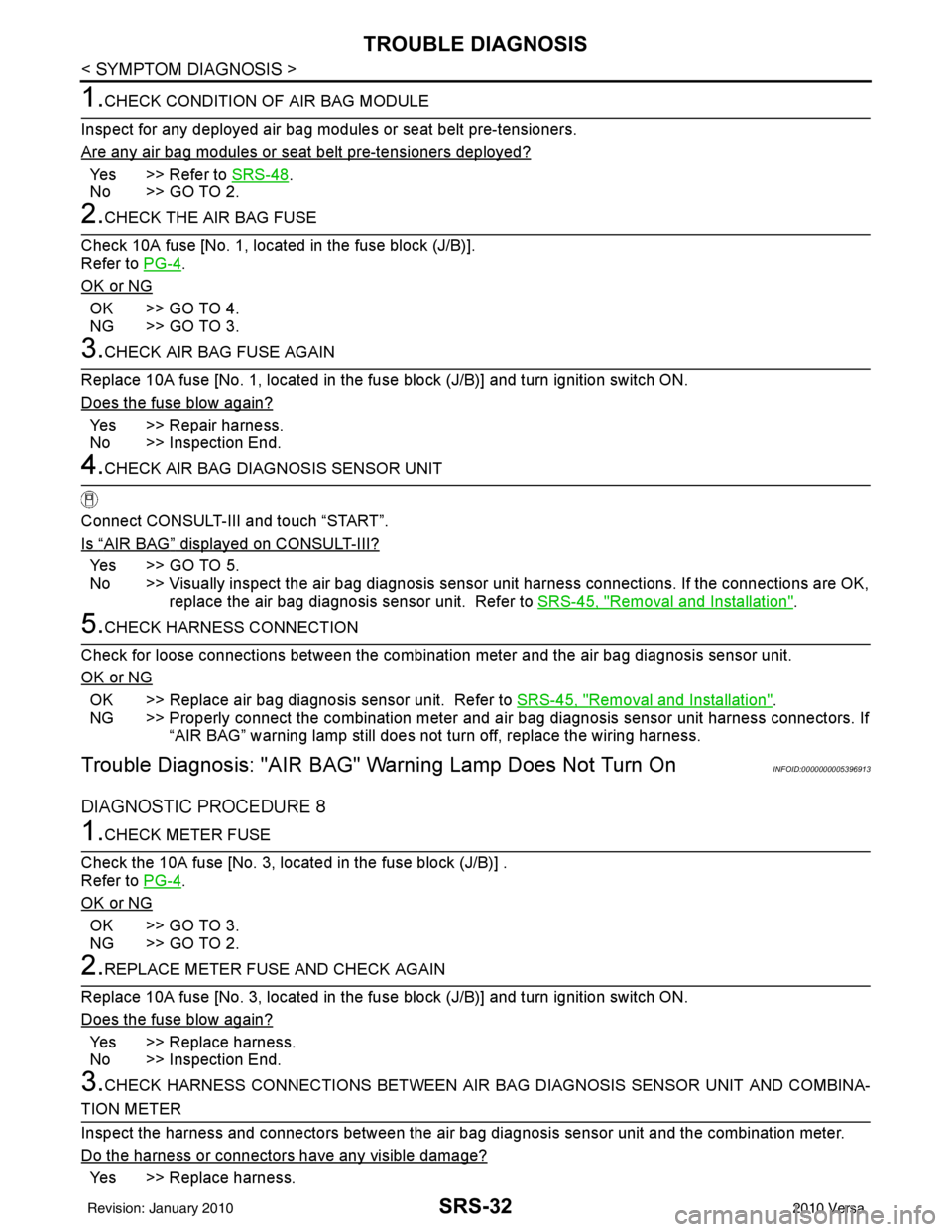
Trouble Diagnosis: "AIR BAG" Warning Lamp Does Not Turn OnINFOID:0000000005396913
DIAGNOSTIC PROCEDURE 8
1.CHECK METER FUSE
Check the 10A fuse [No. 3, located in the fuse block (J/B)] .
Refer to PG-4
.
OK or NG
OK >> GO TO 3.
NG >> GO TO 2.
2.REPLACE METER FUSE AND CHECK AGAIN
Replace 10A fuse [No. 3, located in the fu se block (J/B)] and turn ignition switch ON.
Does the fuse blow again?
Yes >> Replace harness.
No >> Inspection End.
3.CHECK HARNESS CONNECTIONS BET WEEN AIR BAG DIAGNOSIS SENSOR UNIT AND COMBINA-
TION METER
Inspect the harness and connectors between the air bag diagnosis sensor unit and the combination meter.
Do the harness or connectors have any visible damage?
Yes >> Replace harness.
Revision: January 20102010 Versa
Page 3626 of 3745

TROUBLE DIAGNOSISSRS-33
< SYMPTOM DIAGNOSIS >
C
DE
F
G
I
J
K L
M A
B
SRS
N
O P
No >> GO TO 4.
4.CHECK COMBINATION METER
Disconnect the air bag diagnosis sensor unit harnes s connectors and turn ignition switch ON.
Does
“AIR BAG” warning lamp turn on?
Yes >> Replace the air bag diagnosis sensor unit. Refer to SRS-45, "Removal and Installation".
No >> Replace the combination meter. Refer to IP-12, "
Removal and Installation".
Revision: January 20102010 Versa