2010 NISSAN TIIDA coolant temperature
[x] Cancel search: coolant temperaturePage 2836 of 3745
![NISSAN TIIDA 2010 Service Repair Manual CAN COMMUNICATION SYSTEMLAN-27
< SERVICE INFORMATION > [CAN]
C
D
E
F
G H
I
J
L
M A
B
LAN
N
O P
CAN Communication Signal ChartINFOID:0000000005395135
Refer to LAN-16, "How to Use CAN Communication Sig NISSAN TIIDA 2010 Service Repair Manual CAN COMMUNICATION SYSTEMLAN-27
< SERVICE INFORMATION > [CAN]
C
D
E
F
G H
I
J
L
M A
B
LAN
N
O P
CAN Communication Signal ChartINFOID:0000000005395135
Refer to LAN-16, "How to Use CAN Communication Sig](/manual-img/5/57397/w960_57397-2835.png)
CAN COMMUNICATION SYSTEMLAN-27
< SERVICE INFORMATION > [CAN]
C
D
E
F
G H
I
J
L
M A
B
LAN
N
O P
CAN Communication Signal ChartINFOID:0000000005395135
Refer to LAN-16, "How to Use CAN Communication Signal Chart" for how to use CAN communication signal
chart.
NOTE:
Refer to LAN-22, "
Abbreviation List" for the abbreviations of the connecting units.
T: Transmit R: Receive
Signal name/Connecting unitECM
BCM
EPS
I-KEY M&A
STRG ABS
TCM
*1
TCM
*2
IPDM-E
A/C compressor request signal T R
Accelerator pedal position signal T
R
*3RR
ASCD CRUISE lamp signal T R
ASCD SET lamp signal T R
Closed throttle position signal T R R
Cooling fan motor operation signal T R
Engine coolant temperature signal TR
Engine speed signal TR
R
*3R
Engine status signal T R R R
Fuel consumption monitor signal T R
Malfunction indicator lamp signal TR
Wide open throttle position signal T R R
A/C switch signal R T
Blower fan motor switch signal R T
Buzzer output signal TR
TR
Day time running light request signal
*4TR
Door lock/unlock status signal TR
Door switch signal TR R R
Front wiper request signal T R
High beam request signal TR R
Horn chirp signal T R
Ignition switch signal T R
Low beam request signal T R
Position lights request signal TR R
Rear window defogger switch signal T R
Sleep/wake up signal TRR
R
RT
Theft warning horn request signal T R
Tire pressure signal
*5TR
Trunk open/close status signal TR
Turn indicator signal TR
EPS operation signal TR
EPS warning lamp signal TR
Door lock/unlock/trunk open request signal RT
Hazard request signal RT
Ignition knob switch signal RT
Revision: January 20102010 Versa
Page 3143 of 3745
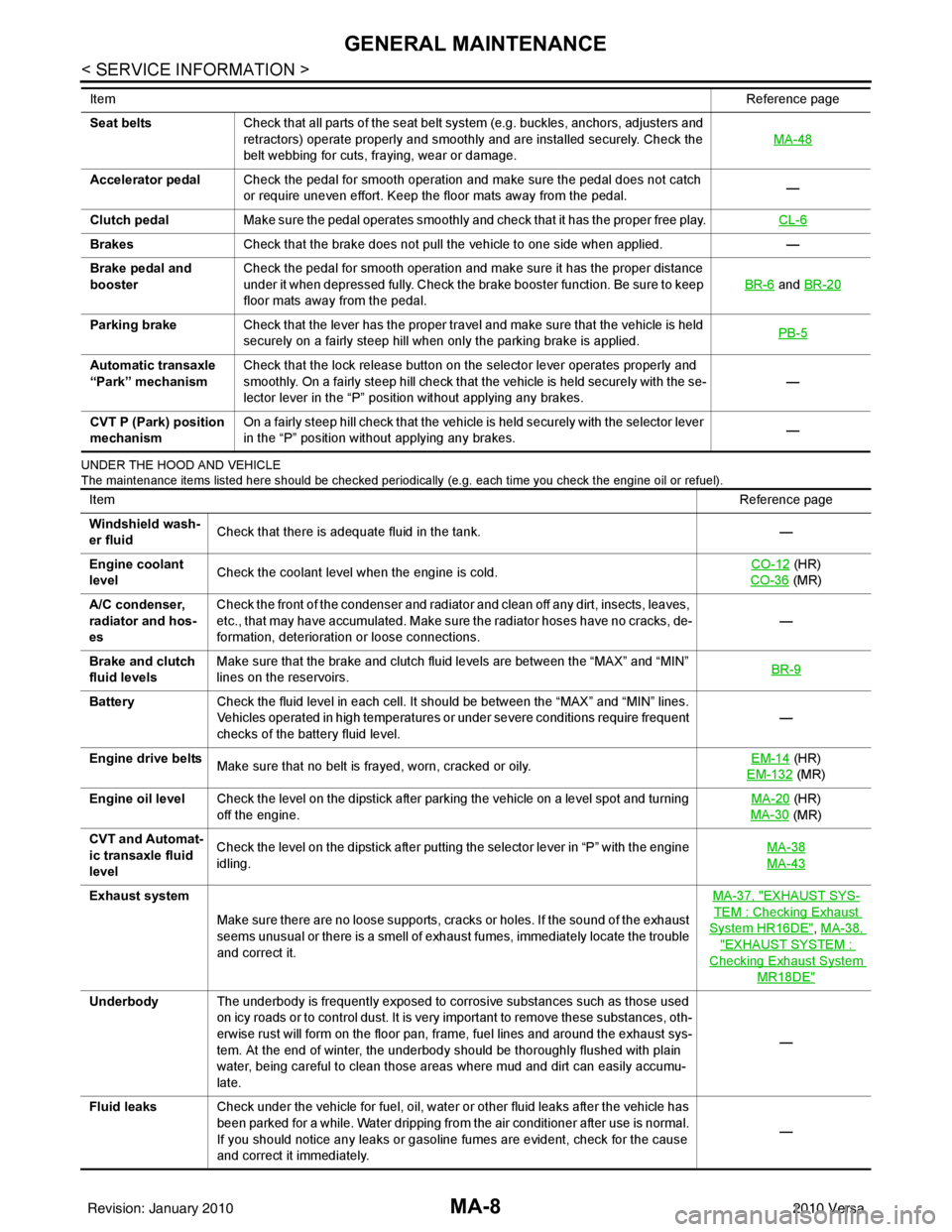
MA-8
< SERVICE INFORMATION >
GENERAL MAINTENANCE
UNDER THE HOOD AND VEHICLE
The maintenance items listed here should be checked periodically (e.g. each time you check the engine oil or refuel).
Seat beltsCheck that all parts of the seat belt system (e.g. buckles, anchors, adjusters and
retractors) operate properly and smoothly and are installed securely. Check the
belt webbing for cuts, fraying, wear or damage. MA-48
Accelerator pedal
Check the pedal for smooth operation and make sure the pedal does not catch
or require uneven effort. Keep the floor mats away from the pedal. —
Clutch pedal Make sure the pedal operates smoothly and check that it has the proper free play. CL-6
BrakesCheck that the brake does not pull the vehicle to one side when applied. —
Brake pedal and
booster Check the pedal for smooth operation and make sure it has the proper distance
under it when depressed fully. Check the brake booster function. Be sure to keep
floor mats away from the pedal. BR-6
and
BR-20
Parking brake Check that the lever has the proper travel and make sure that the vehicle is held
securely on a fairly steep hill when only the parking brake is applied. PB-5
Automatic transaxle
“Park” mechanismCheck that the lock release button on the selector lever operates properly and
smoothly. On a fairly steep hill check that the vehicle is held securely with the se-
lector lever in the “P” position without applying any brakes. —
CVT P (Park) position
mechanism On a fairly steep hill check that the vehicle is held securely with the selector lever
in the “P” position without applying any brakes.
—
Item
Reference page
ItemReference page
Windshield wash-
er fluid Check that there is adequate fluid in the tank.
—
Engine coolant
level Check the coolant level when the engine is cold. CO-12
(HR)
CO-36
(MR)
A/C condenser,
radiator and hos-
es Check the front of the condenser and radiator and clean off any dirt, insects, leaves,
etc., that may have accumulated. Make sure the radiator hoses have no cracks, de-
formation, deterioration or loose connections.
—
Brake and clutch
fluid levels Make sure that the brake and clutch fluid levels are between the “MAX” and “MIN”
lines on the reservoirs.
BR-9
Battery
Check the fluid level in each cell. It should be between the “MAX” and “MIN” lines.
Vehicles operated in high temperatures or under severe conditions require frequent
checks of the battery fluid level. —
Engine drive belts Make sure that no belt is frayed, worn, cracked or oily. EM-14
(HR)
EM-132
(MR)
Engine oil level Check the level on the dipstick after parking the vehicle on a level spot and turning
off the engine. MA-20
(HR)
MA-30
(MR)
CVT and Automat-
ic transaxle fluid
level Check the level on the dipstick after putting the selector lever in “P” with the engine
idling.
MA-38
MA-43
Exhaust system
Make sure there are no loose supports, cracks or holes. If the sound of the exhaust
seems unusual or there is a smell of exhaust fumes, immediately locate the trouble
and correct it. MA-37, "EXHAUST SYS-
TEM : Checking Exhaust
System HR16DE", MA-38,
"EXHAUST SYSTEM :
Checking Exhaust System
MR18DE"
Underbody
The underbody is frequently exposed to corrosive substances such as those used
on icy roads or to control dust. It is very important to remove these substances, oth-
erwise rust will form on the floor pan, frame, fuel lines and around the exhaust sys-
tem. At the end of winter, the underbody should be thoroughly flushed with plain
water, being careful to clean those areas where mud and dirt can easily accumu-
late. —
Fluid leaks Check under the vehicle for fuel, oil, water or other fluid leaks after the vehicle has
been parked for a while. Water dripping from the air conditioner after use is normal.
If you should notice any leaks or gasoline fumes are evident, check for the cause
and correct it immediately. —
Revision: January 20102010 Versa
Page 3144 of 3745
PERIODIC MAINTENANCEMA-9
< SERVICE INFORMATION >
C
DE
F
G H
I
J
K
M A
B
MA
N
O P
PERIODIC MAINTENANCE
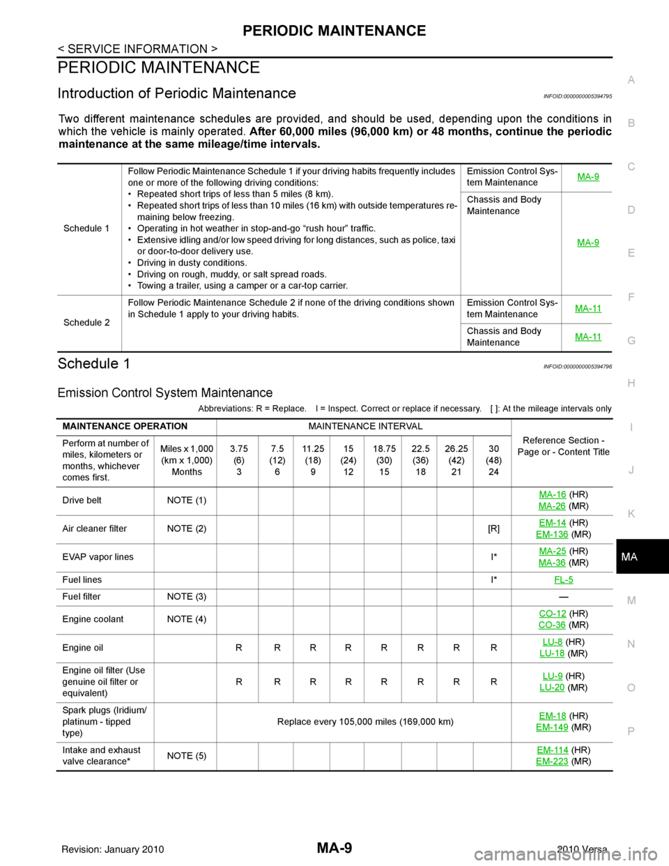
Introduction of Periodic MaintenanceINFOID:0000000005394795
Two different maintenance schedules are provi ded, and should be used, depending upon the conditions in
which the vehicle is mainly operated. After 60,000 miles (96,000 km) or 48 months, continue the periodic
maintenance at the same mileage/time intervals.
Schedule 1INFOID:0000000005394796
Emission Control System Maintenance
Abbreviations: R = Replace. I = Inspect. Correct or r eplace if necessary. [ ]: At the mileage intervals only
Schedule 1Follow Periodic Maintenance Schedule 1 if your driving habits frequently includes
one or more of the following driving conditions:
• Repeated short trips of less than 5 miles (8 km).
• Repeated short trips of less than 10 miles (16 km) with outside temperatures re-
maining below freezing.
• Operating in hot weather in stop-and-go “rush hour” traffic.
• Extensive idling and/or low speed driving for long distances, such as police, taxi
or door-to-door delivery use.
• Driving in dusty conditions.
• Driving on rough, muddy, or salt spread roads.
• Towing a trailer, using a camper or a car-top carrier. Emission Control Sys-
tem Maintenance
MA-9
Chassis and Body
Maintenance
MA-9
Schedule 2Follow Periodic Maintenance Schedule 2 if none of the driving conditions shown
in Schedule 1 apply to your driving habits.
Emission Control Sys-
tem Maintenance
MA-11Chassis and Body
Maintenance
MA-11
MAINTENANCE OPERATION
MAINTENANCE INTERVAL
Reference Section -
Page or - Content Title
Perform at number of
miles, kilometers or
months, whichever
comes first. Miles x 1,000
(km x 1,000) Months 3.75
(6)3 7.5
(12) 6 11 . 2 5
(18) 9 15
(24) 12 18.75
(30)15 22.5
(36) 18 26.25
(42)21 30
(48) 24
Drive belt NOTE (1) MA-16
(HR)
MA-26
(MR)
Air cleaner filter NOTE (2) [R]EM-14
(HR)
EM-136
(MR)
EVAP vapor lines I*MA-25
(HR)
MA-36
(MR)
Fuel lines I*FL-5
Fuel filter NOTE (3) —
Engine coolant NOTE (4) CO-12
(HR)
CO-36
(MR)
Engine oil R R R R R R R R LU-8
(HR)
LU-18
(MR)
Engine oil filter (Use
genuine oil filter or
equivalent) RRRRRRRR
LU-9
(HR)
LU-20
(MR)
Spark plugs (Iridium/
platinum - tipped
type) Replace every 105,000 miles (169,000 km)
EM-18
(HR)
EM-149
(MR)
Intake and exhaust
valve clearance* NOTE (5) EM-114
(HR)
EM-223
(MR)
Revision: January 20102010 Versa
Page 3150 of 3745
RECOMMENDED FLUIDS AND LUBRICANTSMA-15
< SERVICE INFORMATION >
C
DE
F
G H
I
J
K
M A
B
MA
N
O P
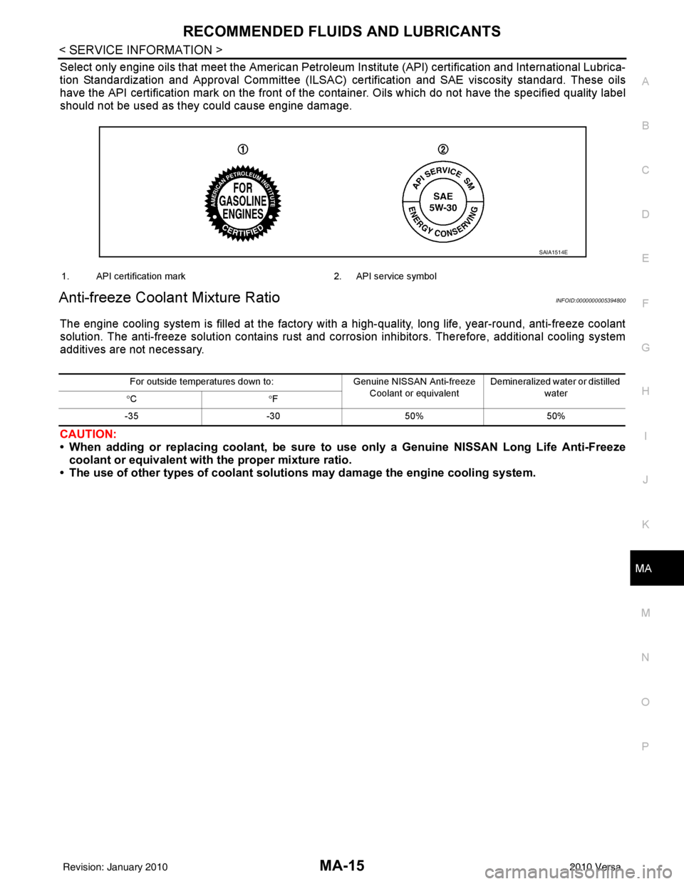
Select only engine oils that meet the American Petroleum Institute (API) certification and International Lubrica-
tion Standardization and Approval Committee (ILSAC) ce rtification and SAE viscosity standard. These oils
have the API certification mark on the front of the container. Oils which do not have the specified quality label
should not be used as they could cause engine damage.
Anti-freeze Coolant Mixture RatioINFOID:0000000005394800
The engine cooling system is filled at the factory wit h a high-quality, long life, year-round, anti-freeze coolant
solution. The anti-freeze solution contains rust and corrosion inhibitors. Therefore, additional cooling system
additives are not necessary.
CAUTION:
• When adding or replacing coolant, be sure to use only a Genuine NISSAN Long Life Anti-Freeze
coolant or equivalent with the proper mixture ratio.
• The use of other types of coolant soluti ons may damage the engine cooling system.
SAIA1514E
1. API certification mark 2. API service symbol
For outside temperatures down to: Genuine NISSAN Anti-freeze
Coolant or equivalent Demineralized water or distilled
water
° C °F
-35 -3050% 50%
Revision: January 20102010 Versa
Page 3154 of 3745
ENGINE MAINTENANCE (HR16DE)MA-19
< SERVICE INFORMATION >
C
DE
F
G H
I
J
K
M A
B
MA
N
O P
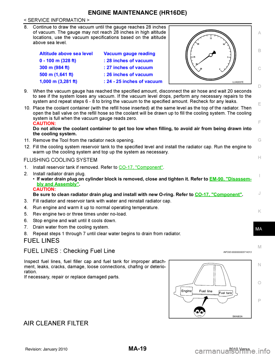
8. Continue to draw the vacuum until the gauge reaches 28 inches of vacuum. The gauge may not reach 28 inches in high altitude
locations, use the vacuum specifications based on the altitude
above sea level.
9. When the vacuum gauge has reached the specified amount, disconnect the air hose and wait 20 seconds
to see if the system loses any vacuum. If the vacuum level drops, perform any necessary repairs to the
system and repeat steps 6 - 8 to br ing the vacuum to the specified amount. Recheck for any leaks.
10. Place the coolant container (with the refill hose inserted) at the same level as the top of the radiator. Then
open the ball valve on the refill hose so the coolant will be drawn up to fill the cooling system. The cooling
system is full when the vacuum gauge reads zero.
CAUTION:
Do not allow the coolant container to get too low when filling, to avoid air from being drawn into
the cooling system.
11. Remove the Tool from the radiator neck opening.
12. Fill the cooling system reservoir tank to the specif ied level and install the radiator cap. Run the engine to
warm up the cooling system and top up the system as necessary.
FLUSHING COOLING SYSTEM
1. Install reservoir tank if removed. Refer to CO-17, "Component".
2. Install radiator drain plug. •If water drain plug on cylinder block is removed, close and tighten it. Refer to EM-90, "
Disassem-
bly and Assembly".
CAUTION:
Be sure to clean radiator drain plug and install with new O-ring. Refer to CO-17, "
Component".
3. Fill radiator and reservoir tank with water and reinstall radiator cap.
4. Run engine and warm it up to normal operating temperature.
5. Rev engine two or three times under no-load.
6. Stop engine and wait until it cools down.
7. Drain water from the cooling system.
8. Repeat steps 1 through 7 until clear water begins to drain from radiator.
FUEL LINES
FUEL LINES : Checking Fuel LineINFOID:0000000005714313
Inspect fuel lines, fuel filler cap and fuel tank for improper attach-
ment, leaks, cracks, damage, loos e connections, chafing or deterio-
ration.
If necessary, repair or replace damaged parts.
AIR CLEANER FILTER
Altitude above sea level Vacuum gauge reading
0 - 100 m (328 ft) : 28 inches of vacuum
300 m (984 ft) : 27 inches of vacuum
500 m (1,641 ft) : 26 inches of vacuum
1,000 m (3,281 ft) : 24 - 25 inches of vacuum
LLIA0057E
SMA803A
Revision: January 20102010 Versa
Page 3332 of 3745
TROUBLE DIAGNOSISMTC-53
< SERVICE INFORMATION >
C
DE
F
G H
I
K L
M A
B
MTC
N
O P
Insufficient HeatingINFOID:0000000005396504
SYMPTOM: Insufficient heating
INSPECTION FLOW
1.CONFIRM SYMPTOM BY PERFORMING OPERAT IONAL CHECK - TEMPERATURE INCREASE
1. Turn temperature control dial clockwise to maximum heat position.
2. Check for hot air at discharge air outlets.
Can the symptom be duplicated?
YES >> GO TO 3.
NO >> GO TO 2.
2.CHECK FOR ANY SYMPTOMS
Perform a complete operational check for any symptoms. Refer to MTC-31, "
Operational Check" .
Does another symptom exist?
YES >> Refer to MTC-23, "How to Perform Trouble Diagnosis for Quick and Accurate Repair" .
NO >> System OK.
3.CHECK FOR SERVICE BULLETINS
Check for any service bulletins.
>> GO TO 4.
4.CHECK COOLANT SYSTEM
1. Check engine coolant level. Refer to CO-12, "
Inspection" (HR16DE) or CO-36, "Inspection" (MR18DE).
2. Check hoses for leaks or kinks.
3. Check Radiator cap. Refer to CO-15, "
Checking Radiator Cap" HR16DE or CO-39, "Checking Radiator
Cap" (MR18DE).
OK or NG
OK >> GO TO 5.
NG >> Repair/replace as necessary.
5.CHECK AIR MIX DOOR CABLE
Check air mix door cable operation. Refer to MTC-65, "
Air Mix Door Cable Adjustment" .
OK or NG
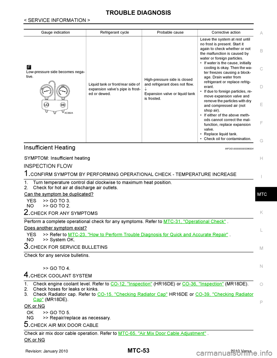
Gauge indication Refrigerant cycleProbable causeCorrective action
Low-pressure side becomes nega-
tive. Liquid tank or front/rear side of
expansion valve’s pipe is frost-
ed or dewed.High-pressure side is closed
and refrigerant does not flow.
↓
Expansion valve or liquid tank
is frosted.Leave the system at rest until
no frost is present. Start it
again to check whether or not
the malfunction is caused by
water or foreign particles.
• If water is the cause, initially
cooling is okay. Then the wa-
ter freezes causing a block-
age. Drain water from
refrigerant or replace refrig-
erant.
• If due to foreign particles, re-
move expansion valve and
remove the particles with dry
and compressed air (not
shop air).
• If either of the above meth- ods cannot correct the mal-
function, replace expansion
valve.
• Replace liquid tank.
• Check oil for contamination.
AC362A
Revision: January 20102010 Versa
Page 3333 of 3745
MTC-54
< SERVICE INFORMATION >
TROUBLE DIAGNOSIS
YES >> GO TO 6.
NO >> Adjust or replace air mix door cable. Refer to MTC-65, "
Air Mix Door Cable Adjustment" .
6.CHECK AIR DUCTS
Check ducts for air leaks.
OK or NG
OK >> GO TO 7.
NG >> Repair air leaks.
7.CHECK HEATER HOSE TEMPERATURES
1. Start engine and warm it up to normal operating temperature.
2. Touch both the inlet and outlet heater hoses. The inlet hose should be hot and the outlet hose should be
warm.
Is the inlet hose hot and the outlet hose warm?
YES >> GO TO 8.
NO >> Both hoses warm: GO TO 9.
8.CHECK ENGINE COOLANT TEMPERATURE SENSOR
Check engine control temperature sensor. Refer to EC-690, "
Component Inspection" (MR18DE) or EC-163,
"Component Inspection" (HR16DE).
OK or NG
OK >> System OK.
NG >> Repair or replace as necessary. Retest.
9.CHECK HEATER HOSES
Check heater hoses for proper installation.
OK or NG
OK >> GO TO 10.
NG >> Repair /replace as necessary. Retest GO TO 7.
10.BACK FLUSH HEATER CORE
1. Back flush heater core.
2. Drain the water from the system.
3. Refill system with new engine coolant. Refer to CO-12, "
Changing Engine Coolant" (HR16DE) or CO-36,
"Changing Engine Coolant" (MR18DE) .
4. Start engine and warm it up to normal operating temperature.
5. Touch both the inlet and outlet heater hoses. The inlet hose should be hot and the outlet hose should be
warm.
Is the inlet hose hot and the outlet hose warm?
YES >> System OK.
NO >> Replace heater core and refill engine coolant. Refer to MTC-68, "
Removal and Installation" .
NoiseINFOID:0000000005396505
SYMPTOM: Noise
INSPECTION FLOW
Revision: January 20102010 Versa
Page 3429 of 3745
PG-46
< SERVICE INFORMATION >
HARNESS
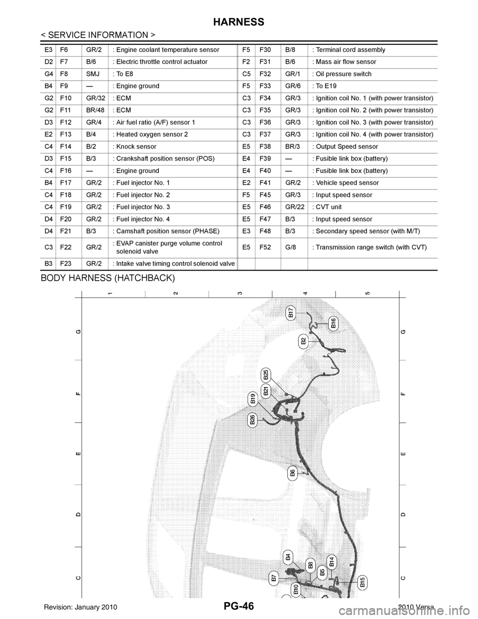
BODY HARNESS (HATCHBACK)
E3 F6 GR/2 : Engine coolant temperature sensor F5 F30 B/8 : Terminal cord assembly
D2 F7 B/6 : Electric throttle control actuatorF2 F31 B/6 : Mass air flow sensor
G4 F8 SMJ : To E8 C5 F32 GR/1 : Oil pressure switch
B4 F9 — : Engine ground F5 F33 GR/6 : To E19
G2 F10 GR/32 : ECM C3 F34 GR/3 : Ignition coil No. 1 (with power transistor)
G2 F11 BR/48 : ECM C3 F35 GR/3 : Ignition coil No. 2 (with power transistor)
D3 F12 GR/4 : Air fuel ratio (A/F) sensor 1 C3 F36 GR/3 : Ignition coil No. 3 (with power transistor)
E2 F13 B/4 : Heated oxygen sensor 2 C3 F37 GR/3 : Ignition coil No. 4 (with power transistor)
C4 F14 B/2 : Knock sensor E5 F38 BR/3 : Output Speed sensor
D3 F15 B/3 : Crankshaft position sensor (POS) E4 F39 — : Fusible link box (battery)
C4 F16 — : Engine ground E4 F40 — : Fusible link box (battery)
B4 F17 GR/2 : Fuel injector No. 1 E2 F41 GR/2 : Vehicle speed sensor
C4 F18 GR/2 : Fuel injector No. 2 F5 F45 GR/3 : Input speed sensor
C4 F19 GR/2 : Fuel injector No. 3E5 F46 GR/22 : CVT unit
D4 F20 GR/2 : Fuel injector No. 4 E5 F47 B/3 : Input speed sensor
D4 F21 B/3 : Camshaft position sensor (PHASE) E3 F48 B/3 : Secondary speed sensor (with M/T)
C3 F22 GR/2 : EVAP canister purge volume control
solenoid valve E5 F52 G/8 : Transmission range switch (with CVT)
B3 F23 GR/2 : Intake valve timing control solenoid valve
Revision: January 20102010 Versa