2010 NISSAN MURANO lights
[x] Cancel search: lightsPage 166 of 425

Black plate (162,1)
Model "Z51-D" EDITED: 2009/ 8/ 3
SPA2422A
Type A
SPA2450
Type B
Automatic anti-glare typeThe inside mirror is designed so that it
automatically changes reflection according to
the intensity of the headlights of the following
vehicle.
The anti-glare system will be automatically
turned on when the ignition switch is pushed
to the ON position.
When the anti-glare system is turned on, the
indicator light
*A
will illuminate and excessive
glare from the headlights of the vehicle behind
you will be reduced.
Type A: Push the
switch
*B
to make the
inside rearview mirror operate normally and the
indicator light will turn off. Push the
switch
again to turn the system on.
Type B: Push the “* ” switch
*C
to make the
inside rearview mirror operate normally. The
indicator light will turn off. Push the “I” switch
*D
to turn the system on.
Do not allow any object to cover the
sensors
*E
or apply glass cleaner on
them. Doing so will reduce the sensitivity
of the sensor, resulting in improper opera-
tion.
For the compass (if so equipped) operation, see
“COMPASS” in the “2. Instruments and con-
trols” section. For the HomeLink
®Universal Transceiver opera-
tion, see “HomeLink®UNIVERSAL TRANSCEI-
VER” in the “2. Instruments and controls”
section.
3-28
Pre-driving checks and adjustments
Page 168 of 425
Black plate (164,1)
Model "Z51-D" EDITED: 2009/ 8/ 3
SIC2064
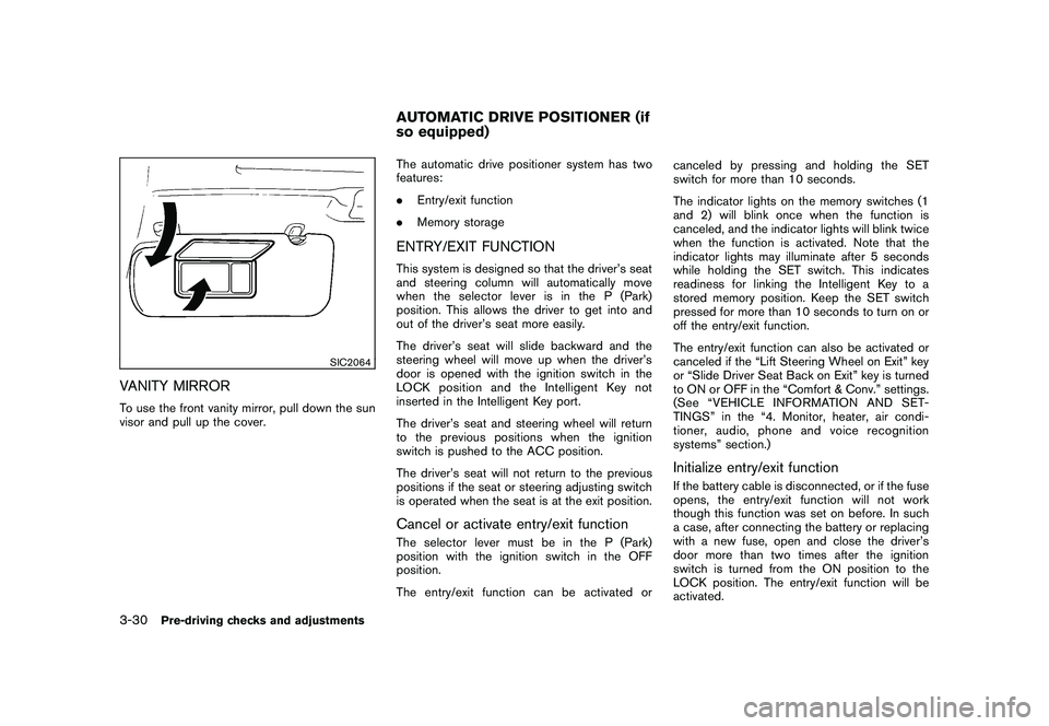
VANITY MIRRORTo use the front vanity mirror, pull down the sun
visor and pull up the cover.The automatic drive positioner system has two
features:
.
Entry/exit function
. Memory storage
ENTRY/EXIT FUNCTIONThis system is designed so that the driver’s seat
and steering column will automatically move
when the selector lever is in the P (Park)
position. This allows the driver to get into and
out of the driver’s seat more easily.
The driver’s seat will slide backward and the
steering wheel will move up when the driver’s
door is opened with the ignition switch in the
LOCK position and the Intelligent Key not
inserted in the Intelligent Key port.
The driver’s seat and steering wheel will return
to the previous positions when the ignition
switch is pushed to the ACC position.
The driver’s seat will not return to the previous
positions if the seat or steering adjusting switch
is operated when the seat is at the exit position.Cancel or activate entry/exit functionThe selector lever must be in the P (Park)
position with the ignition switch in the OFF
position.
The entry/exit function can be activated or canceled by pressing and holding the SET
switch for more than 10 seconds.
The indicator lights on the memory switches (1
and 2) will blink once when the function is
canceled, and the indicator lights will blink twice
when the function is activated. Note that the
indicator lights may illuminate after 5 seconds
while holding the SET switch. This indicates
readiness for linking the Intelligent Key to a
stored memory position. Keep the SET switch
pressed for more than 10 seconds to turn on or
off the entry/exit function.
The entry/exit function can also be activated or
canceled if the “Lift Steering Wheel on Exit” key
or “Slide Driver Seat Back on Exit” key is turned
to ON or OFF in the “Comfort & Conv.” settings.
(See “VEHICLE INFORMATION AND SET-
TINGS” in the “4. Monitor, heater, air condi-
tioner, audio, phone and voice recognition
systems” section.)
Initialize entry/exit functionIf the battery cable is disconnected, or if the fuse
opens, the entry/exit function will not work
though this function was set on before. In such
a case, after connecting the battery or replacing
with a new fuse, open and close the driver’s
door more than two times after the ignition
switch is turned from the ON position to the
LOCK position. The entry/exit function will be
activated.
AUTOMATIC DRIVE POSITIONER (if
so equipped)
3-30
Pre-driving checks and adjustments
Page 189 of 425
Black plate (185,1)
Model "Z51-D" EDITED: 2009/ 8/ 3
SAA1564SAA1565
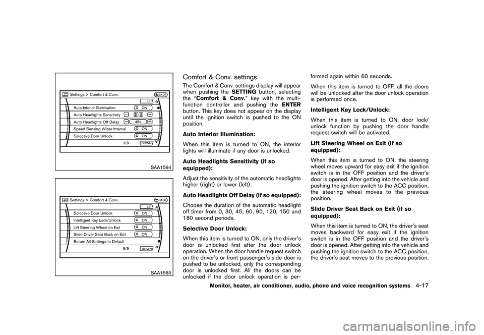
Comfort & Conv. settingsThe Comfort & Conv. settings display will appear
when pushing theSETTINGbutton, selecting
the “Comfort & Conv. ” key with the multi-
function controller and pushing the ENTER
button. This key does not appear on the display
until the ignition switch is pushed to the ON
position.
Auto Interior Illumination:
When this item is turned to ON, the interior
lights will illuminate if any door is unlocked.
Auto Headlights Sensitivity (if so
equipped):
Adjust the sensitivity of the automatic headlights
higher (right) or lower (left) .
Auto Headlights Off Delay (if so equipped):
Choose the duration of the automatic headlight
off timer from 0, 30, 45, 60, 90, 120, 150 and
180 second periods.
Selective Door Unlock:
When this item is turned to ON, only the driver’s
door is unlocked first after the door unlock
operation. When the door handle request switch
on the driver’s or front passenger’s side door is
pushed to be unlocked, only the corresponding
door is unlocked first. All the doors can be
unlocked if the door unlock operation is per- formed again within 60 seconds.
When this item is turned to OFF, all the doors
will be unlocked after the door unlock operation
is performed once.
Intelligent Key Lock/Unlock:
When this item is turned to ON, door lock/
unlock function by pushing the door handle
request switch will be activated.
Lift Steering Wheel on Exit (if so
equipped):
When this item is turned to ON, the steering
wheel moves upward for easy exit if the ignition
switch is in the OFF position and the driver’s
door is opened. After getting into the vehicle and
pushing the ignition switch to the ACC position,
the steering wheel moves to the previous
position.
Slide Driver Seat Back on Exit (if so
equipped):
When this item is turned to ON, the driver’s seat
moves backward for easy exit if the ignition
switch is in the OFF position and the driver’s
door is opened. After getting into the vehicle and
pushing the ignition switch to the ACC position,
the driver’s seat moves to the previous position.
Monitor, heater, air conditioner, audio, phone and voice recognition systems
4-17
Page 201 of 425
Black plate (197,1)
Model "Z51-D" EDITED: 2009/ 8/ 3
.The temperature of the passenger compart-
ment will be maintained automatically. Air
flow distribution and fan speed are also
controlled automatically.
. Do not set the temperature lower than the
outside air temperature. Otherwise the
system may not work properly.
. Not recommended if windows fog up.Dehumidified defrosting or defogging1. Push the “
” front defroster button. (The
indicator light on the button will come on.)
2. Operate the temperature control buttons (type A) dial (type B) to set the desired
temperature.
. To quickly remove ice from the outside of the
windows, turn the “
” fan speed control
dial and set it to the maximum position.
. As soon as possible after the windshield is
clean, push the “AUTO” button to return to
the auto mode.
. When the “
” front defroster button is
pushed, the air conditioner will automatically
be turned on at outside temperatures above
23 8F( �58C) to defog the windshield, and
the air recirculate mode will automatically be
turned off.
Outside air is drawn into the passenger compartment to improve the defogging
performance.
MANUAL OPERATION
Fan speed controlTu r n t h e “
” fan speed control dial to
manually control the fan speed.
Push the “AUTO” button to return to automatic
control of the fan speed.
Air recirculationPush the intake air control button “
”to
recirculate interior air inside the vehicle. The
indicator light “
” will come on.
The air recirculation mode cannot be activated
when the air conditioner is in the front defrosting
mode “
”.
Outside air circulationPush the intake air control button “
”to
change the air circulation from the intake air to
the outside air. The indicator light “
” will turn
off.
Automatic air intake controlIn the AUTO mode, the intake air will be
controlled automatically. To manually control
the intake air, push the intake air control button
“
”. To return to the automatic control mode,
push the intake air control button “
” for about 2 seconds. The indicator lights will flash
twice, and then the intake air will be controlled
automatically.
Air flow controlPushing the “MODE” manual air flow control
button selects the air outlet to:
: Air flows from center and side ventila-
tors.: Air flows from center and side ventila-tors and foot outlets.: Air flows mainly from foot outlets.: Air flows from defroster and foot out-lets.
Upper vent systemWhen the “
” upper vent button is pushed,
the air flow against the driver’s or passenger’s
upper body becomes gentle. The indicator light
on the button will come on.
In this mode, air from the center ventilators flows
both straight and upward in order to control the
cabin temperature without blowing air directly
on the occupants.
If you want strong air flow against your upper
body, push the “
” button to turn the
indicator light off.
Monitor, heater, air conditioner, audio, phone and voice recognition systems
4-29
Page 204 of 425
Black plate (200,1)
Model "Z51-D" EDITED: 2009/ 8/ 3
Static and flutter: During signal interference from
buildings, large hills or due to antenna position,
usually in conjunction with increased distance
from the station transmitter, static or flutter can
be heard. This can be reduced by lowering the
treble setting to reduce the treble response.
Multipath reception: Because of the reflective
characteristics of FM signals, direct and re-
flected signals reach the receiver at the same
time. The signals may cancel each other,
resulting in momentary flutter or loss of sound.
AM radio reception:
AM signals, because of their low frequency, can
bend around objects and skip along the ground.
In addition, the signals can be bounced off the
ionosphere and bent back to earth. Because of
these characteristics. AM signals are also
subject to interference as they travel from
transmitter to receiver.
Fading: Occurs while the vehicle is passing
through freeway underpasses or in areas with
many tall buildings. It can also occur for several
seconds during ionospheric turbulence even in
areas where no obstacles exist.
Static: Caused by thunderstorms, electrical
power lines, electric signs and even traffic lights.Satellite radio reception (if so equipped):
When the satellite radio is first installed or the
battery has been replaced, the satellite radio
may not work properly. This is not a malfunction.
Wait more than 10 minutes with satellite radio
ON for satellite radio to receive all of the
necessary data.
The satellite radio mode requires an active XM
®
satellite radio service subscription. Satellite
radio is not available in Alaska, Hawaii and
Guam.
Satellite radio performance may be affected if
cargo carried on the roof blocks the satellite
radio signal.
If possible, do not put cargo near the satellite
antenna.
A build up of ice on the satellite radio antenna
can affect satellite radio performance. Remove
the ice to restore satellite radio reception.
SAA0480
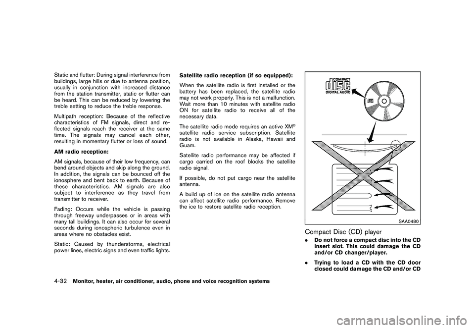
Compact Disc (CD) player.
Do not force a compact disc into the CD
insert slot. This could damage the CD
and/or CD changer/player.
. Trying to load a CD with the CD door
closed could damage the CD and/or CD
4-32
Monitor, heater, air conditioner, audio, phone and voice recognition systems
Page 306 of 425
Black plate (302,1)
Model "Z51-D" EDITED: 2009/ 8/ 3
INTELLIGENT KEY BATTERY DIS-
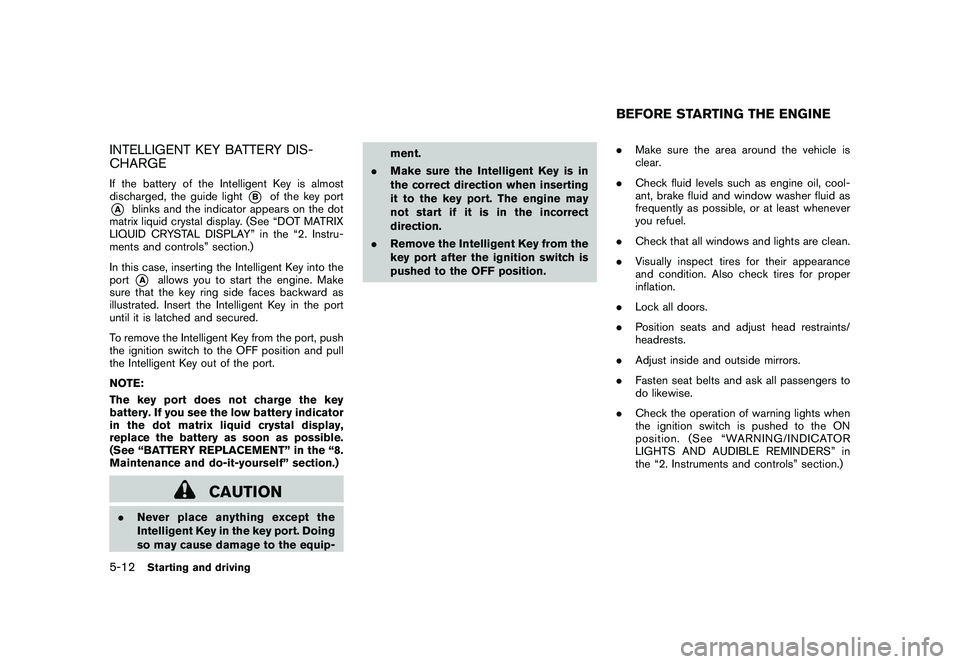
CHARGEIf the battery of the Intelligent Key is almost
discharged, the guide light
*B
of the key port
*A
blinks and the indicator appears on the dot
matrix liquid crystal display. (See “DOT MATRIX
LIQUID CRYSTAL DISPLAY” in the “2. Instru-
ments and controls” section.)
In this case, inserting the Intelligent Key into the
port*A
allows you to start the engine. Make
sure that the key ring side faces backward as
illustrated. Insert the Intelligent Key in the port
until it is latched and secured.
To remove the Intelligent Key from the port, push
the ignition switch to the OFF position and pull
the Intelligent Key out of the port.
NOTE:
The key port does not charge the key
battery. If you see the low battery indicator
in the dot matrix liquid crystal display,
replace the battery as soon as possible.
(See “BATTERY REPLACEMENT” in the “8.
Maintenance and do-it-yourself” section.)
CAUTION
. Never place anything except the
Intelligent Key in the key port. Doing
so may cause damage to the equip- ment.
. Make sure the Intelligent Key is in
the correct direction when inserting
it to the key port. The engine may
not start if it is in the incorrect
direction.
. Remove the Intelligent Key from the
key port after the ignition switch is
pushed to the OFF position. .
Make sure the area around the vehicle is
clear.
. Check fluid levels such as engine oil, cool-
ant, brake fluid and window washer fluid as
frequently as possible, or at least whenever
you refuel.
. Check that all windows and lights are clean.
. Visually inspect tires for their appearance
and condition. Also check tires for proper
inflation.
. Lock all doors.
. Position seats and adjust head restraints/
headrests.
. Adjust inside and outside mirrors.
. Fasten seat belts and ask all passengers to
do likewise.
. Check the operation of warning lights when
the ignition switch is pushed to the ON
position. (See “WARNING/INDICATOR
LIGHTS AND AUDIBLE REMINDERS” in
the “2. Instruments and controls” section.)
BEFORE STARTING THE ENGINE
5-12
Starting and driving
Page 311 of 425
Black plate (307,1)
Model "Z51-D" EDITED: 2009/ 8/ 3
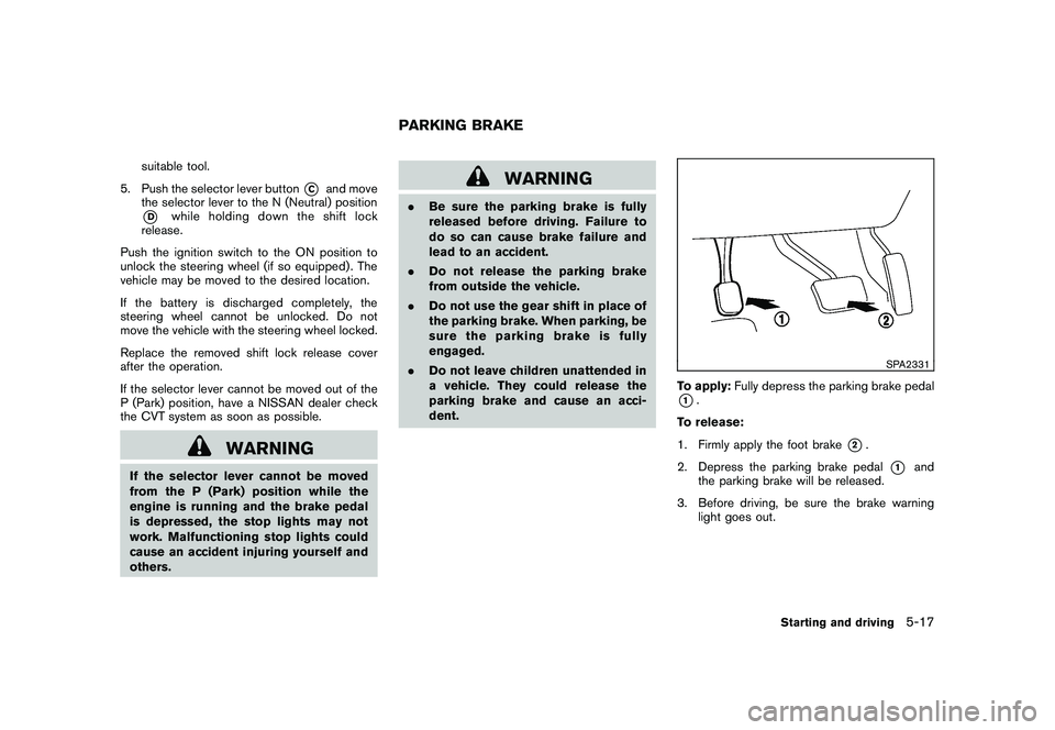
suitable tool.
5. Push the selector lever button
*C
and move
the selector lever to the N (Neutral) position
*D
while holding down the shift lock
release.
Push the ignition switch to the ON position to
unlock the steering wheel (if so equipped) . The
vehicle may be moved to the desired location.
If the battery is discharged completely, the
steering wheel cannot be unlocked. Do not
move the vehicle with the steering wheel locked.
Replace the removed shift lock release cover
after the operation.
If the selector lever cannot be moved out of the
P (Park) position, have a NISSAN dealer check
the CVT system as soon as possible.
WARNING
If the selector lever cannot be moved
from the P (Park) position while the
engine is running and the brake pedal
is depressed, the stop lights may not
work. Malfunctioning stop lights could
cause an accident injuring yourself and
others.
WARNING
. Be sure the parking brake is fully
released before driving. Failure to
do so can cause brake failure and
lead to an accident.
. Do not release the parking brake
from outside the vehicle.
. Do not use the gear shift in place of
the parking brake. When parking, be
sure the parking brake is fully
engaged.
. Do not leave children unattended in
a vehicle. They could release the
parking brake and cause an acci-
dent.
SPA2331
To apply: Fully depress the parking brake pedal*1.
To release:
1. Firmly apply the foot brake
*2.
2. Depress the parking brake pedal
*1
and
the parking brake will be released.
3. Before driving, be sure the brake warning light goes out.
PARKING BRAKE
Starting and driving
5-17
Page 321 of 425

Black plate (317,1)
Model "Z51-D" EDITED: 2009/ 8/ 3
applies and releases hydraulic pressure. This
action is similar to pumping the brakes very
quickly. You may feel a pulsation in the brake
pedal and hear a noise from under the hood or
feel a vibration from the actuator when it is
operating. This is normal and indicates that the
ABS is operating properly. However, the pulsa-
tion may indicate that road conditions are
hazardous and extra care is required while
driving.The Vehicle Dynamic Control (VDC) system
uses various sensors to monitor driver inputs
and vehicle motion. Under certain driving con-
ditions, the VDC system helps to perform the
following functions.
.
Controls brake pressure to reduce tire slip
on one slipping drive wheel so power is
transferred to a non slipping drive wheel on
the same axle.
. Controls brake pressure and engine output
to reduce drive wheel slip based on vehicle
speed (traction control function) .
. Controls brake pressure at individual wheels
and engine output to help the driver maintain
control of the vehicle in the following
conditions:
— understeer (vehicle tends to not follow the steered path despite increased steering
input)
— oversteer (vehicle tends to spin due to certain road or driving conditions) .
The VDC system can help the driver to maintain
control of the vehicle, but it cannot prevent loss
of vehicle control in all driving situations.
When the VDC system operates, the
indicator in the instrument panel flashes so note
the following:
. The road may be slippery or the system may determine some action is required to keep
the vehicle on the steered path.
. You may feel a pulsation in the brake pedal
and hear a noise or vibration from under the
hood. This is normal and indicates that the
VDC system is working properly.
. Adjust your speed and driving to the road
conditions.
. Indicator light
If a malfunction occurs in the system, the
and
indicator lights come on in
the instrument panel. The VDC system
automatically turns off when these indicator
lights are on.
. The ABLS system uses automatic braking to
transfer power from a slipping drive wheel to
the wheel on the same axle with more
traction. The ABLS system applies braking
to the slipping wheel, which helps redirect
power to another wheel.
. The ABLS system is always ON unless the
system detects brake pad overheating. If
high brake pad temperature is detected, it
will turn OFF, but normal brake function will
continue. ABLS will function even when the
VDC system is turned OFF. The ABLS
system does not operate if both wheels on
a drive axle are slipping.
VEHICLE DYNAMIC CONTROL (VDC)
SYSTEM
Starting and driving
5-27