2010 NISSAN LATIO air condition
[x] Cancel search: air conditionPage 217 of 3745

AT-200
< SERVICE INFORMATION >
TROUBLE DIAGNOSIS FOR SYMPTOMS
OK >> GO TO 3
NG >> Check transmission range switch. Refer to AT-175, "
Component Inspection" .
2.CHECK TRANSMISSION RANGE SWITCH CIRCUIT
Without CONSULT-III
1. Turn ignition switch ON. (Do not start engine.)
2. Check voltage between TCM connector terminals and ground
while moving selector lever through each position. Refer to AT-
91, "Wiring Diagram - AT - TR/SW" .
B: Battery voltage
0: 0V
OK or NG
OK >> GO TO 3
NG >> Check transmission range switch. Refer to AT-175, "
Component Inspection" .
3.CHECK A/T POSITION
Check A/T position. Refer to AT-217, "
Checking of A/T Position" .
OK or NG
OK >> GO TO 4.
NG >> Adjust A/T position. Refer to AT-217, "
Adjustment of A/T Position" .
4.CHECK OUTPUT SPEED SENSOR AND VEHICLE SPEED SIGNAL CIRCUIT
Check output speed sensor and vehicle speed signal circuit. Refer to AT-100
and/or AT-153 .
OK or NG
OK >> GO TO 5.
NG >> Repair or replace output speed sens or and/or vehicle speed signal circuits.
5.CHECK A/T FLUID CONDITION
1. Remove oil pan. Refer to AT-237, "
Component" .
2. Check A/T fluid condition. Refer to AT-51, "
Inspections Before Trouble Diagnosis" .
OK or NG
OK >> GO TO 7.
NG >> GO TO 6.
6.DETECT MALFUNCTIONING ITEM
1. Remove control valve assembly. Refer to AT-222, "
Control Valve Assembly and Accumulators" .
2. Check the following items:
- Shift valve A
- Shift solenoid valve A
Selector lever position Te r m i n a l
36 35 34 27 26
“P”, “N” B0000 “R” 0B000
“D” 0 0 B 0 0
“2” 000B0
“1” 0000B
SCIA7162E
Revision: January 20102010 Versa
Page 220 of 3745

TROUBLE DIAGNOSIS FOR SYMPTOMSAT-203
< SERVICE INFORMATION >
DE
F
G H
I
J
K L
M A
B
AT
N
O P
2. Check voltage between TCM connector terminals and ground while moving selector lever through each position. Refer to AT-
91, "Wiring Diagram - AT - TR/SW" .
B: Battery voltage
0: 0V
OK or NG
OK >> GO TO 5
NG >> Check transmission range switch. Refer to AT-175, "
Component Inspection" .
5.CHECK A/T POSITION
Check A/T position. Refer to AT-217, "
Checking of A/T Position" .
OK or NG
OK >> GO TO 6.
NG >> Adjust A/T position. Refer to AT-217, "
Adjustment of A/T Position" .
6.CHECK OUTPUT SPEED SENSOR AND VEHICLE SPEED SIGNAL CIRCUIT
Check output speed sensor and vehicle speed signal circuit. Refer to AT-100
and/or AT- 1 5 3 .
OK or NG
OK >> GO TO 7.
NG >> Repair or replace output speed sensor and/or vehicle speed signal circuits.
7.CHECK ACCELERATOR PEDAL POSITION SENSOR
Check accelerator pedal position sensor. Refer to EC-405, "
Description" (HR16DE), EC-982, "Component
Description" (MR18DE).
OK or NG
OK >> GO TO 8.
NG >> Repair or replace accelerator pedal position sensor.
8.CHECK A/T FLUID CONDITION
1. Remove oil pan. Refer to AT-237, "
Component" .
2. Check A/T fluid condition. Refer to AT-51, "
Inspections Before Trouble Diagnosis" .
OK or NG
OK >> GO TO 10.
NG >> GO TO 9.
9.DETECT MALFUNCTIONING ITEM
1. Remove control valve assembly. Refer to AT-222, "
Control Valve Assembly and Accumulators" .
2. Check the following.
- Shift valve A
Selector lever position Te r m i n a l
36 35 34 27 26
“P”, “N” B 0 0 0 0
“R” 0B000
“D” 0 0 B 0 0
“2” 0 0 0 B 0
“1” 0 0 0 0 B
SCIA7162E
Revision: January 20102010 Versa
Page 226 of 3745

A/T SHIFT LOCK SYSTEMAT-209
< SERVICE INFORMATION >
DE
F
G H
I
J
K L
M A
B
AT
N
O P
• Selector lever can be moved fr om “P” position with ignition key in ON position and brake pedal
released.
• Selector lever can be moved from “P” position when ignition switch is removed from key cylinder.
SYMPTOM 2:
• Ignition key cannot be removed when sel ector lever is set to “P” position.
• Ignition key can be removed wh en selector lever is set to any position except “P” position.
1.CHECK KEY INTERLOCK CABLE
Check key interlock cable for damage.
OK or NG
OK >> GO TO 2.
NG >> Repair key interlock cable. Refer to AT-219, "
Removal and Installation" .
2.CHECK A/T POSITION
Check A/T position. Refer to AT-217, "
Checking of A/T Position" .
OK or NG
OK >> GO TO 3.
NG >> Adjust control cable. Refer to AT-217, "
Adjustment of A/T Position" .
3.CHECK SHIFT LOCK SOLENOID AND PARK POSITION SWITCH
1. Turn ignition switch ON. (Do not start engine.)
2. Selector lever is set in “P” position.
3. Check operation sound.
OK or NG
OK >> INSPECTION END
NG - 1 >> With intelligent key: GO TO 4.
NG - 2 >> Without intelligent key: GO TO 5.
4.CHECK POWER SOURCE
1. Turn ignition switch ON. (Do not start engine.)
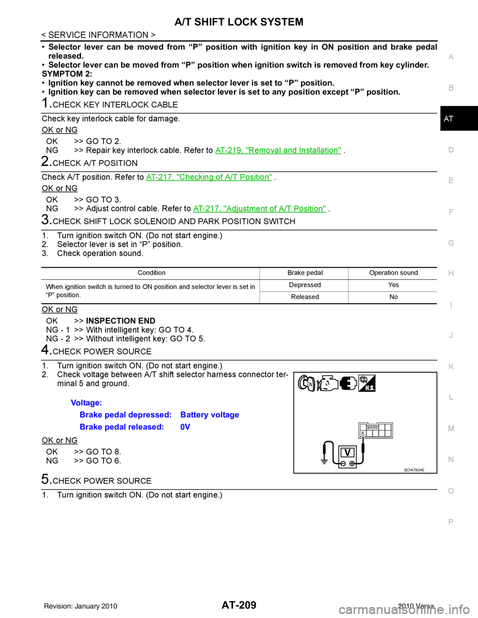
2. Check voltage between A/T shift selector harness connector ter- minal 5 and ground.
OK or NG
OK >> GO TO 8.
NG >> GO TO 6.
5.CHECK POWER SOURCE
1. Turn ignition switch ON. (Do not start engine.)
Condition Brake pedalOperation sound
When ignition switch is turned to ON position and selector lever is set in
“P” position. Depressed
Yes
Released No
Voltage:
Brake pedal depressed: Battery voltage
Brake pedal released: 0V
SCIA7934E
Revision: January 20102010 Versa
Page 227 of 3745

AT-210
< SERVICE INFORMATION >
A/T SHIFT LOCK SYSTEM
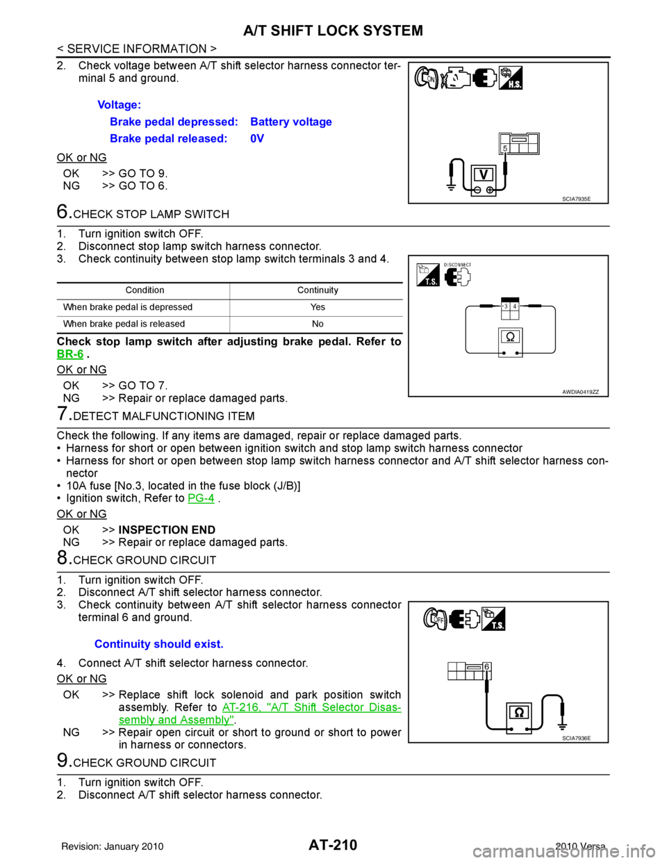
2. Check voltage between A/T shift selector harness connector ter-minal 5 and ground.
OK or NG
OK >> GO TO 9.
NG >> GO TO 6.
6.CHECK STOP LAMP SWITCH
1. Turn ignition switch OFF.
2. Disconnect stop lamp switch harness connector.
3. Check continuity between stop lamp switch terminals 3 and 4.
Check stop lamp switch after adjusting brake pedal. Refer to
BR-6
.
OK or NG
OK >> GO TO 7.
NG >> Repair or replace damaged parts.
7.DETECT MALFUNCTIONING ITEM
Check the following. If any items are damaged, repair or replace damaged parts.
• Harness for short or open between ignition switch and stop lamp switch harness connector
• Harness for short or open between stop lamp switch harness connector and A/T shift selector harness con-
nector
• 10A fuse [No.3, located in the fuse block (J/B)]
• Ignition switch, Refer to PG-4
.
OK or NG
OK >> INSPECTION END
NG >> Repair or replace damaged parts.
8.CHECK GROUND CIRCUIT
1. Turn ignition switch OFF.
2. Disconnect A/T shift selector harness connector.
3. Check continuity between A/T shift selector harness connector terminal 6 and ground.
4. Connect A/T shift selector harness connector.
OK or NG
OK >> Replace shift lock solenoid and park position switch assembly. Refer to AT-216, "
A/T Shift Selector Disas-
sembly and Assembly".
NG >> Repair open circuit or short to ground or short to power in harness or connectors.
9.CHECK GROUND CIRCUIT
1. Turn ignition switch OFF.
2. Disconnect A/T shift selector harness connector. Voltage:
Brake pedal depressed: Battery voltage
Brake pedal released: 0V
SCIA7935E
Condition Continuity
When brake pedal is depressed Yes
When brake pedal is released No
AWDIA0419ZZ
Continuity should exist.
SCIA7936E
Revision: January 20102010 Versa
Page 421 of 3745
![NISSAN LATIO 2010 Service Repair Manual AV-24
< SERVICE INFORMATION >[AUDIO WITHOUT NAVIGATION]
AUDIO
OK or NG
OK >> Inspection End.
NG >> Replace steering switch. Refer to AV-29, "
Removal and Installation" .
Sound Is Not Heard fr
om Front NISSAN LATIO 2010 Service Repair Manual AV-24
< SERVICE INFORMATION >[AUDIO WITHOUT NAVIGATION]
AUDIO
OK or NG
OK >> Inspection End.
NG >> Replace steering switch. Refer to AV-29, "
Removal and Installation" .
Sound Is Not Heard fr
om Front](/manual-img/5/57358/w960_57358-420.png)
AV-24
< SERVICE INFORMATION >[AUDIO WITHOUT NAVIGATION]
AUDIO
OK or NG
OK >> Inspection End.
NG >> Replace steering switch. Refer to AV-29, "
Removal and Installation" .
Sound Is Not Heard fr
om Front Door Speaker (Base System)INFOID:0000000005395325
1.HARNESS CHECK
1. Disconnect audio unit connector and front door speaker connector (LH or RH).
2. Check continuity between audio unit connector M43 (A) terminal and suspect speaker connector (B) terminal.
3. Check continuity between audio unit connector M43 terminal and ground.
OK or NG
OK >> GO TO 2.
NG >> • Check connector housings for disconnected or loose terminals. • Repair harness or connector.
2.FRONT SPEAKER SIGNAL CHECK
1. Connect audio unit connector and suspect speaker connector.
2. Turn ignition switch to ACC.
3. Push “POWER” switch.
Terminal Signal name ConditionResistance
(Ω)
(Approx.)
16 17 Seek (down) Depress Seek down switch.
165
Phone/Send Depress Phone/Send switch. 0
Volume (down) Depress volume down switch. 487
20 17 Seek (up) Depress Seek up switch.
165
Phone/End Depress Phone/End switch. 0
Volume (up) Depress volume up switch. 487
LKIA0191E
Te r m i n a l s
Continuity
A B
Connector Terminal Connector Terminal
M43 2
D12 +
Ye s
3-
11 D112 +
12 -
Te r m i n a l s Continuity
Audio unit
—
Connector Terminal
M43 2
Ground No
3
11
12
WKIA5444E
Revision: January 20102010 Versa
Page 440 of 3745
![NISSAN LATIO 2010 Service Repair Manual TELEPHONEAV-43
< SERVICE INFORMATION > [AUDIO WITHOUT NAVIGATION]
C
D
E
F
G H
I
J
L
M A
B
AV
N
O P
3. Check steering wheel audio control switch. Refer to AV-22, "Steering Switch Check (With Bluetooth NISSAN LATIO 2010 Service Repair Manual TELEPHONEAV-43
< SERVICE INFORMATION > [AUDIO WITHOUT NAVIGATION]
C
D
E
F
G H
I
J
L
M A
B
AV
N
O P
3. Check steering wheel audio control switch. Refer to AV-22, "Steering Switch Check (With Bluetooth](/manual-img/5/57358/w960_57358-439.png)
TELEPHONEAV-43
< SERVICE INFORMATION > [AUDIO WITHOUT NAVIGATION]
C
D
E
F
G H
I
J
L
M A
B
AV
N
O P
3. Check steering wheel audio control switch. Refer to AV-22, "Steering Switch Check (With Bluetooth)".
OK or NG
OK >> GO TO 2.
NG >> Replace steering wheel audio control switch. AV-29, "
Removal and Installation".
2.CHECK AUDIO UNIT
1. Turn ignition switch ON.
2. Check voltage between audio unit harness connector M43 ter- minals 6, 16 and ground.
OK or NG
OK >> Replace audio unit. Refer to AV-29, "Removal and
Installation".
NG >> GO TO 5.
3.CHECK BLUETOOTH CONTROL UNIT
1. Turn ignition switch ON.
2. Check voltage between Bluetooth control unit harness connec- tor B121 terminals 17, 18 and ground.
OK or NG
OK >> Repair or replace harness.
NG >> Replace Bluetooth control unit. AV-45, "
Removal and
Installation".
Voice Activated Control Function Does Not OperateINFOID:0000000005395343
NOTE:
Even under the normal condition, Bluetooth voice guidance may not occur when pressing steering wheel
audio control switch.
BLUETOOTH VOICE GUIDANCE IS HEARD WHEN PRESSING STEERING WHEEL AUDIO CON-
TROL SWITCH
1.CHECK HARNESS BETWEEN BL UETOOTH CONTROL UNIT AND BLUETOOTH MICROPHONE
1. Turn ignition switch OFF.
2. Disconnect Bluetooth control unit c onnector and Bluetooth microphone connector.
3. Check continuity between Bluetooth control unit connector B121 (A) and Bluetooth microphone connector R15 (B).
4. Check continuity between Bluetooth control unit harness con- nector B121 and ground.6 - Ground
: Approx. 5 V
16 - Ground : Approx. 5 V
LKIA0776E
17 - Ground: Approx. 5 V
18 - Ground : Approx. 5 V
LKIA0777E
Te r m i n a l s
Continuity
Connector Terminal Connector Terminal
A: B121 7
B: R15 1
Ye s
82
29 4
WKIA5795E
Revision: January 20102010 Versa
Page 480 of 3745
![NISSAN LATIO 2010 Service Repair Manual TELEPHONEAV-83
< SERVICE INFORMATION > [AUDIO WITH NAVIGATION]
C
D
E
F
G H
I
J
L
M A
B
AV
N
O P
2. Check continuity between the following Bluetooth control unit terminals and ground.
OK or NG
OK >> In NISSAN LATIO 2010 Service Repair Manual TELEPHONEAV-83
< SERVICE INFORMATION > [AUDIO WITH NAVIGATION]
C
D
E
F
G H
I
J
L
M A
B
AV
N
O P
2. Check continuity between the following Bluetooth control unit terminals and ground.
OK or NG
OK >> In](/manual-img/5/57358/w960_57358-479.png)
TELEPHONEAV-83
< SERVICE INFORMATION > [AUDIO WITH NAVIGATION]
C
D
E
F
G H
I
J
L
M A
B
AV
N
O P
2. Check continuity between the following Bluetooth control unit terminals and ground.
OK or NG
OK >> Inspection End.
NG >> Repair or replace harness.
Steering Wheel Audio Contro l Switch Does Not OperateINFOID:0000000005988554
Refer to AV-68, "Steering Switch Check".
Voice Activated Control F unction Does Not OperateINFOID:0000000005924435
NOTE:
Even under the normal condition, Bluetooth voice guidance may not occur when pressing steering wheel
audio control switch.
BLUETOOTH VOICE GUIDANCE IS HEARD WHEN PRESSING STEERING WHEEL AUDIO CON-
TROL SWITCH
1.CHECK HARNESS BETWEEN BL UETOOTH CONTROL UNIT AND BLUETOOTH MICROPHONE
1. Turn ignition switch OFF.
2. Disconnect Bluetooth control unit c onnector and Bluetooth microphone connector.
3. Check continuity between Bluetooth control unit connector B121 (A) and Bluetooth microphone connector R15 (B).
4. Check continuity between Bluetooth control unit harness con- nector B121 and ground.
OK or NG
OK >> GO TO 2.
NG >> Repair harness or connector.
2.CHECK BLUETOOTH MICROPHONE POWER SUPPLY
1. Connect Bluetooth control unit connector and Bluetooth microphone connector.
2. Turn ignition switch ON.
Te r m i n a l s Continuity
Connector Terminal—
B121 4
Ground Yes
21
27
AWNIA2213ZZ
Te r m i n a l s
Continuity
Connector Terminal Connector Terminal
A: B121 7
B: R15 1
Ye s
82
29 4
Te r m i n a l s Continuity
Connector Terminal —
A: B121 7
Ground No
8
29
WKIA5795E
Revision: January 20102010 Versa
Page 506 of 3745

BCM (BODY CONTROL MODULE)BCS-17
< SERVICE INFORMATION >
C
DE
F
G H
I
J
L
M A
B
BCS
N
O P
OK or NG
OK >> GO TO 3.
NG >> Repair or replace the harness.
3.CHECK GROUND CIRCUIT
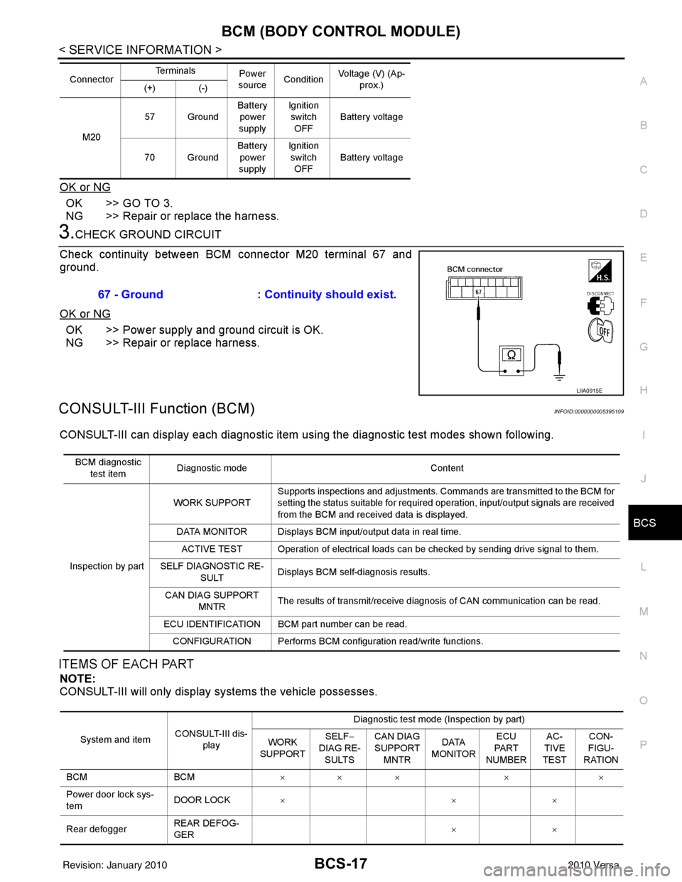
Check continuity between BCM connector M20 terminal 67 and
ground.
OK or NG
OK >> Power supply and ground circuit is OK.
NG >> Repair or replace harness.
CONSULT-III Function (BCM)INFOID:0000000005395109
CONSULT-III can display each diagnostic item using the diagnostic test modes shown following.
ITEMS OF EACH PART
NOTE:
CONSULT-III will only display systems the vehicle possesses.
M20 57 Ground
Battery
power
supply Ignition
switch
OFF Battery voltage
70 Ground Battery
power
supply Ignition
switch OFF Battery voltage
Connector
Te r m i n a l s
Power
source Condition Voltage (V) (Ap-
prox.)
(+) (-)
67 - Ground : Continuity should exist.
LIIA0915E
BCM diagnostic
test item Diagnostic mode
Content
Inspection by part WORK SUPPORT
Supports inspections and adjustments. Commands are transmitted to the BCM for
setting the status suitable for required operation, input/output signals are received
from the BCM and received data is displayed.
DATA MONITOR Displays BCM input/output data in real time. ACTIVE TEST Operation of electrical loads can be checked by sending drive signal to them.
SELF DIAGNOSTIC RE- SULT Displays BCM self-diagnosis results.
CAN DIAG SUPPORT MNTR The results of transmit/receive diagnosis of CAN communication can be read.
ECU IDENTIFICATION BCM part number can be read. CONFIGURATION Performs BCM configuration read/write functions.
System and item CONSULT-III dis-
play Diagnostic test mode (Inspection by part)
WORK
SUPPORT SELF
−
DIAG RE-
SULTS CAN DIAG
SUPPORT
MNTR DATA
MONITOR ECU
PA R T
NUMBER AC-
TIVE
TEST CON-
FIGU-
RATION
BCM BCM××× × ×
Power door lock sys-
tem DOOR LOCK
×× ×
Rear defogger REAR DEFOG-
GER ××
Revision: January 20102010 Versa