2010 NISSAN LATIO turn signal
[x] Cancel search: turn signalPage 2836 of 3745
![NISSAN LATIO 2010 Service Repair Manual CAN COMMUNICATION SYSTEMLAN-27
< SERVICE INFORMATION > [CAN]
C
D
E
F
G H
I
J
L
M A
B
LAN
N
O P
CAN Communication Signal ChartINFOID:0000000005395135
Refer to LAN-16, "How to Use CAN Communication Sig NISSAN LATIO 2010 Service Repair Manual CAN COMMUNICATION SYSTEMLAN-27
< SERVICE INFORMATION > [CAN]
C
D
E
F
G H
I
J
L
M A
B
LAN
N
O P
CAN Communication Signal ChartINFOID:0000000005395135
Refer to LAN-16, "How to Use CAN Communication Sig](/manual-img/5/57358/w960_57358-2835.png)
CAN COMMUNICATION SYSTEMLAN-27
< SERVICE INFORMATION > [CAN]
C
D
E
F
G H
I
J
L
M A
B
LAN
N
O P
CAN Communication Signal ChartINFOID:0000000005395135
Refer to LAN-16, "How to Use CAN Communication Signal Chart" for how to use CAN communication signal
chart.
NOTE:
Refer to LAN-22, "
Abbreviation List" for the abbreviations of the connecting units.
T: Transmit R: Receive
Signal name/Connecting unitECM
BCM
EPS
I-KEY M&A
STRG ABS
TCM
*1
TCM
*2
IPDM-E
A/C compressor request signal T R
Accelerator pedal position signal T
R
*3RR
ASCD CRUISE lamp signal T R
ASCD SET lamp signal T R
Closed throttle position signal T R R
Cooling fan motor operation signal T R
Engine coolant temperature signal TR
Engine speed signal TR
R
*3R
Engine status signal T R R R
Fuel consumption monitor signal T R
Malfunction indicator lamp signal TR
Wide open throttle position signal T R R
A/C switch signal R T
Blower fan motor switch signal R T
Buzzer output signal TR
TR
Day time running light request signal
*4TR
Door lock/unlock status signal TR
Door switch signal TR R R
Front wiper request signal T R
High beam request signal TR R
Horn chirp signal T R
Ignition switch signal T R
Low beam request signal T R
Position lights request signal TR R
Rear window defogger switch signal T R
Sleep/wake up signal TRR
R
RT
Theft warning horn request signal T R
Tire pressure signal
*5TR
Trunk open/close status signal TR
Turn indicator signal TR
EPS operation signal TR
EPS warning lamp signal TR
Door lock/unlock/trunk open request signal RT
Hazard request signal RT
Ignition knob switch signal RT
Revision: January 20102010 Versa
Page 2996 of 3745

LT-1
ELECTRICAL
C
DE
F
G H
I
J
L
M
SECTION LT
A
B
LT
N
O P
CONTENTS
LIGHTING SYSTEM
SERVICE INFORMATION .. ..........................3
PRECAUTIONS .............................................. .....3
Precaution for Supplemental Restraint System
(SRS) "AIR BAG" and "SEAT BELT PRE-TEN-
SIONER" ............................................................. ......
3
Precaution Necessary for Steering Wheel Rota-
tion After Battery Disconnect ............................... ......
3
PREPARATION ...................................................5
Special Service Tool ........................................... ......5
HEADLAMP (FOR USA) .....................................6
Component Parts and Harness Connector Loca-
tion ...................................................................... ......
6
System Description ...................................................6
CAN COMMUNICATION SYSTEM DESCRIP-
TION .................................................................... ......
7
Schematic .................................................................8
Wiring Diagram .........................................................9
Terminal and Reference Value for BCM .................12
Terminal and Reference Value for IPDM E/R .........12
How to Perform Trouble Diagnosis .........................13
Preliminary Check ...................................................13
CONSULT-III Function (BCM) .................................13
CONSULT-III Function (IPDM E/R) .........................14
Headlamp High Beam Does Not Illuminate (Both
Sides) .................................................................. ....
16
Headlamp High Beam Does Not Illuminate (One
Side) .................................................................... ....
18
High Beam Indicator Lamp Does Not Illuminate .....19
Headlamp Low Beam Does Not Illuminate (Both
Sides) .................................................................. ....
20
Headlamp Low Beam Does Not Illuminate (One
Side) .................................................................... ....
22
Headlamps Do Not Turn OFF .................................23
Aiming Adjustment ..................................................24
Bulb Replacement ...................................................25
Removal and Installation .........................................26
Disassembly and Assembly ................................ ....26
HEADLAMP (FOR CANADA) - DAYTIME
LIGHT SYSTEM - ..............................................
28
Component Parts and Harness Connector Loca-
tion ....................................................................... ....
28
System Description ..................................................28
CAN Communication System Description ...............30
Schematic ................................................................31
Wiring Diagram - DTRL - .........................................32
Terminal and Reference Value for BCM ..................35
Terminal and Reference Value for IPDM E/R ...... ....35
How to Perform Trouble Diagnosis ..........................36
Preliminary Check ...................................................36
CONSULT-III Function (BCM) .................................36
CONSULT-III Function (IPDM E/R) ..................... ....36
Daytime Light Control Does Not Operate Properly
(High Beam Headlamps Operate Properly) .............
36
Aiming Adjustment ...................................................38
Bulb Replacement ...................................................39
Removal and Installation .........................................40
Disassembly and Assembly .....................................40
FRONT FOG LAMP ..........................................42
Component Parts and Harness Connector Loca-
tion ...........................................................................
42
System Description ..................................................42
CAN Communication System Description ...............43
Wiring Diagram - F/FOG - .......................................44
Terminal and Reference Value for BCM ..................45
Terminal and Reference Value for IPDM E/R ...... ....45
How to Proceed with Trouble Diagnosis ..................46
Preliminary Check ............................................... ....46
CONSULT-III Function (BCM) .................................46
CONSULT-III Function (IPDM E/R) ..................... ....46
Front Fog lamps Do Not Illuminate (Both Sides) .....46
Front Fog Lamp Does Not Illuminate (One Side) ....48
Aiming Adjustment ...................................................49
Bulb Replacement ...................................................50
Removal and Installation .........................................50
TURN SIGNAL AND HAZARD WARNING
LAMPS ..............................................................
51
Revision: January 20102010 Versa
Page 2997 of 3745

LT-2
Component Parts and Harness Connector Loca-
tion ..........................................................................
51
System Description .................................................51
CAN Communication System Description ..............53
Schematic ............................................................ ...54
Wiring Diagram - TURN - ........................................55
Terminal and Reference Value for BCM .................58
How to Proceed with Trouble Diagnosis .................58
Preliminary Check ..................................................59
CONSULT-III Function (BCM) ................................59
Turn Signals Do Not Operate .................................59
Front Turn Signal Lamp Does Not Operate ............59
Rear Turn Signal Lamp Does Not Operate ............60
Hazard Warning Lamp Does Not Operate But
Turn Signal Lamp Operates ...................................
61
Turn Signal Indicator Lamp Does Not Operate ......62
Bulb Replacement for Front Turn Signal Lamp ......62
Bulb Replacement for Rear Turn Signal Lamp .......62
Removal and Installation of Front Turn Signal
Lamp .......................................................................
62
Removal and Installation of Rear Turn Signal
Lamp .......................................................................
62
LIGHTING AND TURN SIGNAL SWITCH .........63
Removal and Installation ..................................... ...63
HAZARD SWITCH .............................................64
Removal and Installation ..................................... ...64
COMBINATION SWITCH ..................................65
Wiring Diagram - COMBSW - .............................. ...65
Combination Switch Reading Function ...................65
Terminal and Reference Value for BCM .................66
CONSULT-III Function (BCM) ................................66
Combination Switch Inspection ..............................66
Removal and Installation ..................................... ...68
STOP LAMP ......................................................69
Wiring Diagram - STOP/L .................................... ...69
Wiring Diagram - STOP/L .......................................70
Bulb Replacement for High-Mounted Stop Lamp ...70
Bulb Replacement for Rear Combination Lamp for
Stop Lamp ..............................................................
71
Removal and Installation of High-Mounted Stop
Lamp .......................................................................
71
Removal and Installation of Rear Combination
Lamp for Stop Lamp ...............................................
72
BACK-UP LAMP ................................................73
Wiring Diagram - BACK/L - .................................. ...73
Bulb Replacement ..................................................73
Removal and Installation ........................................74
PARKING, LICENSE PLATE AND TAIL
LAMPS ...............................................................
75
Component Parts and Harness Connector Loca-
tion ....................................................................... ...
75
System Description .............................................. ...75
CAN Communication System Description ..............76
Schematic ...............................................................77
Wiring Diagram - TAIL/L - .......................................78
Terminal and Reference Value for BCM .............. ...81
Terminal and Reference Value for IPDM E/R .........81
How to Proceed with Trouble Diagnosis .................82
Preliminary Check ...................................................82
CONSULT-III Function (BCM) ............................. ...82
CONSULT-III Function (IPDM E/R) ........................82
Parking, License Plate and Tail Lamps Do Not Il-
luminate ..................................................................
82
Parking, License Plate and Tail Lamps Do Not
Turn OFF (After Approx. 10 Minutes) .....................
85
Bulb Replacement ................................................ ...85
Removal and Installation .........................................86
REAR COMBINATION LAMP ........................ ...88
Component .......................................................... ...88
Bulb Replacement ...................................................88
Removal and Installation .........................................89
Disassembly and Assembly ................................. ...89
INTERIOR LAMP ...............................................91
Map Lamp ............................................................ ...91
Luggage Room Lamp, Hatch Back .........................91
Trunk Room Lamp, Sedan ......................................92
Vanity Mirror Lamp ..................................................92
INTERIOR ROOM LAMP ...................................94
Component Parts and Harness Connector Loca-
tion ....................................................................... ...
94
System Description .................................................94
Schematic ...............................................................98
Wiring Diagram - INT/L - .........................................99
Terminal and Reference Value for BCM ...............103
How to Proceed with Trouble Diagnosis ...............103
Preliminary Check .................................................104
CONSULT-III Function (BCM) ............................. .104
Interior Room Lamp Control Does Not Operate
(With Map Lamp) ..................................................
105
Interior Room Lamp Control Does Not Operate
(Without Map Lamp) .............................................
107
Bulb Replacement .................................................108
Removal and Installation .......................................109
ILLUMINATION .............................................. ..110
System Description .............................................. .110
CAN Communication System Description ............111
Schematic .............................................................112
Wiring Diagram - ILL - ...........................................113
BULB SPECIFICATIONS ............................... ..117
Headlamp ............................................................. .117
Exterior Lamp ........................................................117
Interior Lamp/Illumination ......................................117
Revision: January 20102010 Versa
Page 3001 of 3745

LT-6
< SERVICE INFORMATION >
HEADLAMP (FOR USA)
HEADLAMP (FOR USA)
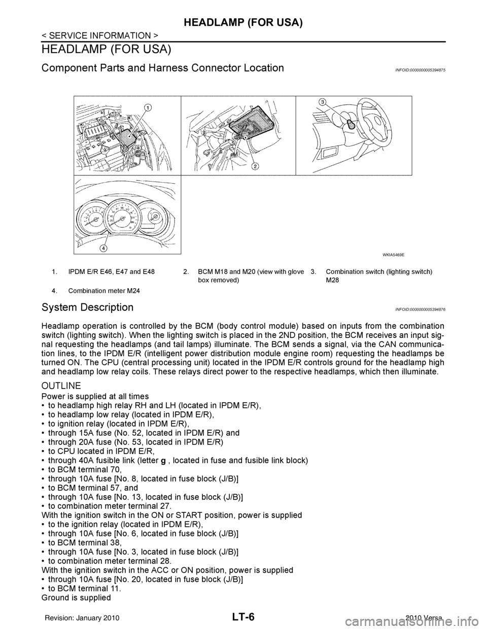
Component Parts and Harness Connector LocationINFOID:0000000005394875
System DescriptionINFOID:0000000005394876
Headlamp operation is controlled by the BCM (body c ontrol module) based on inputs from the combination
switch (lighting switch). When the lighting switch is pl aced in the 2ND position, the BCM receives an input sig-
nal requesting the headlamps (and tail lamps) illuminate. The BCM sends a signal, via the CAN communica-
tion lines, to the IPDM E/R (intelligent power di stribution module engine room) requesting the headlamps be
turned ON. The CPU (central processing unit) located in the IPDM E/R controls ground for the headlamp high
and headlamp low relay coils. These relays direct power to the respective headlamps, which then illuminate.
OUTLINE
Power is supplied at all times
• to headlamp high relay RH and LH (located in IPDM E/R),
• to headlamp low relay (located in IPDM E/R),
• to ignition relay (located in IPDM E/R),
• through 15A fuse (No. 52, located in IPDM E/R) and
• through 20A fuse (No. 53, located in IPDM E/R)
• to CPU located in IPDM E/R,
• through 40A fusible link (letter g , located in fuse and fusible link block)
• to BCM terminal 70,
• through 10A fuse [No. 8, located in fuse block (J/B)]
• to BCM terminal 57, and
• through 10A fuse [No. 13, located in fuse block (J/B)]
• to combination meter terminal 27.
With the ignition switch in the ON or START position, power is supplied
• to the ignition relay (located in IPDM E/R),
• through 10A fuse [No. 6, located in fuse block (J/B)]
• to BCM terminal 38,
• through 10A fuse [No. 3, located in fuse block (J/B)]
• to combination meter terminal 28.
With the ignition switch in the ACC or ON position, power is supplied
• through 10A fuse [No. 20, located in fuse block (J/B)]
• to BCM terminal 11.
Ground is supplied
1. IPDM E/R E46, E47 and E48 2. BCM M18 and M20 (view with glove
box removed)3. Combination switch (lighting switch)
M28
4. Combination meter M24
WKIA5469E
Revision: January 20102010 Versa
Page 3002 of 3745

HEADLAMP (FOR USA)LT-7
< SERVICE INFORMATION >
C
DE
F
G H
I
J
L
M A
B
LT
N
O P
• to BCM terminal 67
• to combination meter terminals 21, 22 and 23
• through grounds M57 and M61, and
• to IPDM E/R terminals 39 and 59
• through grounds E15 and E24.
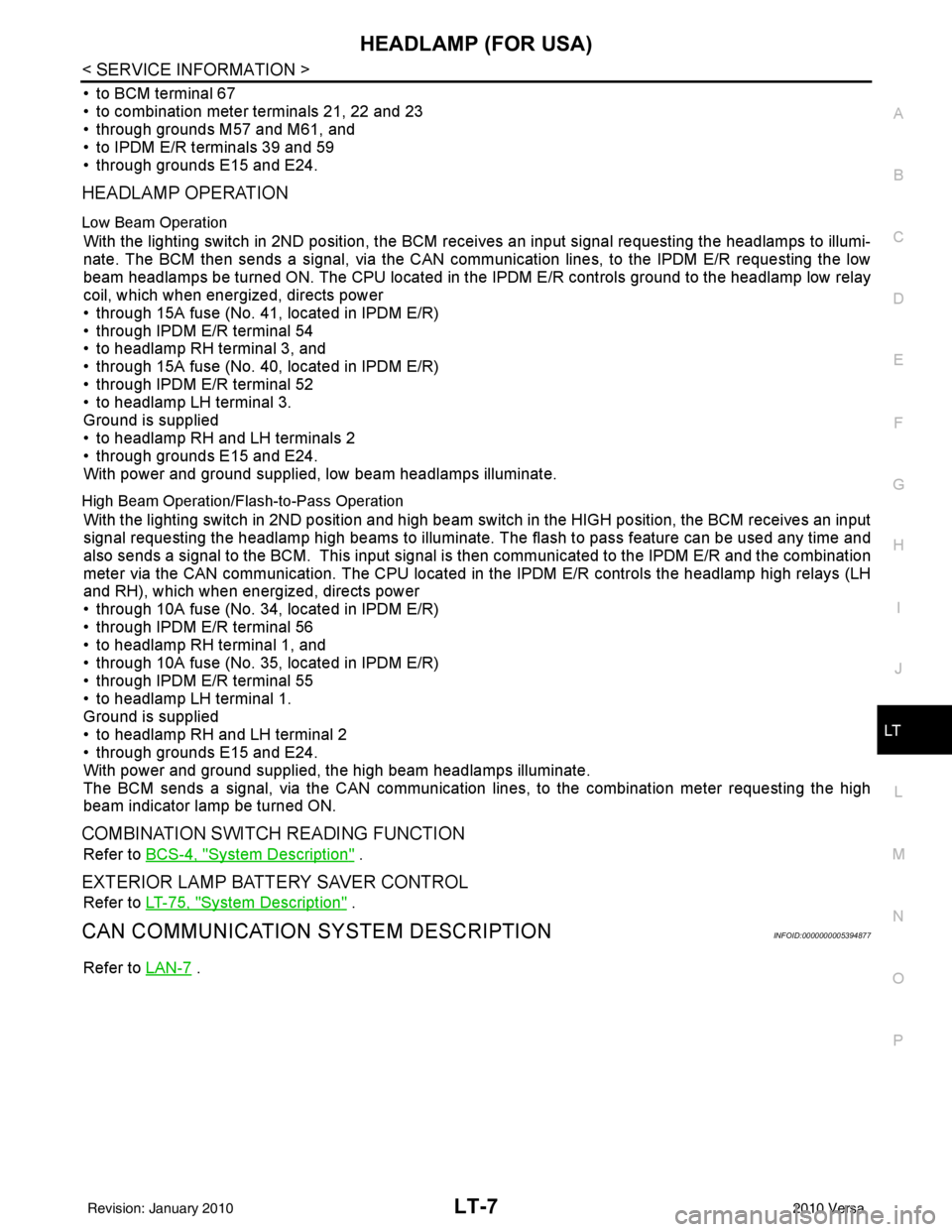
HEADLAMP OPERATION
Low Beam Operation
With the lighting switch in 2ND position, the BCM re ceives an input signal requesting the headlamps to illumi-
nate. The BCM then sends a signal, via the CAN comm unication lines, to the IPDM E/R requesting the low
beam headlamps be turned ON. The CPU located in the IPDM E/R controls ground to the headlamp low relay
coil, which when energized, directs power
• through 15A fuse (No. 41, located in IPDM E/R)
• through IPDM E/R terminal 54
• to headlamp RH terminal 3, and
• through 15A fuse (No. 40, located in IPDM E/R)
• through IPDM E/R terminal 52
• to headlamp LH terminal 3.
Ground is supplied
• to headlamp RH and LH terminals 2
• through grounds E15 and E24.
With power and ground supplied, low beam headlamps illuminate.
High Beam Operation/Flash-to-Pass Operation
With the lighting switch in 2ND position and high beam switch in the HIGH position, the BCM receives an input
signal requesting the headlamp high beams to illuminate. The flash to pass feature can be used any time and
also sends a signal to the BCM. This input signal is then communicated to the IPDM E/R and the combination
meter via the CAN communication. The CPU located in the IPDM E/R controls the headlamp high relays (LH
and RH), which when energized, directs power
• through 10A fuse (No. 34, located in IPDM E/R)
• through IPDM E/R terminal 56
• to headlamp RH terminal 1, and
• through 10A fuse (No. 35, located in IPDM E/R)
• through IPDM E/R terminal 55
• to headlamp LH terminal 1.
Ground is supplied
• to headlamp RH and LH terminal 2
• through grounds E15 and E24.
With power and ground supplied, the high beam headlamps illuminate.
The BCM sends a signal, via the CAN communication lines, to the combination meter requesting the high
beam indicator lamp be turned ON.
COMBINATION SWITCH READING FUNCTION
Refer to BCS-4, "System Description" .
EXTERIOR LAMP BATTERY SAVER CONTROL
Refer to LT-75, "System Description" .
CAN COMMUNICATION SYSTEM DESCRIPTIONINFOID:0000000005394877
Refer to LAN-7 .
Revision: January 20102010 Versa
Page 3009 of 3745

LT-14
< SERVICE INFORMATION >
HEADLAMP (FOR USA)
WORK SUPPORT
Display Item List
CONSULT-III Function (IPDM E/R)INFOID:0000000005612496
CONSULT-III can display each diagnostic item using the diagnostic test modes shown following.
SELF-DIAGNOSTIC RESULTS
Display Item List
Turn signal lamp
Hazard lampFLASHER
××
Blower fan switch sig-
nal
Air conditioner switch
signal AIR CONDITION-
ER
××
Intelligent Key INTELLIGENT
KEY ×
Combination switch COMB SW ×
NVIS (NATS) IMMU ××
Interior lamp battery
saver BATTERY SAV-
ER
××
×
Back door/Trunk TRUNK ××
Theft alarm THEFT ALARM×× ×
Retained accessory
power control RETAINED PWR
×× ×
Oil pressure swit ch SIGNAL BUFFER ××
Low tire pressure moni-
tor AIR PRESSURE
MONITOR
××
× ×
Panic alarm PANIC ALARM ×
System and item
CONSULT-III dis-
play Diagnostic test mode (Inspection by part)
WORK
SUPPORT SELF
−
DIAG RE-
SULTS CAN DIAG
SUPPORT
MNTR DATA
MONITOR ECU
PA R T
NUMBER AC-
TIVE
TEST CON-
FIGU-
RATION
Item Description
RESET SETTING VALUE Return a value set with WORK SUPPORT of each system to a default value in factory shipment.
IPDM E/R diagnostic Mode Description
SELF-DIAG RESULTS Displays IPDM E/R self-diagnosis results. DATA MONITOR Displays IPDM E/R input/output data in real time.
CAN DIAG SUPPORT MNTR The result of transmit/receive diagnosis of CAN communication can be read. ACTIVE TEST Operation of electrical loads can be checked by sending drive signal to them.
Revision: January 20102010 Versa
Page 3011 of 3745

LT-16
< SERVICE INFORMATION >
HEADLAMP (FOR USA)
*1 Perform monitoring of IPDM E/R data with the ignition switch ON. When the ignition switch is in ACC position, display may not be cor-
rect.
*2 This item is displayed, but does not function.
CAN DIAG SUPPORT MNTR
Refer to LAN-9, "Description" .
ACTIVE TEST
Display Item List
Headlamp High Beam Does No t Illuminate (Both Sides)INFOID:0000000005394886
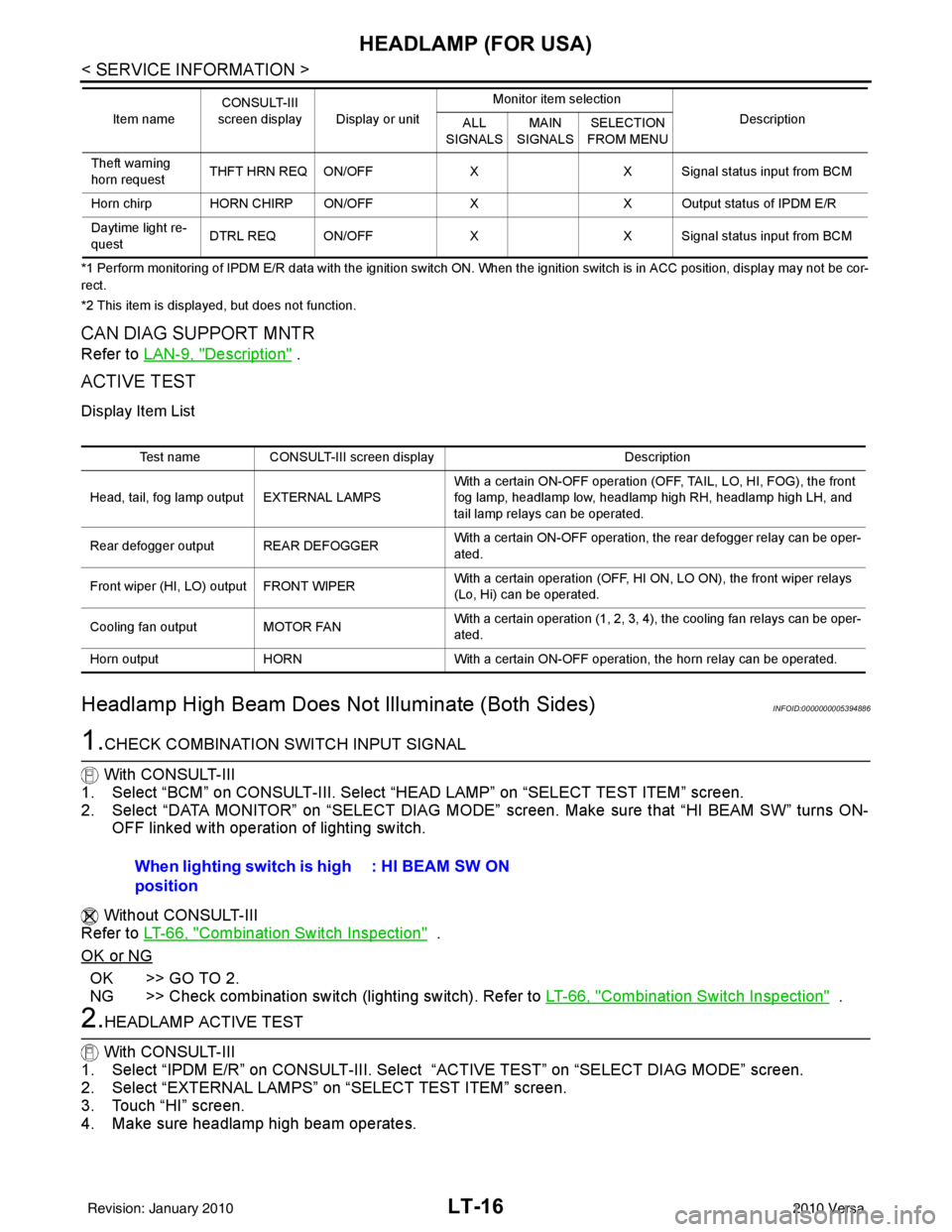
1.CHECK COMBINATION SWITCH INPUT SIGNAL
With CONSULT-III
1. Select “BCM” on CONSULT-III. Select “HEAD LAMP” on “SELECT TEST ITEM” screen.
2. Select “DATA MONITOR” on “SELECT DIAG MODE” screen. Make sure that “HI BEAM SW” turns ON-
OFF linked with operation of lighting switch.
Without CONSULT-III
Refer to LT-66, "
Combination Switch Inspection" .
OK or NG
OK >> GO TO 2.
NG >> Check combination switch (lighting switch). Refer to LT-66, "
Combination Switch Inspection" .
2.HEADLAMP ACTIVE TEST
With CONSULT-III
1. Select “IPDM E/R” on CONSULT-III. Select “ACTIVE TEST” on “SELECT DIAG MODE” screen.
2. Select “EXTERNAL LAMPS” on “SELECT TEST ITEM” screen.
3. Touch “HI” screen.
4. Make sure headlamp high beam operates.
Theft warning
horn request THFT HRN REQ ON/OFF
XX Signal status input from BCM
Horn chirp HORN CHIRP ON/OFF XX Output status of IPDM E/R
Daytime light re-
quest DTRL REQ ON/OFF
XX Signal status input from BCM
Item name
CONSULT-III
screen display Display or unit Monitor item selection
Description
ALL
SIGNALS MAIN
SIGNALS SELECTION
FROM MENU
Test name CONSULT-III screen display Description
Head, tail, fog lamp output EXTERNAL LAMPS With a certain ON-OFF operation (OFF, TAIL, LO, HI, FOG), the front
fog lamp, headlamp low, headlamp high RH, headlamp high LH, and
tail lamp relays can be operated.
Rear defogger output REAR DEFOGGER With a certain ON-OFF operation, the rear defogger relay can be oper-
ated.
Front wiper (HI, LO) output FRONT WIPER With a certain operation (OFF, HI ON, LO ON), the front wiper relays
(Lo, Hi) can be operated.
Cooling fan output MOTOR FAN With a certain operation (1, 2, 3, 4), the cooling fan relays can be oper-
ated.
Horn output HORN With a certain ON-OFF operation, the horn relay can be operated.
When lighting switch is high
position : HI BEAM SW ON
Revision: January 20102010 Versa
Page 3012 of 3745

HEADLAMP (FOR USA)LT-17
< SERVICE INFORMATION >
C
DE
F
G H
I
J
L
M A
B
LT
N
O P
Without CONSULT-III
1. Start auto active test. Refer to PG-20, "
Auto Active Test" .
2. Make sure headlamp high beam operates.
OK or NG
OK >> GO TO 3.
NG >> GO TO 4.
3.CHECK IPDM E/R
1. Select “IPDM E/R” on CONSUL T-III. Select “DATA MONITOR” on “SELECT DIAG MODE” screen.
2. Make sure “HL HI REQ” turns ON when lighting switch is in high position.
OK or NG
OK >> Replace IPDM E/R. Refer to PG-28, "Removal and Installation of IPDM E/R" .
NG >> Replace BCM. Refer to BCS-19, "
Removal and Installation of BCM" .
4.HEADLAMP HIGH BEAM FUSE INSPECTION
Inspect 10A fuse No. 34 (RH) and fuse No. 35 (LH).
OK or NG
OK >> GO TO 5.
NG >> Repair harness.
5.BULB INSPECTION
Inspect inoperative headlamp bulbs.
OK or NG
OK >> GO TO 6.
NG >> Replace headlamp bulb. LT-25, "
Bulb Replacement" .
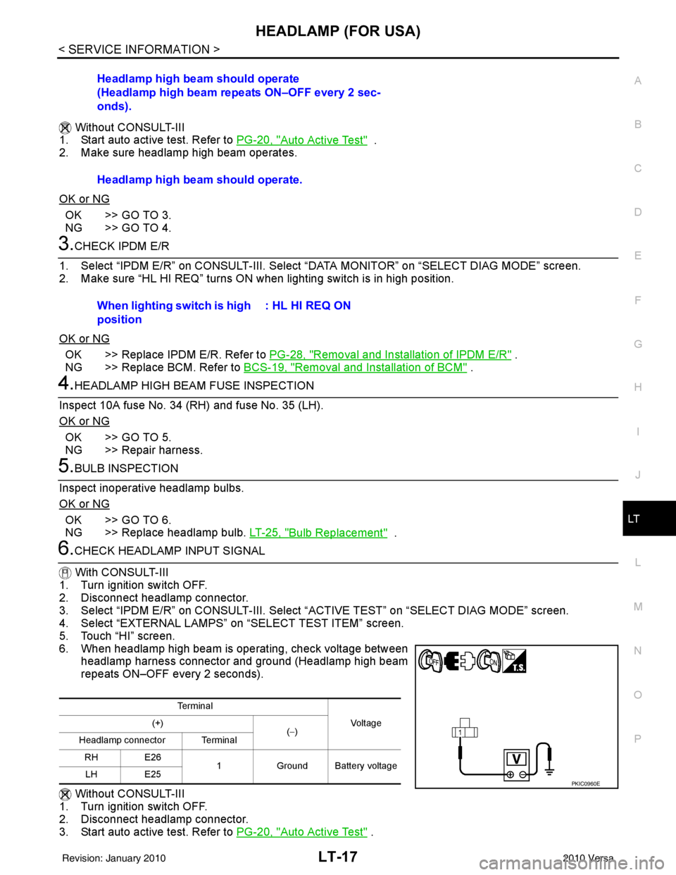
6.CHECK HEADLAMP INPUT SIGNAL
With CONSULT-III
1. Turn ignition switch OFF.
2. Disconnect headlamp connector.
3. Select “IPDM E/R” on CONSUL T-III. Select “ACTIVE TEST” on “SELECT DIAG MODE” screen.
4. Select “EXTERNAL LAMPS” on “SELECT TEST ITEM” screen.
5. Touch “HI” screen.
6. When headlamp high beam is operating, check voltage between headlamp harness connector and ground (Headlamp high beam
repeats ON–OFF every 2 seconds).
Without CONSULT-III
1. Turn ignition switch OFF.
2. Disconnect headlamp connector.
3. Start auto active test. Refer to PG-20, "
Auto Active Test" .
Headlamp high beam should operate
(Headlamp high beam repeats ON–OFF every 2 sec-
onds).
Headlamp high beam should operate.
When lighting switch is high
position
: HL HI REQ ON
Te r m i n a l
Vo l ta g e
(+)
(−)
Headlamp connector Terminal
RH E26 1Ground Battery voltage
LH E25
PKIC0960E
Revision: January 20102010 Versa