2010 NISSAN LATIO turn signal
[x] Cancel search: turn signalPage 2559 of 3745
![NISSAN LATIO 2010 Service Repair Manual EM-200
< SERVICE INFORMATION >[MR18DE]
CYLINDER BLOCK
• The difference (A) between main bearing upper (1) and
main bearing lower (3) shou ld be 0.85 mm (0.033 in) or
less when installing.
• Ensure NISSAN LATIO 2010 Service Repair Manual EM-200
< SERVICE INFORMATION >[MR18DE]
CYLINDER BLOCK
• The difference (A) between main bearing upper (1) and
main bearing lower (3) shou ld be 0.85 mm (0.033 in) or
less when installing.
• Ensure](/manual-img/5/57358/w960_57358-2558.png)
EM-200
< SERVICE INFORMATION >[MR18DE]
CYLINDER BLOCK
• The difference (A) between main bearing upper (1) and
main bearing lower (3) shou ld be 0.85 mm (0.033 in) or
less when installing.
• Ensure the oil holes on cyli nder block and oil holes (A) on
the main bearings (1) are aligned.
6. Install signal plate to crankshaft if removed.
7. Set the signal plate with the flange facing toward the counter weight side (engine front side) to the crank-
shaft rear surface.
8. Apply new engine oil to threads and seat surfaces of bolts.
9. Position crankshaft (2) and signal plate (1) using a dowel pin (service part), and tighten bolts in numerical order as shown.
NOTE:
Dowel pin of crankshaft and signal plate is provided as a set for
each.
10. Tighten bolts in numerical order as shown.
11. Remove dowel pin. (service parts) CAUTION:
Be sure to remove dowel pin.
12. Install crankshaft to cylinder block. • While turning crankshaft by hand, make sure that it turns smoothly.
13. Install main bearing caps referring to the journal No. stamp (A) and front mark (B) as shown.
NOTE:
Main bearing cap cannot be replaced as a single part, because it
is machined together with cylinder block.
14. Apply new engine oil to threads and seat surfaces of bolts.
2 : Cylinder block
4 : Main bearing cap
PBIC3237J
PBIC3236J
A : Dowel pin hole
PBIC3238J
: Engine front
PBIC3239J
Revision: January 20102010 Versa
Page 2739 of 3745

GW-22
< SERVICE INFORMATION >
POWER WINDOW SYSTEM
Then, the motor raises the window until the switch is released.
WINDOW DOWN
When the main power window and door lock/unlock switch (rear LH) is pressed in the down position, power is
supplied
• through main power window and door lock/unlock switch terminal 3
• to rear power window switch LH terminal 3
• through rear power window switch LH terminal 4
• to rear power window motor LH terminal 1.
Ground is supplied
• through main power window and door lock/unlock switch terminal 1
• to rear power window switch LH terminal 2
• through rear power window switch LH terminal 5
• to rear power window motor LH terminal 2.
Then, the motor lowers the window until the switch is released.
When the main power window and door lock/unlock switch (rear RH) is pressed in the down position, power is
supplied
• through main power window and door lock/unlock switch terminal 5
• to rear power window switch RH terminal 3
• through rear power window switch RH terminal 4
• to rear power window motor RH terminal 1.
Ground is supplied
• through main power window and door lock/unlock switch terminal 7
• to rear power window switch RH terminal 2
• through rear power window switch RH terminal 5
• to rear power window motor RH terminal 2.
Then, the motor lowers the window until the switch is released.
AUTO OPERATION
The power window AUTO feature enables the driver to open the window without holding the window switch in
the down position.
POWER WINDOW LOCK
The power window lock is designed to lock operation of all windows except for front door window LH.
When in the lock position, the power window lock di sables power window and door lock/unlock switch RH and
rear power window switch LH and RH by disconnecting switch ground signal. This prevents the power window
motors from operating.
RETAINED POWER OPERATION
When the ignition switch is turned to the OFF position from ON or START position, power is supplied for 45
seconds
• through BCM terminal 68
• to main power window and door lock/unlock switch terminal 10
• to power window and door lock/unlock switch RH terminal 8 and
• to rear power window switches LH and RH terminal 1.
When power and ground are supplied, the BCM conti nues to be energized, and the power window can be
operated.
The retained power operation is canceled when the front LH or front RH door is opened.
Retained power operation period can be changed by CONSULT-III. Refer to GW-30, "
CONSULT-III Function
(BCM)" .
ANTI-PINCH SYSTEM
Main power window and door lock/unlock switch monitors the power window motor operation and the power
window position (full closed or other) for front LH power window by the signal from encoder in front power win-
dow motor LH.
When main power window and door lock/unlock switch detects interruption during the following close opera-
tions
• automatic close operation when igniti on switch is in the ON position
• automatic close operation during retained power operation
Main power window and door lock/unlock switch controls front power window motor LH for open and the
power window will be lowered.
Revision: January 20102010 Versa
Page 2746 of 3745
POWER WINDOW SYSTEMGW-29
< SERVICE INFORMATION >
C
DE
F
G H
J
K L
M A
B
GW
N
O P
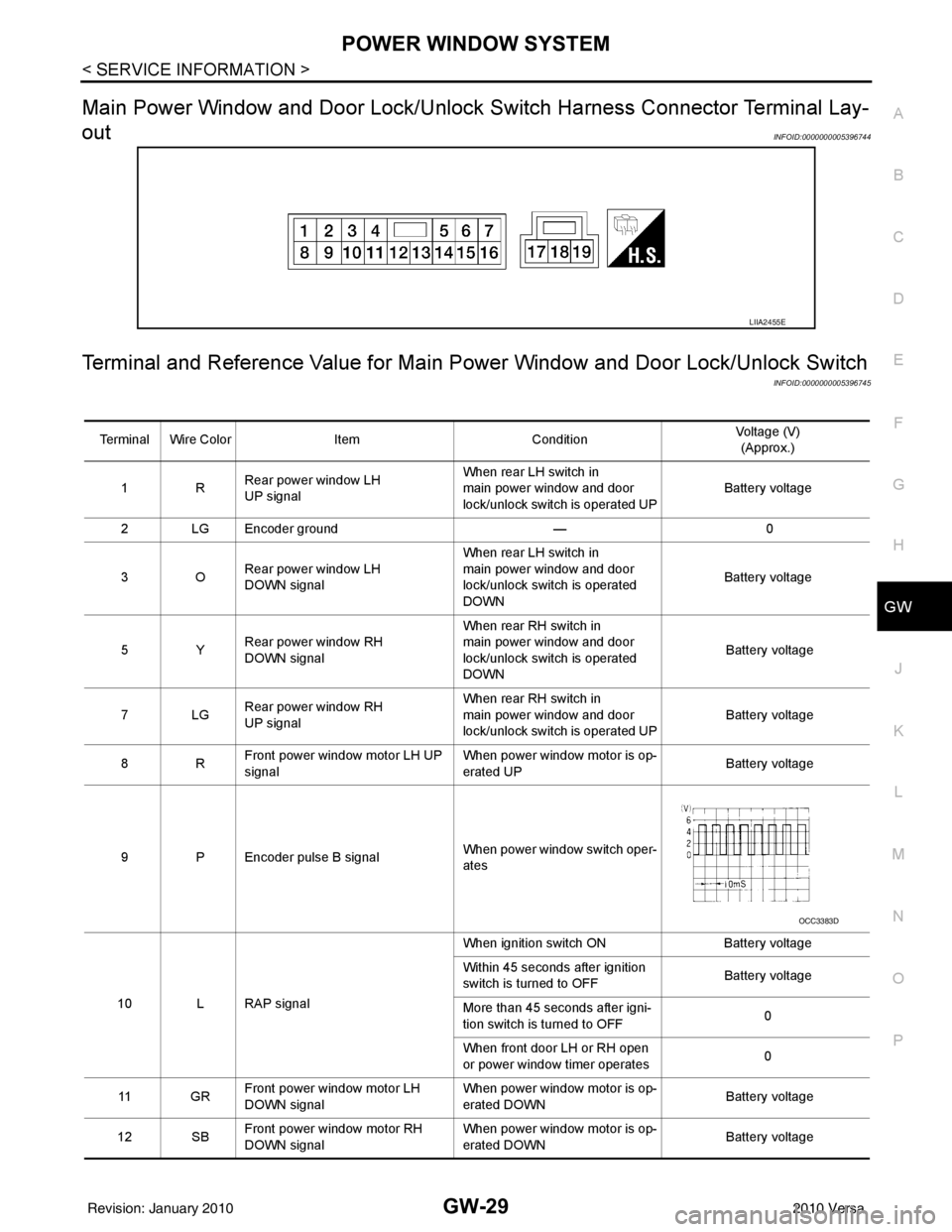
Main Power Window and Door Lock/Unlock Switch Harness Connector Terminal Lay-
out
INFOID:0000000005396744
Terminal and Reference Value for Main Po wer Window and Door Lock/Unlock Switch
INFOID:0000000005396745
LIIA2455E
Terminal Wire ColorItemCondition Voltage (V)
(Approx.)
1R Rear power window LH
UP signal When rear LH switch in
main power window and door
lock/unlock switch is operated UP
Battery voltage
2 LG Encoder ground — 0
3O Rear power window LH
DOWN signal When rear LH switch in
main power window and door
lock/unlock switch is operated
DOWN
Battery voltage
5Y Rear power window RH
DOWN signal When rear RH switch in
main power window and door
lock/unlock switch is operated
DOWN
Battery voltage
7LG Rear power window RH
UP signal When rear RH switch in
main power window and door
lock/unlock switch is operated UP
Battery voltage
8R Front power window motor LH UP
signal When power window motor is op-
erated UP
Battery voltage
9 P Encoder pulse B signal When power window switch oper-
ates
10 L RAP signal When ignition switch ON
Battery voltage
Within 45 seconds after ignition
switch is turned to OFF Battery voltage
More than 45 seconds after igni-
tion switch is turned to OFF 0
When front door LH or RH open
or power window timer operates 0
11 G R Front power window motor LH
DOWN signal When power window motor is op-
erated DOWN
Battery voltage
12 SB Front power window motor RH
DOWN signal When power window motor is op-
erated DOWN
Battery voltage
OCC3383D
Revision: January 20102010 Versa
Page 2748 of 3745
POWER WINDOW SYSTEMGW-31
< SERVICE INFORMATION >
C
DE
F
G H
J
K L
M A
B
GW
N
O P
WORK SUPPORT
DATA MONITOR
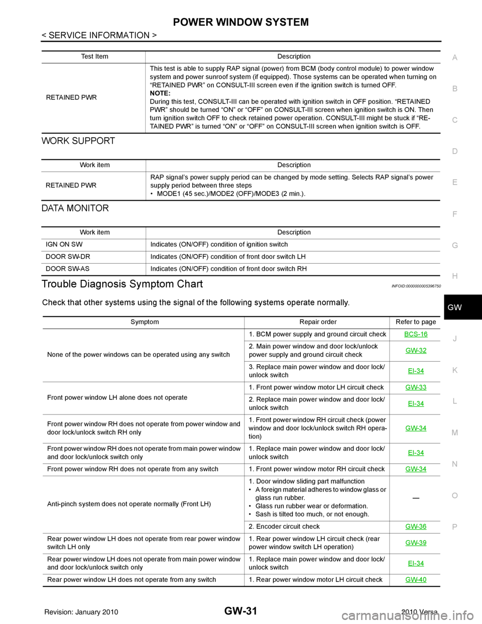
Trouble Diagnosis Symptom ChartINFOID:0000000005396750
Check that other systems us ing the signal of the following systems operate normally.
Test Item Description
RETAINED PWR This test is able to supply RAP signal (powe
r) from BCM (body control module) to power window
system and power sunroof system (if equipped). Those systems can be operated when turning on
“RETAINED PWR” on CONSULT-III screen even if the ignition switch is turned OFF.
NOTE:
During this test, CONSULT-III can be operated with ignition switch in OFF position. “RETAINED
PWR” should be turned “ON” or “OFF” on CONSULT-III screen when ignition switch is ON. Then
turn ignition switch OFF to check retained power operation. CONSULT-III might be stuck if “RE-
TAINED PWR” is turned “ON” or “OFF” on CONSULT-III screen when ignition switch is OFF.
Work item Description
RETAINED PWR RAP signal’s power supply period can be changed by mode setting. Selects RAP signal’s power
supply period between three steps
• MODE1 (45 sec.)/MODE2 (OFF)/MODE3 (2 min.).
Work item
Description
IGN ON SW Indicates (ON/OFF) condition of ignition switch
DOOR SW-DR Indicates (ON/OFF) condition of front door switch LH
DOOR SW-AS Indicates (ON/OFF) condition of front door switch RH
Symptom Repair orderRefer to page
None of the power windows can be operated using any switch 1. BCM power supply and ground circuit check
BCS-16
2. Main power window and door lock/unlock
power supply and ground circuit check GW-32
3. Replace main power window and door lock/
unlock switch EI-34
Front power window LH alone does not operate 1. Front power window motor LH circuit check
GW-332. Replace main power window and door lock/
unlock switch EI-34
Front power window RH does not operate from power window and
door lock/unlock switch RH only 1. Front power window RH circuit check (power
window and door lock/unlock switch RH opera-
tion)
GW-34
Front power window RH does not operate from main power window
and door lock/unlock switch only
1. Replace main power window and door lock/
unlock switch
EI-34
Front power window RH does not operate from any switch 1. Front power window motor RH circuit check
GW-34
Anti-pinch system does not operate normally (Front LH)1. Door window sliding part malfunction
• A foreign material adheres to window glass or
glass run rubber.
• Glass run rubber wear or deformation.
• Sash is tilted too much, or not enough. —
2. Encoder circuit check GW-36
Rear power window LH does not operate from rear power window
switch LH only 1. Rear power window LH circuit check (rear
power window switch LH operation)
GW-39
Rear power window LH does not operate from main power window
and door lock/unlock switch only 1. Replace main power window and door lock/
unlock switch
EI-34
Rear power window LH does not operate from any switch 1. Rear power window motor LH circuit check
GW-40
Revision: January 20102010 Versa
Page 2750 of 3745
POWER WINDOW SYSTEMGW-33
< SERVICE INFORMATION >
C
DE
F
G H
J
K L
M A
B
GW
N
O P
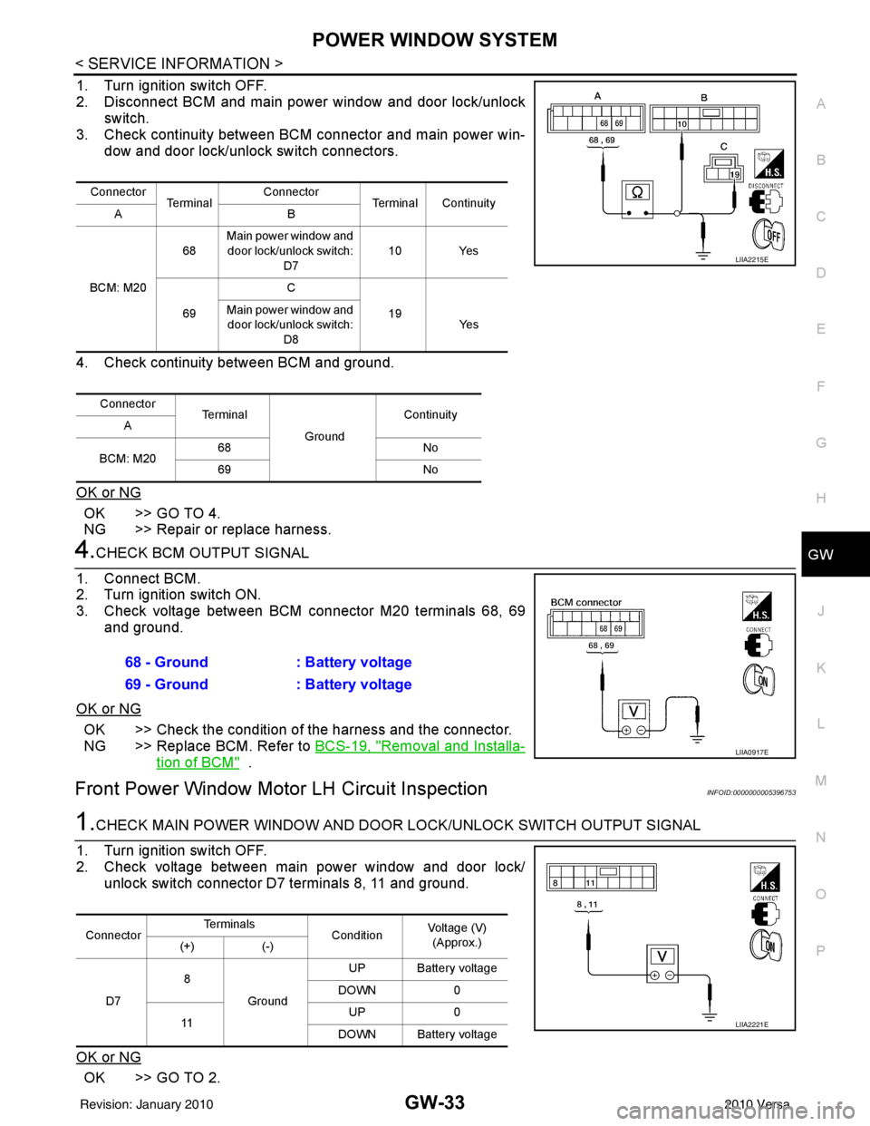
1. Turn ignition switch OFF.
2. Disconnect BCM and main power window and door lock/unlock
switch.
3. Check continuity between BCM connector and main power win- dow and door lock/unlock switch connectors.
4. Check continuity between BCM and ground.
OK or NG
OK >> GO TO 4.
NG >> Repair or replace harness.
4.CHECK BCM OUTPUT SIGNAL
1. Connect BCM.
2. Turn ignition switch ON.
3. Check voltage between BCM connector M20 terminals 68, 69 and ground.
OK or NG
OK >> Check the condition of the harness and the connector.
NG >> Replace BCM. Refer to BCS-19, "
Removal and Installa-
tion of BCM" .
Front Power Window Motor LH Circuit InspectionINFOID:0000000005396753
1.CHECK MAIN POWER WINDOW AND DOOR LOCK/UNLOCK SWITCH OUTPUT SIGNAL
1. Turn ignition switch OFF.
2. Check voltage between main power window and door lock/ unlock switch connector D7 terminals 8, 11 and ground.
OK or NG
OK >> GO TO 2.
Connector Te r m i n a l Connector
Terminal Continuity
AB
BCM: M20 68
Main power window and
door lock/unlock switch: D7 10 Yes
69 C
19
Main power window and
door lock/unlock switch:
D8 Ye s
Connector Te r m i n a l
GroundContinuity
A
BCM: M20 68
No
69 No
LIIA2215E
68 - Ground: Battery voltage
69 - Ground : Battery voltage
LIIA0917E
ConnectorTe r m i n a l s
ConditionVoltage (V)
(Approx.)
(+) (-)
D7 8
Ground UP Battery voltage
DOWN 0
11 UP
0
DOWN Battery voltage
LIIA2221E
Revision: January 20102010 Versa
Page 2751 of 3745
GW-34
< SERVICE INFORMATION >
POWER WINDOW SYSTEM
NG >> Replace main power window and door lock/unlock switch. Refer to EI-34, "Removal and Installa-
tion" .
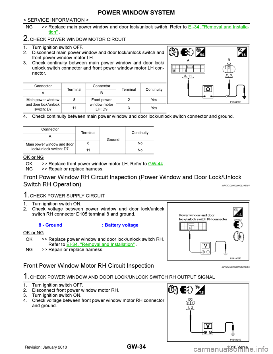
2.CHECK POWER WINDOW MOTOR CIRCUIT
1. Turn ignition switch OFF.
2. Disconnect main power window and door lock/unlock switch and front power window motor LH.
3. Check continuity between main power window and door lock/ unlock switch connector and front power window motor LH con-
nector.
4. Check continuity between main power window and door lock/unlock switch connector and ground.
OK or NG
OK >> Replace front power window motor LH. Refer to GW-44 .
NG >> Repair or replace harness.
Front Power Window RH Circuit Inspecti on (Power Window and Door Lock/Unlock
Switch RH Operation)
INFOID:0000000005396754
1.CHECK POWER SUPPLY CIRCUIT
1. Turn ignition switch ON.
2. Check voltage between power window and door lock/unlock switch RH connector D105 terminal 8 and ground.
OK or NG
OK >> Replace power window and door lock/unlock switch RH. Refer to EI-34, "
Removal and Installation" .
NG >> Repair or replace harness.
Front Power Window Moto r RH Circuit InspectionINFOID:0000000005396755
1.CHECK POWER WINDOW AND DOOR LOCK /UNLOCK SWITCH RH OUTPUT SIGNAL
1. Turn ignition switch OFF.
2. Disconnect front power window motor RH.
3. Turn ignition switch ON.
4. Check voltage between front power window motor RH connector and ground.
Connector Te r m i n a lConnector
Terminal Continuity
AB
Main power window
and door lock/unlock switch: D7 8 Front power
window motor LH: D9 2Y
es
11 3Ye s
Connector Terminal
GroundContinuity
A
Main power window and door lock/unlock switch: D7 8N
o
11 N o
PIIB6430E
8 - Ground: Battery voltage
LIIA1976E
PIIB6431E
Revision: January 20102010 Versa
Page 2754 of 3745
POWER WINDOW SYSTEMGW-37
< SERVICE INFORMATION >
C
DE
F
G H
J
K L
M A
B
GW
N
O P
OK or NG
OK >> Replace main power window and door lock/unlock switch. Refer to EI-34, "Removal and Installa-
tion" .
NG >> Repair or replace harness.
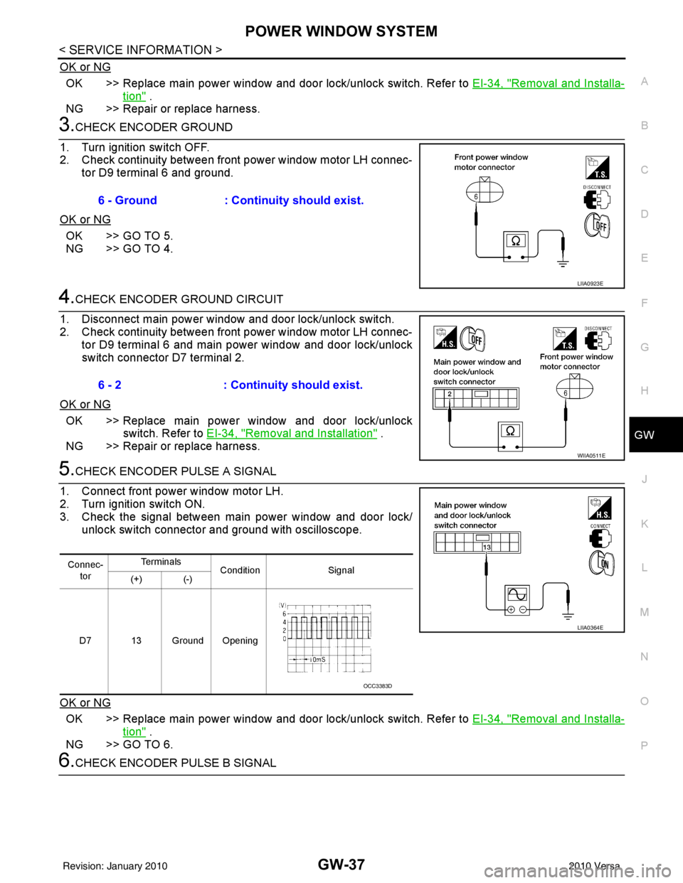
3.CHECK ENCODER GROUND
1. Turn ignition switch OFF.
2. Check continuity between front power window motor LH connec- tor D9 terminal 6 and ground.
OK or NG
OK >> GO TO 5.
NG >> GO TO 4.
4.CHECK ENCODER GROUND CIRCUIT
1. Disconnect main power window and door lock/unlock switch.
2. Check continuity between front power window motor LH connec- tor D9 terminal 6 and main power window and door lock/unlock
switch connector D7 terminal 2.
OK or NG
OK >> Replace main power window and door lock/unlock switch. Refer to EI-34, "
Removal and Installation" .
NG >> Repair or replace harness.
5.CHECK ENCODER PULSE A SIGNAL
1. Connect front power window motor LH.
2. Turn ignition switch ON.
3. Check the signal between main power window and door lock/ unlock switch connector and ground with oscilloscope.
OK or NG
OK >> Replace main power window and door lock/unlock switch. Refer to EI-34, "Removal and Installa-
tion" .
NG >> GO TO 6.
6.CHECK ENCODER PULSE B SIGNAL 6 - Ground
: Continuity should exist.
LIIA0923E
6 - 2: Continuity should exist.
WIIA0511E
Connec-
tor Te r m i n a l s
Condition Signal
(+) (-)
D7 13 Ground Opening
LIIA0364E
OCC3383D
Revision: January 20102010 Versa
Page 2755 of 3745
GW-38
< SERVICE INFORMATION >
POWER WINDOW SYSTEM
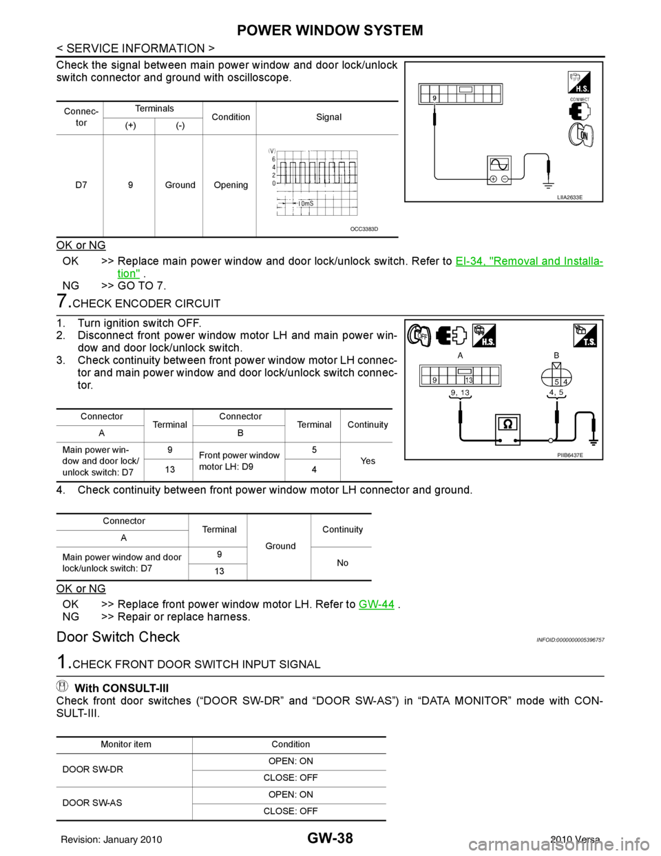
Check the signal between main power window and door lock/unlock
switch connector and ground with oscilloscope.
OK or NG
OK >> Replace main power window and door lock/unlock switch. Refer to EI-34, "Removal and Installa-
tion" .
NG >> GO TO 7.
7.CHECK ENCODER CIRCUIT
1. Turn ignition switch OFF.
2. Disconnect front power window motor LH and main power win- dow and door lock/unlock switch.
3. Check continuity between front power window motor LH connec-
tor and main power window and door lock/unlock switch connec-
tor.
4. Check continuity between front power window motor LH connector and ground.
OK or NG
OK >> Replace front power window motor LH. Refer to GW-44 .
NG >> Repair or replace harness.
Door Switch CheckINFOID:0000000005396757
1.CHECK FRONT DOOR SWITCH INPUT SIGNAL
With CONSULT-III
Check front door switches (“DOOR SW-DR” and “D OOR SW-AS”) in “DATA MONITOR” mode with CON-
SULT-III.
Connec-
tor Te r m i n a l s
Condition Signal
(+) (-)
D7 9 Ground Opening
LIIA2633E
OCC3383D
Connector Te r m i n a lConnector
Terminal Continuity
AB
Main power win-
dow and door lock/
unlock switch: D7 9
Front power window
motor LH: D9 5
Ye s
13 4
Connector Te r m i n a l
GroundContinuity
A
Main power window and door
lock/unlock switch: D7 9
No
13
PIIB6437E
Monitor item Condition
DOOR SW-DR OPEN: ON
CLOSE: OFF
DOOR SW-AS OPEN: ON
CLOSE: OFF
Revision: January 20102010 Versa