Page 2687 of 3745
HOW TO USE THIS MANUALGI-21
< SERVICE INFORMATION >
C
DE
F
G H
I
J
K L
M B
GI
N
O PFR, RR Front, RearLH, RH Left-Hand, Right-Hand M/T Manual Transaxle/Transmission
OD Overdrive
P/S Power Steering
SAE Society of Automotive Engineers, Inc.
SDS Service Data and Specifications
SST Special Service Tools
2WD 2-Wheel Drive
2
22nd range Second [Gear (2GR)]
2
12nd range First [Gear (1GR)]
1
21st range Second [Gear (2GR)]
1
11st range First [Gear (1GR)]
ABBREVIATION
DESCRIPTION
Revision: January 20102010 Versa
Page 2691 of 3745

SERVICE INFORMATION FOR ELECTRICAL INCIDENTGI-25
< SERVICE INFORMATION >
C
DE
F
G H
I
J
K L
M B
GI
N
O P
How to Perform Efficient Diagnos is for an Electrical IncidentINFOID:0000000005399852
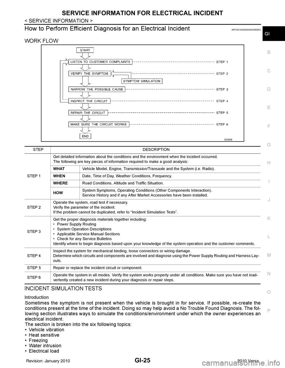
WORK FLOW
INCIDENT SIMULATION TESTS
Introduction
Sometimes the symptom is not present when the vehicle is brought in for service. If possible, re-create the
conditions present at the time of the incident. Doi ng so may help avoid a No Trouble Found Diagnosis. The fol-
lowing section illustrates ways to simulate the c onditions/environment under which the owner experiences an
electrical incident.
The section is broken into the six following topics:
• Vehicle vibration
• Heat sensitive
• Freezing
• Water intrusion
• Electrical load
SGI838
STEP DESCRIPTION
STEP 1 Get detailed information about the conditions and the environment when the incident occurred.
The following are key pieces of information required to make a good analysis:
WHAT
Vehicle Model, Engine, Transmission/Transaxle and the System (i.e. Radio).
WHEN Date, Time of Day, Weather Conditions, Frequency.
WHERE Road Conditions, Altitude and Traffic Situation.
HOW System Symptoms, Operating Conditions (Other Components Interaction).
Service History and if any After Market Accessories have been installed.
STEP 2 Operate the system, road test if necessary.
Verify the parameter of the incident.
If the problem cannot be duplicated, refer to “Incident Simulation Tests”.
STEP 3 Get the proper diagnosis materials together including:
• Power Supply Routing
• System Operation Descriptions
• Applicable Service Manual Sections
• Check for any Service Bulletins
Identify where to begin diagnosis based upon your knowledge of the system operation and the customer comments.
STEP 4 Inspect the system for mechanical binding, loose connectors or wiring damage.
Determine which circuits and components are involved and diagnose using the Power Supply Routing and Harness Lay-
outs.
STEP 5 Repair or replace the incident circuit or component.
STEP 6 Operate the system in all modes. Verify the system works properly under all conditions. Make sure you have not inad-
vertently created a new incident during your diagnosis or repair steps.
Revision: January 20102010 Versa
Page 2701 of 3745

CONSULT-III CHECKING SYSTEMGI-35
< SERVICE INFORMATION >
C
DE
F
G H
I
J
K L
M B
GI
N
O PCONSULT-III CHECKING SYSTEM
DescriptionINFOID:0000000005399854
• CONSULT-III is a hand-held type tester. When it is connected with a diagnostic connector equipped on the vehicle side, it will communicate with the contro l unit equipped in the vehicle and then enable various kinds
of diagnostic tests.
• Refer to CONSULT-III Operator's Manual for more information.
Function and System ApplicationINFOID:0000000005399855
x: Applicable.
*1: If equipped.
*2: With automatic transmission (A/T).
*3: With continuously variable transmission (CVT). Diagnostic test mode
Function
ENGINE
ABS*
1
AIR BAG EPS
IPDM E/R BCM
METER/M&A
INTELLIGENT KEY*
1
TRANSMISSION*
2
TRANSMISSION*
3
Work Support This mode enables a technician to adjust some devices faster and
more accurately by following indications on CONSULT-III. xx - - - x - - xx
Self Diagnostic Results Self-diagnostic results can be read and erased quickly. x x x x x x x x x x
Data Monitor Input/Output data in the ECU can be read. x x x x x x x x x x
CAN Diagnostic Support
Monitor The communication condition of CAN communication line can be
read.
xx - xxxxxxx
Active Test Diagnostic Test Mode in which CONSULT-III drives actuators apart
from ECU shifting some parameters in a specified range. xx - - xx - x - -
Function Test This mode can show results of self-diagnosis of ECU with either
"OK" or "NG". For engines, more practical tests regarding sensors/
switches and/or actuators are available. xxx - - - - - xx
DTC & SRT Confirmation The results of SRT (System Readiness Test) and the self-diagno-
sis status/result can be confirmed. x- - - - - - -x-
Ecu Identification ECM/ECU part number can be read. x x x x - x - x x x
Configuration Sets control module parameters to match vehicle options. - - - - - x - - - -
Special Function Other results or histories, etc that are recorded in ECU are dis-
played. --x------x
Revision: January 20102010 Versa
Page 2704 of 3745

GI-38
< SERVICE INFORMATION >
LIFTING POINT
LIFTING POINT
Special Service ToolINFOID:0000000005399857
CAUTION:
• Every time the vehicle is lifted up, maintain the complete vehicle curb condition.
• Since the vehicle's center of gravity changes when removing main parts on the front side (engine,
transmission, suspension etc.), support a jack up point on the rear side garage jack with a mission
jack or equivalent.
• Since the vehicle's center of gravity changes when removing main parts on the rear side (rear axle,
suspension, etc.), support a jack up point on the front side garage jack with a mission jack or equiv-
alent.
• Be careful not to smash or do not do an ything that would affect piping parts.
Garage Jack and Safety Stand and 2-Pole LiftINFOID:0000000005399858
WARNING:
• Park the vehicle on a level surface when using the jack. Make sure to avoid damaging pipes, tubes,
etc. under the vehicle.
• Never get under the vehicle while it is supported only by the jack. Always use safety stands when you have to get under the vehicle.
• Place wheel chocks at both front an d back of the wheels on the ground.
• When lifting the vehicle, open the lift arms as wid e as possible and ensure that the front and rear of
the vehicle are well balanced.
• When setting the lift arm, do not allow the arm to contact the brake tubes, brake cable, fuel lines and
sill spoiler.
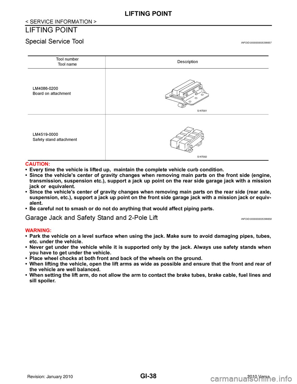
Tool number
Tool name Description
LM4086-0200
Board on attachment
LM4519-0000
Safety stand attachment
S-NT001
S-NT002
Revision: January 20102010 Versa
Page 2706 of 3745

GI-40
< SERVICE INFORMATION >
TOW TRUCK TOWING
TOW TRUCK TOWING
Tow Truck TowingINFOID:0000000005399860
CAUTION:
• All applicable local laws regarding the towing operation must be obeyed.
• It is necessary to use proper towi ng equipment to avoid possible damage to the vehicle during tow-
ing operation. To wing is in accordance with Towing Procedure Manual at dealer.
• Always attach safety chains before towing.
• When towing, make sure that the transmission, steering system and power train are in good order. If
any unit is damaged, dollies must be used.
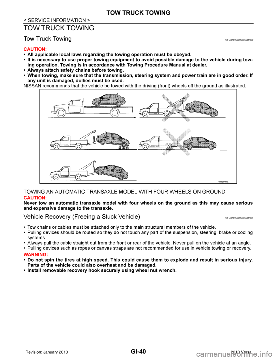
NISSAN recommends that the vehicle be towed with the driving (front) wheels off the ground as illustrated.
TOWING AN AUTOMATIC TRANSAXLE MODEL WITH FOUR WHEELS ON GROUND
CAUTION:
Never tow an automatic transaxle model with four wheels on the ground as this may cause serious
and expensive damage to the transaxle.
Vehicle Recovery (Freeing a Stuck Vehicle)INFOID:0000000005399861
• Tow chains or cables must be attached only to the main structural members of the vehicle.
• Pulling devices should be routed so they do not touch any part of the suspension, steering, brake or cooling
systems.
• Always pull the cable straight out from the front or r ear of the vehicle. Never pull on the vehicle at an angle.
• Pulling devices such as ropes or canvas straps are not recommended for use in vehicle towing or recovery.
WARNING:
• Do not spin the tires at high sp eed. This could cause them to explode and result in serious injury.
Parts of the vehicle could also overheat and be damaged.
• Install removable recovery hook securely using wheel nut wrench.
PIIB6801E
Revision: January 20102010 Versa
Page 2708 of 3745

GI-42
< SERVICE INFORMATION >
RECOMMENDED CHEMICAL PRODUCTS AND SEALANTS
RECOMMENDED CHEMICAL PRODUCTS AND SEALANTS
Recommended Chemical Product and SealantINFOID:0000000005399863
Refer to the following chart for help in selecting the appropriate chemical product or sealant.
Product Description PurposeNissan North America
Part No. (USA) Nissan Canada Part
No. (Canada) Aftermarket Cross-
reference Part Nos.
1 Rear View Mirror Adhe-
sive Used to permanently re-
mount rear view mirrors to
windows.
999MP-AM000P 99998-50505
Permatex 81844
2 Anaerobic Liquid Gas-
ket For metal-to-metal flange
sealing.
Can fill a 0.38 mm (0.015
inch) gap and provide in-
stant sealing for most pow-
ertrain applications.
999MP-AM001P 99998-50503
Permatex 51813 and
51817
3 High Performance
Thread Sealant Provides instant sealing on
any threaded straight or
parallel threaded fitting.
(Thread sealant only, no
locking ability.)
• Do not use on plastic.
999MP-AM002P 999MP-AM002P Permatex 56521
4 Silicone RTV Gasket Maker
999MP-AM003P
(Ultra Grey)99998-50506
(Ultra Grey)Permatex Ultra Grey
82194;
Three Bond
1207,1215, 1216,
1217F, 1217G and
1217H
Nissan RTV Part No.
999MP-A7007
Gasket Maker for Maxima/
Quest 5-speed automatic
transmission
(RE5F22A) ––
Three Bond 1281B
or exact equivalent in
its quality
5 High Temperature,
High Strength Thread
Locking Sealant (Red)
Threadlocker
999MP-AM004P 999MP-AM004P Permatex 27200;
Three Bond 1360,
1360N, 1305 N&P,
1307N, 1335,
1335B, 1363B,
1377C, 1386B, D&E
and 1388
Loctite 648
6 Medium Strength
Thread Locking Seal-
ant (Blue) Threadlocker (service tool
removable)
999MP-AM005P 999MP-AM005P Permatex 24200,
24206, 24240,
24283 and 09178;
Three Bond 1322,
1322N, 1324 D&N,
1333D, 1361C,
1364D, 1370C and
1374
Revision: January 20102010 Versa
Page 2709 of 3745

IDENTIFICATION INFORMATIONGI-43
< SERVICE INFORMATION >
C
DE
F
G H
I
J
K L
M B
GI
N
O PIDENTIFICATION INFORMATION
Model VariationINFOID:0000000005399864
Model code designations:
IDENTIFICATION NUMBER
Body Engine Transmission Grade Destination
USA Canada
Hatchback MR18DE 6 M/T
SFDSALDY-EUA
FDSALDY-ENA
4 A/T FDSALDA-EUAFDSALDA-ENA
6 M/T SL —
FDSALGY-ENA
CVT FDSALGZ-EUAFDSALGZ-ENA
Sedan 6 M/T
SBDSALDY-EUA
—
4 A/T BDSALDA-EUA—
4 A/T SLBDSALGA-EUA —
HR16DE 5 M/T
Base
BDTALAF-EUA BDTALAF-ENA
1.6 L BDTALCF-EUA —
4 A/T 1.6 L
BDTALCA-EUA —
Base —BDTALAA-ENA
Position (Left to Right) Character
Qualifier Definition
1 F Body type F: Hatchback
B: Sedan
2 DS Engine DS: MR18DE
DT: HR16DE
3
4 A Axle A: 2WD model
5 L Handle L: LH drive
6DG ra de A: 1.6 Base
C: 1.6
D: 1.8 S
G: 1.8 SL
7 Y Transmission A: 4 A/T
F: 5 M/T
Y: 6 M/ T
Z: CVT
8 C11 Model C11: Versa
9
10 11 E Intake E: EGI
12 U Zone N: Canada
U: USA
13 A Equipment A: Standard
14
xxxxx Option Codes
15
16
17
18
Revision: January 20102010 Versa
Page 2717 of 3745
TERMINOLOGYGI-51
< SERVICE INFORMATION >
C
DE
F
G H
I
J
K L
M B
GI
N
O P
***: Not applicable Transmission range switch
*** Park/neutral position switch
Transmission control module TCMA/T control unit
Turbocharger TCTurbocharger
Vehicle speed sensor VSSVehicle speed sensor
Volume air flow sensor VAFSAir flow meter
Warm up oxidation catalyst WU-OC Catalyst
Warm up oxidation catalytic converter sys-
tem WU-OC system
***
Warm up three way catalyst WU-TWC Catalyst
Warm up three way catalytic converter sys-
tem WU-TWC system
***
Wide open throttle position switch WOTP switchFull switch
NEW TERM
NEW ACRONYM /
ABBREVIATION OLD TERM
Revision: January 20102010 Versa