Page 3020 of 3745

HEADLAMP (FOR USA)LT-25
< SERVICE INFORMATION >
C
DE
F
G H
I
J
L
M A
B
LT
N
O P
• Aim each headlamp individually and ensure other headlamp beam pattern is blocked from screen.
- For vertical headlamp aiming, adjust headlamp until beam pattern is positioned per specified dimensions.
Bulb ReplacementINFOID:0000000005394893
CAUTION:
After installing bulb, be sure to install plastic cap and bulb socket securely to ensure watertightness.
HEADLAMP (HIGH/LOW)
1. Turn lighting switch OFF.
2. Remove the headlamp. Refer to LT-26, "
Removal and Installation".
3. Remove back cover.
4. Unlock retaining spring and remove bulb from headlamp.
PARKING (CLEARANCE) LAMP
1. Turn lighting switch OFF.
A. Right B. Vertical center line of headlamp C. Horizontal and vertical aiming center
point of headlamp
D. Left E. Vertical aiming cutoff pointF. Cutoff line for vertical aiming evalua-
tion
G. Acceptable vertical cutoff setting at horizontal aiming point H. Horizontal center line of headlamp J. Maximum acceptable vertical aiming
point
K. Minimum acceptable vertical aiming point L. Aiming distance from center of head-
lamp to aiming screen
WKIA4287E
Description Halogen Headlamp
Vertical aiming cutoff point (E) 53.2 mm (2.094 in)
Minimum acceptable vertical aiming point (K) 13.3 mm (0.52 in)
Maximum acceptable vertical aiming point (J) 93.1 mm (3.67 in)
Aiming distance from center of headlamp to aiming screen (L) 7.62 m (25 ft)
Revision: January 20102010 Versa
Page 3021 of 3745
LT-26
< SERVICE INFORMATION >
HEADLAMP (FOR USA)
2. Remove the headlamp. Refer to LT-26, "Removal and Installation".
3. Turn bulb socket counterclockwise and unlock it.
4. Remove bulb from its socket.
FRONT TURN SIGNAL LAMP
1. Turn lighting switch OFF.
2. Remove the headlamp. Refer to LT-26, "
Removal and Installation".
3. Turn bulb socket counterclockwise and unlock it.
4. Remove bulb from its socket.
Removal and InstallationINFOID:0000000005394894
REMOVAL
1. Disconnect the negative battery terminal.
2. Remove front bumper fascia. Refer to EI-15
.
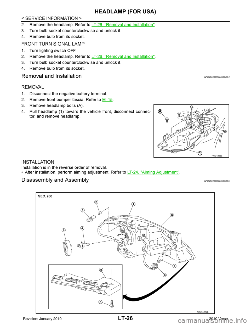
3. Remove headlamp bolts (A).
4. Pull headlamp (1) toward the vehicle front, disconnect connec- tor, and remove headlamp.
INSTALLATION
Installation is in the reverse order of removal.
• After installation, perform aiming adjustment. Refer to LT-24, "
Aiming Adjustment".
Disassembly and AssemblyINFOID:0000000005394895
PKIC1223E
WKIA5418E
Revision: January 20102010 Versa
Page 3022 of 3745
HEADLAMP (FOR USA)LT-27
< SERVICE INFORMATION >
C
DE
F
G H
I
J
L
M A
B
LT
N
O P
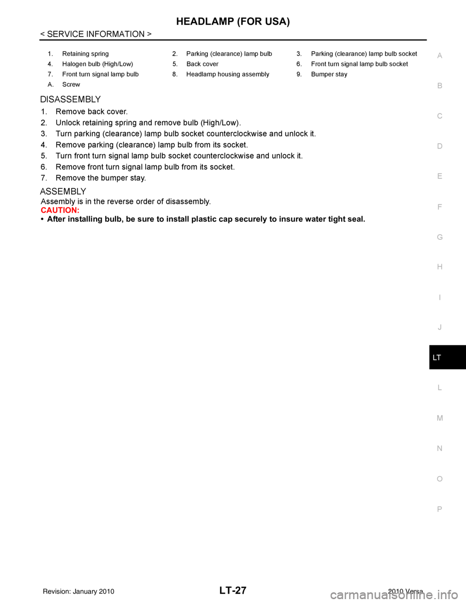
DISASSEMBLY
1. Remove back cover.
2. Unlock retaining spring and remove bulb (High/Low).
3. Turn parking (clearance) lamp bulb socket counterclockwise and unlock it.
4. Remove parking (clearance) lamp bulb from its socket.
5. Turn front turn signal lamp bulb socket counterclockwise and unlock it.
6. Remove front turn signal lamp bulb from its socket.
7. Remove the bumper stay.
ASSEMBLY
Assembly is in the reverse order of disassembly.
CAUTION:
• After installing bulb, be sure to install plastic cap securely to insure water tight seal.
1. Retaining spring 2. Parking (clearance) lamp bulb 3. Parking (clearance) lamp bulb socket
4. Halogen bulb (High/Low) 5. Back cover6. Front turn signal lamp bulb socket
7. Front turn signal lamp bulb 8. Headlamp housing assembly 9. Bumper stay
A. Screw
Revision: January 20102010 Versa
Page 3034 of 3745

HEADLAMP (FOR CANADA) - DAYTIME LIGHT SYSTEM -
LT-39
< SERVICE INFORMATION >
C
D E
F
G H
I
J
L
M A
B
LT
N
O P
• Aim each headlamp individually and ensure other headlamp beam pattern is blocked from screen.
- For vertical headlamp aiming, adjust headlamp until beam pattern is positioned per specified dimensions.
Bulb ReplacementINFOID:0000000005394909
CAUTION:
After installing bulb, be sure to install plastic cap and bulb socket securely to ensure watertightness.
HEADLAMP (HIGH/LOW)
1. Turn lighting switch OFF.
2. Remove the headlamp. Refer to LT-26, "
Removal and Installation".
3. Remove back cover.
4. Unlock retaining spring and remove bulb from headlamp.
PARKING (CLEARANCE) LAMP
1. Turn lighting switch OFF.
A. Right B. Vertical center line of headlamp C. Horizontal and vertical aiming center
point of headlamp
D. Left E. Vertical aiming cutoff pointF. Cutoff line for vertical aiming evalua-
tion
G. Acceptable vertical cutoff setting at horizontal aiming point H. Horizontal center line of headlamp J. Maximum acceptable vertical aiming
point
K. Minimum acceptable vertical aiming point L. Aiming distance from center of head-
lamp to aiming screen
WKIA4287E
Description Halogen Headlamp
Vertical aiming cutoff point (E) 53.2 mm (2.094 in)
Minimum acceptable vertical aiming point (K) 13.3 mm (0.52 in)
Maximum acceptable vertical aiming point (J) 93.1 mm (3.67 in)
Aiming distance from center of headlamp to aiming screen (L) 7.62 m (25 ft)
Revision: January 20102010 Versa
Page 3035 of 3745
LT-40
< SERVICE INFORMATION >
HEADLAMP (FOR CANADA) - DAYTIME LIGHT SYSTEM -
2. Remove the headlamp. Refer to LT-26, "Removal and Installation".
3. Turn bulb socket counterclockwise and unlock it.
4. Remove bulb from its socket.
FRONT TURN SIGNAL LAMP
1. Turn lighting switch OFF.
2. Remove the headlamp. Refer to LT-26, "
Removal and Installation".
3. Turn bulb socket counterclockwise and unlock it.
4. Remove bulb from its socket.
Removal and InstallationINFOID:0000000005394910
REMOVAL
1. Disconnect the negative battery terminal.
2. Remove front bumper fascia. Refer to EI-15
.
3. Remove headlamp bolts (A).
4. Pull headlamp (1) toward the vehicle front, disconnect connec- tor, and remove headlamp.
INSTALLATION
Installation is in the reverse order of removal.
• After installation, perform aiming adjustment. Refer to LT-38, "
Aiming Adjustment".
Disassembly and AssemblyINFOID:0000000005394911
PKIC1223E
WKIA5418E
Revision: January 20102010 Versa
Page 3036 of 3745
HEADLAMP (FOR CANADA) - DAYTIME LIGHT SYSTEM -
LT-41
< SERVICE INFORMATION >
C
D E
F
G H
I
J
L
M A
B
LT
N
O P
DISASSEMBLY
1. Remove back cover.
2. Unlock retaining spring and remove bulb (High/Low).
3. Turn parking (clearance) lamp bulb socket counterclockwise and unlock it.
4. Remove parking (clearance) lamp bulb from its socket.
5. Turn front turn signal lamp bulb socket counterclockwise and unlock it.
6. Remove front turn signal lamp bulb from its socket.
7. Remove the bumper stay.
ASSEMBLY
Assembly is in the reverse order of disassembly.
CAUTION:
• After installing bulb, be sure to install plastic cap securely to insure water tight seal.
1. Retaining spring 2. Parking (clearance) lamp bulb 3. Parking (clearance) lamp bulb socket
4. Halogen bulb (High/Low) 5. Back cover6. Front turn signal lamp bulb socket
7. Front turn signal lamp bulb 8. Headlamp housing assembly 9. Bumper stay
A. Screw
Revision: January 20102010 Versa
Page 3043 of 3745

LT-48
< SERVICE INFORMATION >
FRONT FOG LAMP
3. Check continuity between IPDM E/R harness connector (A) and
front fog lamp harness connector (B).
OK or NG
OK >> Replace IPDM E/R. Refer to PG-28, "Removal and
Installation of IPDM E/R" .
NG >> Repair harness or connector.
7.CHECK FOG LAMP GROUND
1. Check continuity between front fog lamp harness connector and
ground.
OK or NG
OK >> Check front fog lamp bulbs.
NG >> Repair harness or connector.
Front Fog Lamp Does No t Illuminate (One Side)INFOID:0000000005394923
1. CHECK BULB
Check bulb of lamp which does not illuminate.
OK or NG
OK >> GO TO 2.
NG >> Replace front fog lamp bulb.
2.CHECK FOG LAMP CIRCUIT
1. Turn ignition switch OFF.
2. Disconnect IPDM E/R connector and front fog lamp connector.
3. Check continuity between IPDM E/R harness connector (A) and
front fog lamp harness connector (B).
OK or NG
OK >> GO TO 3.
NG >> Repair harness or connector.
3.CHECK FOG LAMP GROUND
Circuit AB
Continuity
Connector Terminal Connector Terminal
RH E47 51 E28
1Yes
LH 50 E27
WKIA4408E
Front fog lamp connector Terminal
Ground Continuity
RH E28
2Y es
LH E27
PKIA6277E
Circuit AB
Continuity
Connector Terminal Connector Terminal
RH E47 51 E28
1Yes
LH 50 E27
WKIA4408E
Revision: January 20102010 Versa
Page 3044 of 3745
FRONT FOG LAMPLT-49
< SERVICE INFORMATION >
C
DE
F
G H
I
J
L
M A
B
LT
N
O P
1. Check continuity between front fog lamp harness connector and ground.
OK or NG
OK >> Replace IPDM E/R. Refer to PG-28, "Removal and
Installation of IPDM E/R" .
NG >> Repair harness or connector.
Aiming AdjustmentINFOID:0000000005394924
The front fog lamp is a semi-sealed beam type whic h uses a replaceable halogen bulb. Before performing
aiming adjustment, make sure of the following.
• Keep all tires inflated to correct pressure.
• Place vehicle on level surface.
• Set that there is no-load in vehicle other than the driver (or equivalent weight placed in driver’s position). Coolant, engine oil filled up to correct level and full fuel tank, spare tire, jack and tools are properly stowed.
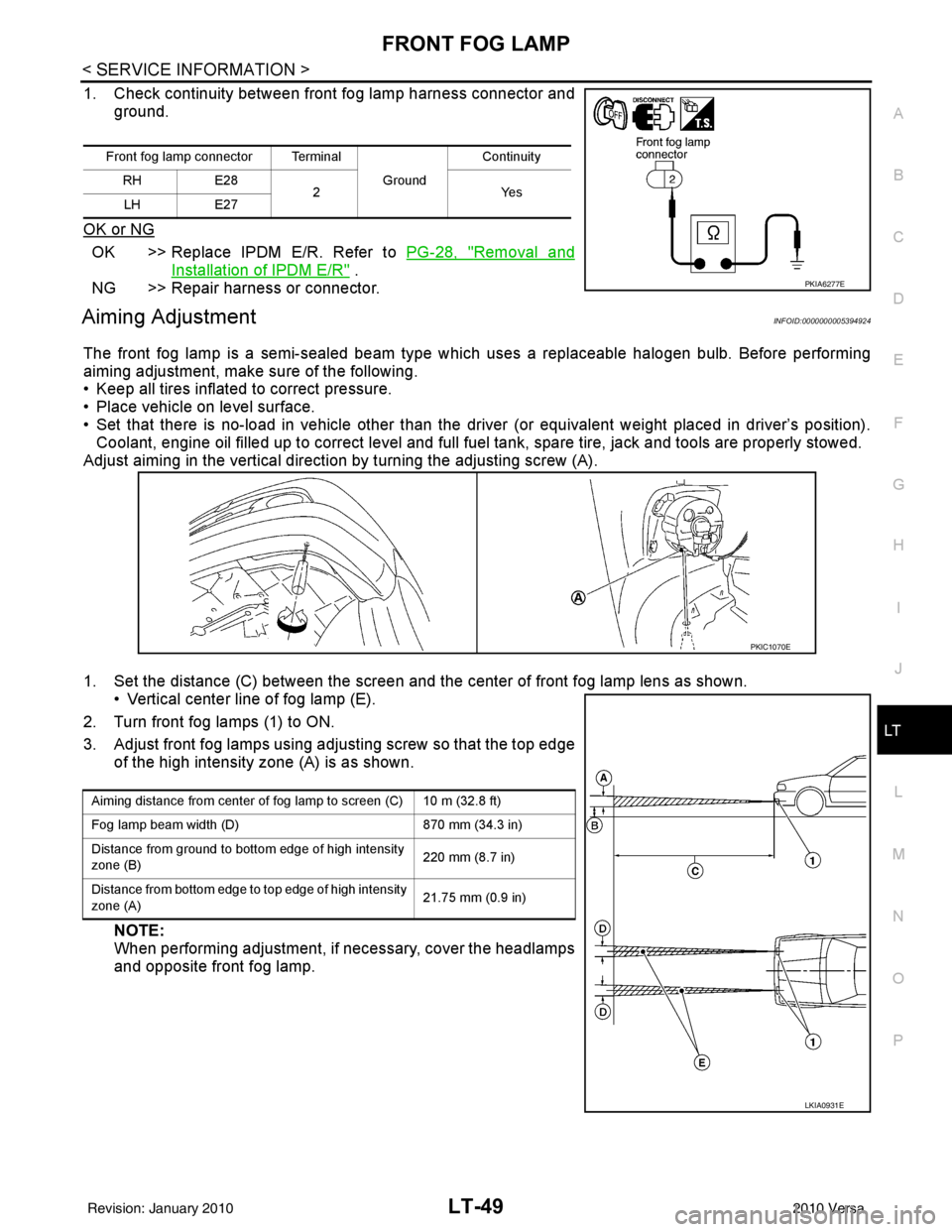
Adjust aiming in the vertical direction by turning the adjusting screw (A).
1. Set the distance (C) between the screen and the c enter of front fog lamp lens as shown.
• Vertical center line of fog lamp (E).
2. Turn front fog lamps (1) to ON.
3. Adjust front fog lamps using adjusting screw so that the top edge of the high intensity zone (A) is as shown.
NOTE:
When performing adjustment, if necessary, cover the headlamps
and opposite front fog lamp.
Front fog lamp connector Terminal
Ground Continuity
RH E28
2Y es
LH E27
PKIA6277E
PKIC1070E
Aiming distance from center of fog lamp to screen (C) 10 m (32.8 ft)
Fog lamp beam width (D) 870 mm (34.3 in)
Distance from ground to bottom edge of high intensity
zone (B) 220 mm (8.7 in)
Distance from bottom edge to top edge of high intensity
zone (A) 21.75 mm (0.9 in)
LKIA0931E
Revision: January 20102010 Versa