Page 2787 of 3745

PRECAUTIONSIP-3
< PRECAUTION >
C
DE
F
G H
J
K L
M A
B
IP
N
O P
5. When the repair work is completed, return the ignition switch to the ″LOCK ″ position before connecting
the battery cables. (At this time, the steering lock mechanism will engage.)
6. Perform a self-diagnosis check of al l control units using CONSULT-III.
PrecautionINFOID:0000000005396850
• Disconnect both battery terminals in advance.
• Disconnect air bag system line in advance.
• Never tamper with or force air bag lid open, as this may adversely affect air bag performance.
• Be careful not to scratch pad and other parts.
• When removing or disassembling any part, be careful not to damage or deform it. Protect parts which may
get in the way with cloth.
• When removing parts, protect parts by wrapping tools with vinyl or tape.
• Keep removed parts protected with cloth.
• If a clip is deformed or damaged, replace it.
• If an non-reusable part is removed, replace it with a new one.
• Tighten bolts and nuts firmly to the specified torque.
• After re-assembly has been completed, make sure each part functions correctly.
• Remove stains in the following way.
Water-soluble stains:
Dip a soft cloth in warm water, and then squeeze it tight ly. After wiping the stain, wipe with a soft dry cloth.
Oil stain:
Dissolve a synthetic detergent in warm water (density of 2 to 3% or less), dip the cloth, then clean off the stain
with the cloth. Next, dip the cloth in fresh water and squeeze it tightly. Then clean off the detergent completely.
Then wipe the area with a soft dry cloth.
• Do not use any organic solvent, such as thinner or benzine.
Revision: January 20102010 Versa
Page 2796 of 3745

IP-12
< ON-VEHICLE REPAIR >
INSTRUMENT PANEL ASSEMBLY
Removal and Installation
INFOID:0000000005396857
INSTRUMENT PANEL ASSEMBLY
Removal
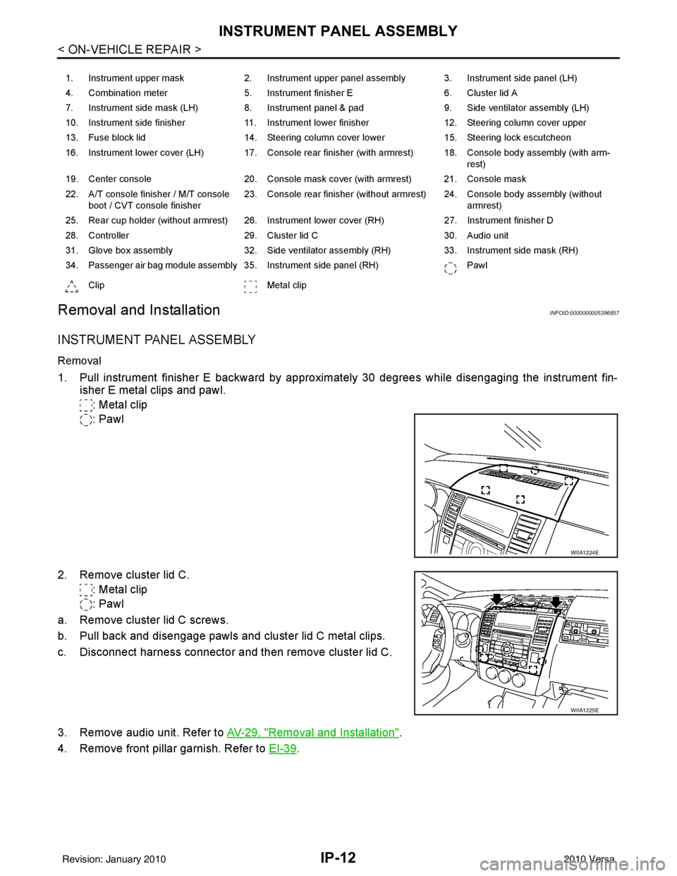
1. Pull instrument finisher E backward by approximately 30 degrees while disengaging the instrument fin- isher E metal clips and pawl.
: Metal clip
: Pawl
2. Remove cluster lid C. : Metal clip
: Pawl
a. Remove cluster lid C screws.
b. Pull back and disengage pawls and cluster lid C metal clips.
c. Disconnect harness connector and then remove cluster lid C.
3. Remove audio unit. Refer to AV-29, "
Removal and Installation".
4. Remove front pillar garnish. Refer to EI-39
.
1. Instrument upper mask 2. Instrument upper panel assembly 3. Instrument side panel (LH)
4. Combination meter 5. Instrument finisher E 6. Cluster lid A
7. Instrument side mask (LH) 8. Instrument panel & pad 9. Side ventilator assembly (LH)
10. Instrument side finisher 11. Instrument lower finisher 12. Steering column cover upper
13. Fuse block lid 14. Steering column cover lower 15. Steering lock escutcheon
16. Instrument lower cover (LH) 17. Console rear finisher (with armrest) 18. Console body assembly (with arm- rest)
19. Center console 20. Console mask cover (with armrest) 21. Console mask
22. A/T console finisher / M/T console boot / CVT console finisher 23. Console rear finisher (without armrest) 24. Console body assembly (without
armrest)
25. Rear cup holder (without armrest) 26. Instrument lower cover (RH) 27. Instrument finisher D
28. Controller 29. Cluster lid C 30. Audio unit
31. Glove box assembly 32. Side ventilator assembly (RH) 33. Instrument side mask (RH)
34. Passenger air bag module assembly 35. Instrument side panel (RH) Pawl
Clip Metal clip
WIIA1224E
WIIA1225E
Revision: January 20102010 Versa
Page 2798 of 3745

IP-14
< ON-VEHICLE REPAIR >
INSTRUMENT PANEL ASSEMBLY
9. Remove steering lock escutcheon.
10. Remove screws, and disengage pawls then remove the steering column cover.
11. Remove cluster lid A.
a. Remove screws from instrument upper panel right side.
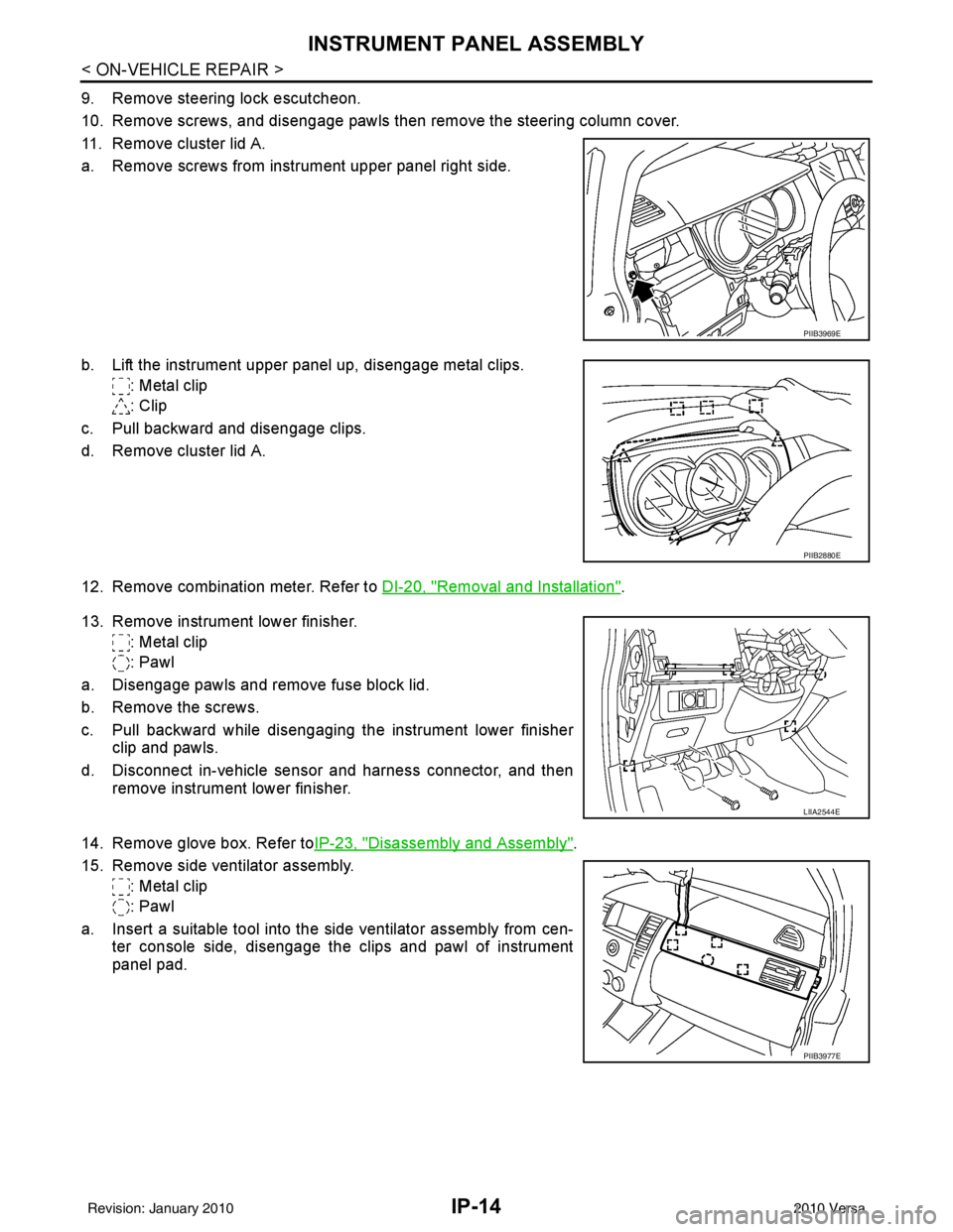
b. Lift the instrument upper panel up, disengage metal clips.: Metal clip
: Clip
c. Pull backward and disengage clips.
d. Remove cluster lid A.
12. Remove combination meter. Refer to DI-20, "
Removal and Installation".
13. Remove instrument lower finisher. : Metal clip
: Pawl
a. Disengage pawls and remove fuse block lid.
b. Remove the screws.
c. Pull backward while disengaging the instrument lower finisher clip and pawls.
d. Disconnect in-vehicle sensor and harness connector, and then remove instrument lower finisher.
14. Remove glove box. Refer to IP-23, "
Disassembly and Assembly".
15. Remove side ventilator assembly. : Metal clip
: Pawl
a. Insert a suitable tool into the side ventilator assembly from cen- ter console side, disengage the clips and pawl of instrument
panel pad.
PIIB3969E
PIIB2880E
LIIA2544E
PIIB3977E
Revision: January 20102010 Versa
Page 2801 of 3745
INSTRUMENT PANEL ASSEMBLYIP-17
< ON-VEHICLE REPAIR >
C
DE
F
G H
J
K L
M A
B
IP
N
O P
5. Insert a remover into upper space of instrument mask. : Pawl
6. Disengage pawls, and then remove instrument side mask.
7. Insert a remover into space of instrument side finisher. : Metal clip
8. Disengage metal clips, and then remove instrument side fin- isher.
9. Insert suitable tool into the bottom gap of side ventilator assem- bly after removing the instrument side mask, push against A and
B as shown to disengage the pawls.
: Pawl
10. Lift the side ventilator up from the bottom, pull backward while disengaging the side ventilator assembly's upper pawls, and
then remove the side ventilator.
: Pawl
11. Remove screws, and disengage pawls.
12. Remove steering column cover upper.
PIIB2448E
PIIB2440E
WIIA1226E
PIIB3976E
Revision: January 20102010 Versa
Page 2804 of 3745
IP-20
< ON-VEHICLE REPAIR >
INSTRUMENT PANEL ASSEMBLY
9. Insert suitable tool into the bottom gap of side ventilator assem-bly after removing the instrument side mask, push against A and
B as shown to disengage the pawls.
: Pawl
10. Lift the side ventilator up from the bottom, pull backward while disengaging the side ventilator assembly's upper pawls, and
then remove the side ventilator.
: Pawl
11. Remove screws, and disengage pawls.
12. Remove steering column cover upper.
13. Remove screws from instrument upper panel right side.
14. Lift the instrument upper panel up, disengage metal clips. : Metal clip
: Clip
15. Pull backward and disengage clips.
16. Remove cluster lid A.
WIIA1226E
PIIB3976E
PIIB3969E
PIIB2880E
Revision: January 20102010 Versa
Page 2821 of 3745
![NISSAN LATIO 2010 Service Repair Manual LAN-12
< SERVICE INFORMATION >[CAN FUNDAMENTAL]
TROUBLE DIAGNOSIS
NOTE:
• When data link connector branch line is open, transmission and reception of CAN communication signals
are not affected. Ther NISSAN LATIO 2010 Service Repair Manual LAN-12
< SERVICE INFORMATION >[CAN FUNDAMENTAL]
TROUBLE DIAGNOSIS
NOTE:
• When data link connector branch line is open, transmission and reception of CAN communication signals
are not affected. Ther](/manual-img/5/57358/w960_57358-2820.png)
LAN-12
< SERVICE INFORMATION >[CAN FUNDAMENTAL]
TROUBLE DIAGNOSIS
NOTE:
• When data link connector branch line is open, transmission and reception of CAN communication signals
are not affected. Therefore, no symptoms occur. However, be sure to repair malfunctioning circuit.
• The model (all units on CAN communication system are Diag on CAN) cannot perform CAN diagnosis with
CONSULT-III if the following error occu rs. The error is judged by the symptom.
Example: Main Line Between Data Link Connector and ABS Actuator and Electric Un it (Control Unit) Open Circuit
Unit name Symptom
ECM
Normal operation.
BCM
EPS control unit
Combination meter
ABS actuator and electric unit (control unit)
TCM
IPDM E/R
Error Difference of symptom
Data link connector branch line open circuit Normal operation.
CAN-H, CAN-L harness short-circuit Most of the units which are connected to the CAN communication
system enter fail-safe mode or are deactivated.
SKIB8740E
Unit name
Symptom
ECM Engine torque limiting is affected, and shift harshness increases.
BCM • Reverse warning chime does not sound.
• The front wiper moves under continuous operation mode even though the front wip-
er switch being in the intermittent position.
EPS control unit The steering effort increases.
Combination meter • The shift position indicator and OD OFF indicator turn OFF.
• The speedometer is inoperative.
• The odo/trip meter stops.
ABS actuator and electric unit (control unit) Normal operation.
TCM No impact on operation.
IPDM E/R When the ignition switch is ON,
• The headlamps (Lo) turn ON.
• The cooling fan continues to rotate.
Revision: January 20102010 Versa
Page 2822 of 3745
![NISSAN LATIO 2010 Service Repair Manual TROUBLE DIAGNOSISLAN-13
< SERVICE INFORMATION > [CAN FUNDAMENTAL]
C
D
E
F
G H
I
J
L
M A
B
LAN
N
O P
Example: CAN-H, CAN-L Harness Short Circuit
CAN Diagnosis with CONSULT-IIIINFOID:0000000005395122
CA NISSAN LATIO 2010 Service Repair Manual TROUBLE DIAGNOSISLAN-13
< SERVICE INFORMATION > [CAN FUNDAMENTAL]
C
D
E
F
G H
I
J
L
M A
B
LAN
N
O P
Example: CAN-H, CAN-L Harness Short Circuit
CAN Diagnosis with CONSULT-IIIINFOID:0000000005395122
CA](/manual-img/5/57358/w960_57358-2821.png)
TROUBLE DIAGNOSISLAN-13
< SERVICE INFORMATION > [CAN FUNDAMENTAL]
C
D
E
F
G H
I
J
L
M A
B
LAN
N
O P
Example: CAN-H, CAN-L Harness Short Circuit
CAN Diagnosis with CONSULT-IIIINFOID:0000000005395122
CAN diagnosis on CONSULT-III extracts the root
cause by receiving the following information.
• Response to the system call
• Control unit diagnosis information
• Self-diagnosis
• CAN diagnostic support monitor
SKIB8741E
Unit name Symptom
ECM • Engine torque limiting is affected, and shift harshness increases.
• Engine speed drops.
BCM • Reverse warning chime does not sound.
• The front wiper moves under continuous operation mode even though the front
wiper switch being in the intermittent position.
• The room lamp does not turn ON.
• The engine does not start (if an error or malfunction occurs while turning the igni- tion switch OFF.)
• The steering lock does not release (if an error or malfunction occurs while turning the ignition switch OFF.)
EPS control unit The steering effort increases.
Combination meter • The tachometer and the speedometer do not move.
• Warning lamps turn ON.
• Indicator lamps do not turn ON.
ABS actuator and electric unit (control unit) Normal operation.
TCM No impact on operation.
IPDM E/R When the ignition switch is ON,
• The headlamps (Lo) turn ON.
• The cooling fan continues to rotate.
Revision: January 20102010 Versa
Page 2831 of 3745
LAN-22
< SERVICE INFORMATION >[CAN]
HOW TO USE THIS SECTION
SERVICE INFORMATION
HOW TO USE THIS SECTION
CautionINFOID:0000000005395128
• This section describes information pecul
iar to a vehicle and inspection procedures.
• For trouble diagnosis procedure, refer to LAN-17, "
Trouble Diagnosis Procedure".
Abbreviation ListINFOID:0000000005395129
Unit name abbreviations in CONSULT-III CAN diagnosis and in this section are as per the following list.
Abbreviation Unit name
A-BAG Air bag diagnosis sensor unit
ABS ABS actuator and electric unit (control unit)
BCM BCM
DLC Data link connector
ECM ECM
EPS EPS control unit
I-KEY Intelligent Key unit
IPDM-E IPDM E/R
M&A Combination meter
STRG Steering angle sensor
TCM TCM
Revision: January 20102010 Versa