2010 NISSAN LATIO steering
[x] Cancel search: steeringPage 2656 of 3745
FRONT SUSPENSION ASSEMBLYFSU-9
< SERVICE INFORMATION >
C
DF
G H
I
J
K L
M A
B
FSU
N
O P
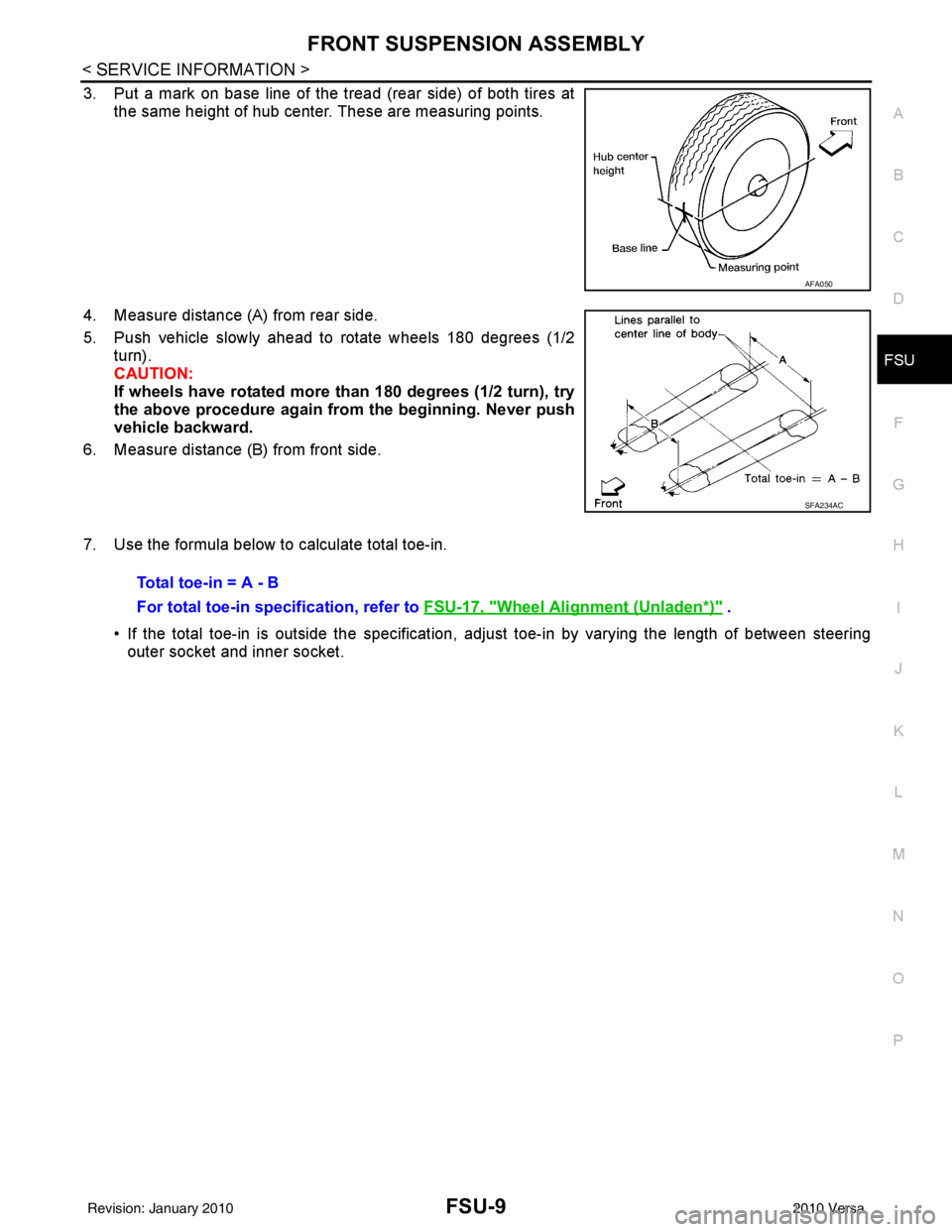
3. Put a mark on base line of the tread (rear side) of both tires at the same height of hub center. These are measuring points.
4. Measure distance (A) from rear side.
5. Push vehicle slowly ahead to rotate wheels 180 degrees (1/2 turn).
CAUTION:
If wheels have rotated more than 180 degrees (1/2 turn), try
the above procedure again from the beginning. Never push
vehicle backward.
6. Measure distance (B) from front side.
7. Use the formula below to calculate total toe-in.
• If the total toe-in is outside the specification, adjust toe-in by varying the length of between steeringouter socket and inner socket.
AFA050
SFA234AC
Total toe-in = A - B
For total toe-in specification, refer to FSU-17, "
Wheel Alignment (Unladen*)" .
Revision: January 20102010 Versa
Page 2657 of 3745
FSU-10
< SERVICE INFORMATION >
FRONT SUSPENSION ASSEMBLY
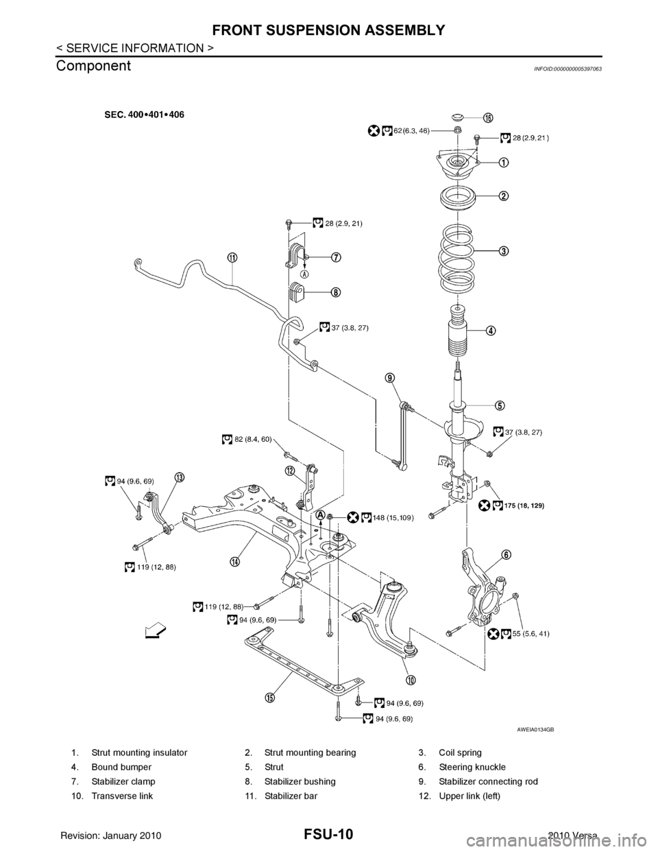
Component
INFOID:0000000005397063
1. Strut mounting insulator 2. Strut mounting bearing 3. Coil spring
4. Bound bumper 5. Strut 6. Steering knuckle
7. Stabilizer clamp 8. Stabilizer bushing9. Stabilizer connecting rod
10. Transverse link 11. Stabilizer bar12. Upper link (left)
AWEIA0134GB
Revision: January 20102010 Versa
Page 2658 of 3745
FRONT SUSPENSION ASSEMBLYFSU-11
< SERVICE INFORMATION >
C
DF
G H
I
J
K L
M A
B
FSU
N
O P
Removal and InstallationINFOID:0000000005397064
REMOVAL
1. Separate intermediate shaft from steering gear pinion shaft. Refer to PS-9, "Removal and Installation".
2. Remove front tires from vehicle using a power tool.
3. Remove wheel sensor from steering knuckle. Refer to BRC-34
.
CAUTION:
Do not pull on wheel sensor harness.
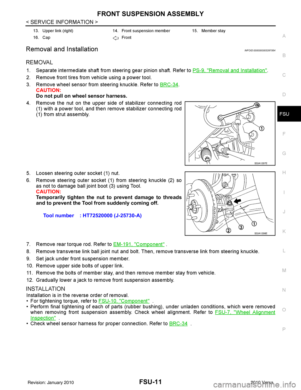
4. Remove the nut on the upper side of stabilizer connecting rod (1) with a power tool, and then remove stabilizer connecting rod
(1) from strut assembly.
5. Loosen steering outer socket (1) nut.
6. Remove steering outer socket (1) from steering knuckle (2) so as not to damage ball joint boot (3) using Tool.
CAUTION:
Temporarily tighten the nut to prevent damage to threads
and to prevent the Tool fr om suddenly coming off.
7. Remove rear torque rod. Refer to EM-191, "
Component" .
8. Remove transverse link ball joint nut and bolt. Then, remove transverse link from steering knuckle.
9. Set jack under front suspension member.
10. Remove upper side bolts of upper link.
11. Remove the bolts of member stay, and then remove member stay from vehicle.
12. Gradually lower a jack to remove front suspension assembly.
INSTALLATION
Installation is in the reverse order of removal.
• For tightening torque, refer to FSU-10, "
Component" .
• Perform final tightening of each of parts (rubber bushing), under unladen conditions, which were removed when removing front suspension assembly. Check wheel alignment. Refer to FSU-7, "
Wheel Alignment
Inspection" .
• Check wheel sensor harness for proper connection. Refer to BRC-34
.
13. Upper link (right)14. Front suspension member15. Member stay
16. Cap Front
SGIA1297E
Tool number : HT72520000 (J-25730-A)
SGIA1298E
Revision: January 20102010 Versa
Page 2659 of 3745
FSU-12
< SERVICE INFORMATION >
COIL SPRING AND STRUT
COIL SPRING AND STRUT
Removal and InstallationINFOID:0000000005397065
REMOVAL
1. Remove cowl top panel. Refer to EI-22, "Removal and Installation" .
2. Remove front tires using power tool.
3. Remove harness of wheel sensor from strut assembly. Refer to BRC-34, "
Removal and Installation" .
CAUTION:
Do not pull on wheel sensor harness.
4. Remove brake hose lock plate. Refer to BR-12, "
Rear Brake Tube and Hose" .
5. Remove the nut on the upper side of stabilizer connecting rod using power tool, and then remove stabi- lizer connecting rod from strut assembly.
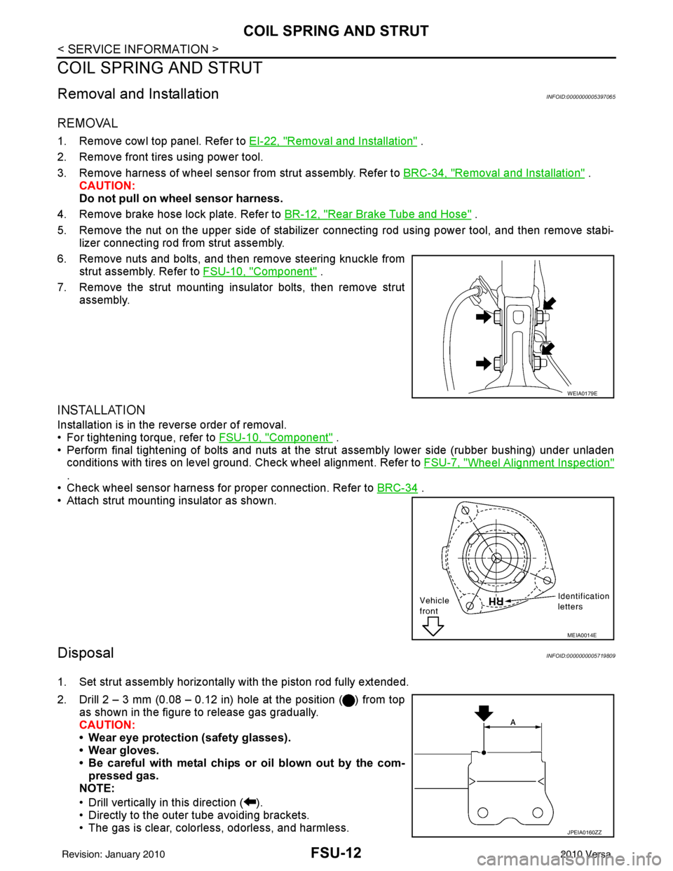
6. Remove nuts and bolts, and then remove steering knuckle from strut assembly. Refer to FSU-10, "
Component" .
7. Remove the strut mounting insulator bolts, then remove strut assembly.
INSTALLATION
Installation is in the reverse order of removal.
• For tightening torque, refer to FSU-10, "
Component" .
• Perform final tightening of bolts and nuts at the strut assembly lower side (rubber bushing) under unladen
conditions with tires on level ground. Check wheel alignment. Refer to FSU-7, "
Wheel Alignment Inspection"
.
• Check wheel sensor harness for proper connection. Refer to BRC-34
.
• Attach strut mounting insulator as shown.
DisposalINFOID:0000000005719809
1. Set strut assembly horizontally with the piston rod fully extended.
2. Drill 2 – 3 mm (0.08 – 0.12 in) hole at the position ( ) from top as shown in the figure to release gas gradually.
CAUTION:
• Wear eye protection (safety glasses).
• Wear gloves.
• Be careful with metal chips or oil blown out by the com-pressed gas.
NOTE:
• Drill vertically in this direction ( ).
• Directly to the outer tube avoiding brackets.
• The gas is clear, colorless, odorless, and harmless.
WEIA0179E
MEIA0014E
JPEIA0160ZZ
Revision: January 20102010 Versa
Page 2662 of 3745
TRANSVERSE LINKFSU-15
< SERVICE INFORMATION >
C
DF
G H
I
J
K L
M A
B
FSU
N
O P
TRANSVERSE LINK
Removal and InstallationINFOID:0000000005397067
REMOVAL
1. Remove front tires using power tool.
2. Remove transverse link ball joint nut and bolt. Then, remove transverse link from steering knuckle.
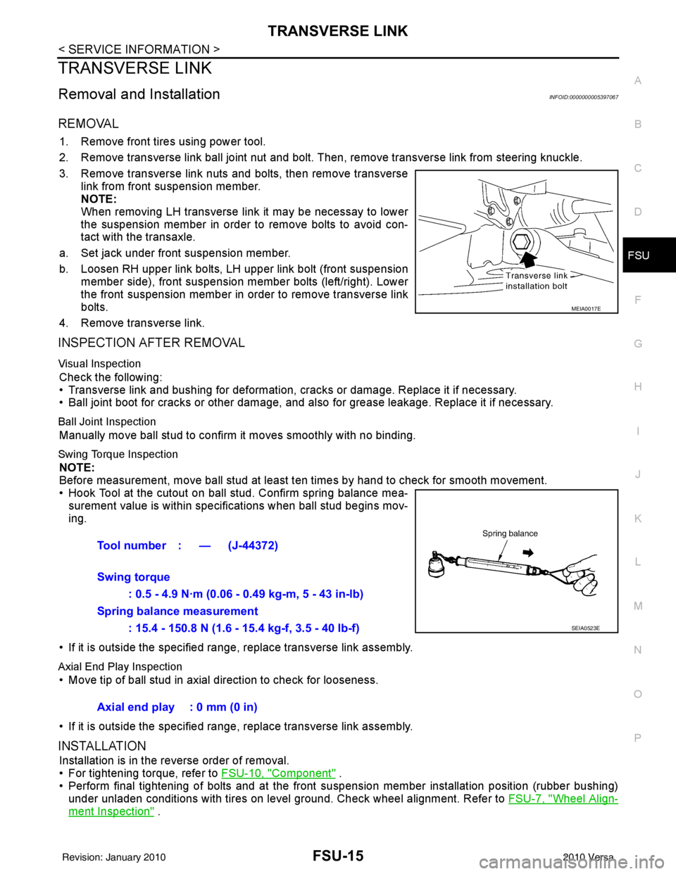
3. Remove transverse link nuts and bolts, then remove transverse link from front suspension member.
NOTE:
When removing LH transverse link it may be necessay to lower
the suspension member in order to remove bolts to avoid con-
tact with the transaxle.
a. Set jack under front suspension member.
b. Loosen RH upper link bolts, LH upper link bolt (front suspension member side), front suspension member bolts (left/right). Lower
the front suspension member in order to remove transverse link
bolts.
4. Remove transverse link.
INSPECTION AFTER REMOVAL
Visual Inspection
Check the following:
• Transverse link and bushing for deformation, cracks or damage. Replace it if necessary.
• Ball joint boot for cracks or other damage, and also for grease leakage. Replace it if necessary.
Ball Joint Inspection
Manually move ball stud to confirm it moves smoothly with no binding.
Swing Torque Inspection
NOTE:
Before measurement, move ball stud at least ten times by hand to check for smooth movement.
• Hook Tool at the cutout on ball stud. Confirm spring balance mea- surement value is within specifications when ball stud begins mov-
ing.
• If it is outside the specified range, replace transverse link assembly.
Axial End Play Inspection
• Move tip of ball stud in axial direction to check for looseness.
• If it is outside the specified range, replace transverse link assembly.
INSTALLATION
Installation is in the reverse order of removal.
• For tightening torque, refer to FSU-10, "
Component" .
• Perform final tightening of bolts and at the front suspension member installation position (rubber bushing)
under unladen conditions with tires on level ground. Check wheel alignment. Refer to FSU-7, "
Wheel Align-
ment Inspection" .
MEIA0017E
Tool number : — (J-44372)
Swing torque
: 0.5 - 4.9 N·m (0.06 - 0.49 kg-m, 5 - 43 in-lb)
Spring balance measurement : 15.4 - 150.8 N (1.6 - 15.4 kg-f, 3.5 - 40 lb-f)
SEIA0523E
Axial end play : 0 mm (0 in)
Revision: January 20102010 Versa
Page 2663 of 3745
FSU-16
< SERVICE INFORMATION >
STABILIZER BAR
STABILIZER BAR
Removal and InstallationINFOID:0000000005397068
REMOVAL
1. Separate intermediate shaft from steering gear pinion shaft. Refer to PS-9, "Removal and Installation" .
2. Remove front tires using power tool.
3. Remove the nut on the lower side of stabilizer connecting rod using power tool, and then remove stabilizer connecting rod from stabilizer bar.
4. If necessary remove stabilize connecting rod upper nut using power tool. Separate stabilizer connecting rod and strut.
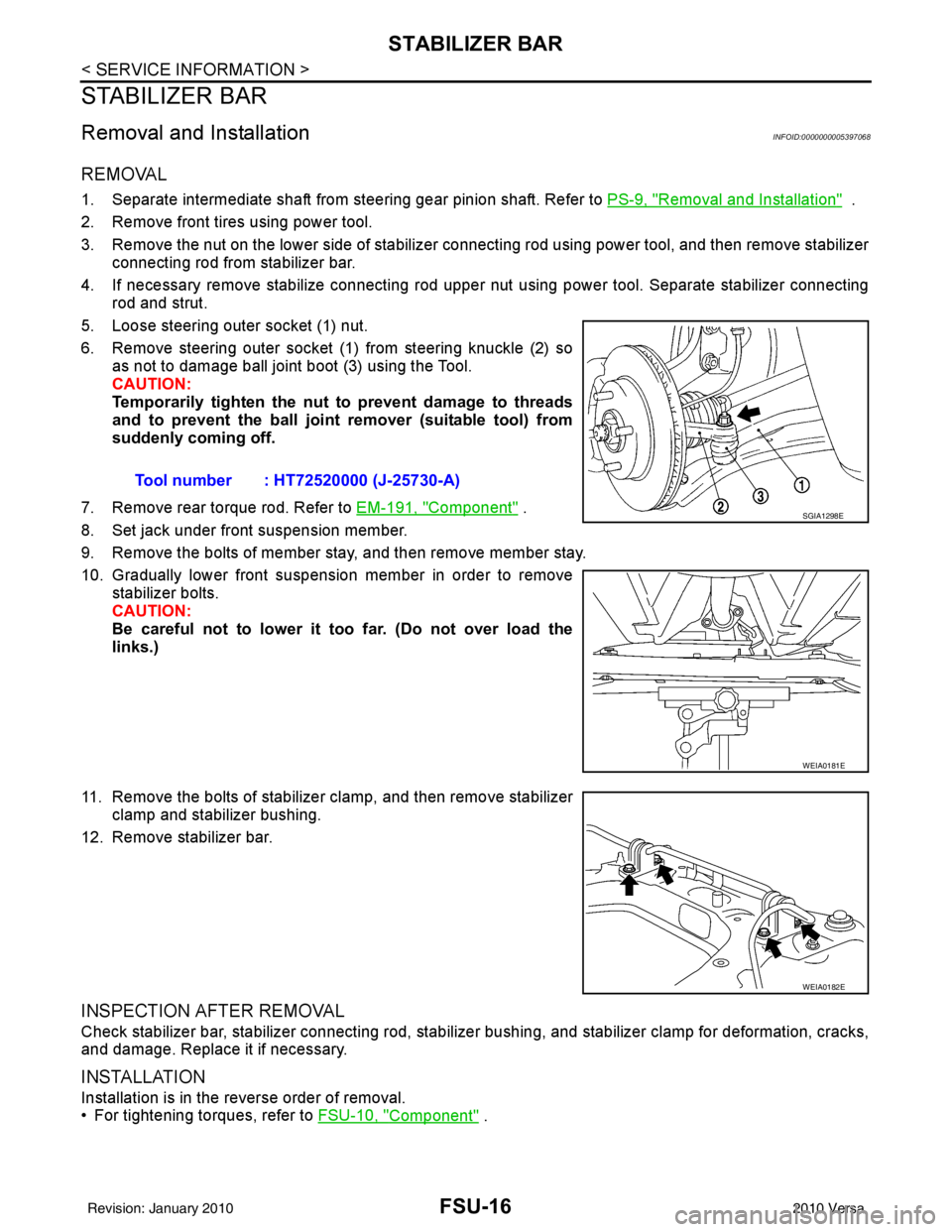
5. Loose steering outer socket (1) nut.
6. Remove steering outer socket (1) from steering knuckle (2) so as not to damage ball joint boot (3) using the Tool.
CAUTION:
Temporarily tighten the nut to prevent damage to threads
and to prevent the ball joint remover (suitable tool) from
suddenly coming off.
7. Remove rear torque rod. Refer to EM-191, "
Component" .
8. Set jack under front suspension member.
9. Remove the bolts of member stay, and then remove member stay.
10. Gradually lower front suspension member in order to remove stabilizer bolts.
CAUTION:
Be careful not to lower it too far. (Do not over load the
links.)
11. Remove the bolts of stabilizer clamp, and then remove stabilizer clamp and stabilizer bushing.
12. Remove stabilizer bar.
INSPECTION AFTER REMOVAL
Check stabilizer bar, stabilizer connecting rod, stabilizer bushing, and stabilizer clamp for deformation, cracks,
and damage. Replace it if necessary.
INSTALLATION
Installation is in the reverse order of removal.
• For tightening torques, refer to FSU-10, "
Component" .
Tool number : HT72520000 (J-25730-A)
SGIA1298E
WEIA0181E
WEIA0182E
Revision: January 20102010 Versa
Page 2667 of 3745

GI-1
GENERAL INFORMATION
C
DE
F
G H
I
J
K L
M B
GI
SECTION GI
N
O P
CONTENTS
GENERAL INFORMATION
SERVICE INFORMATION .. ..........................2
PRECAUTIONS .............................................. .....2
Description .......................................................... ......2
Precaution for Supplemental Restraint System
(SRS) "AIR BAG" and "SEAT BELT PRE-TEN-
SIONER" ...................................................................
2
Precaution Necessary for Steering Wheel Rota-
tion After Battery Disconnect ............................... ......
2
General Precaution ...................................................3
Precaution for Three Way Catalyst ...........................4
Precaution for Fuel (Unleaded Regular Gasoline
Recommended) .........................................................
4
Precaution for Multiport Fuel Injection System or
Engine Control System .............................................
5
Precaution for Hoses .................................................5
Precaution for Engine Oils ........................................6
Precaution for Air Conditioning .................................6
HOW TO USE THIS MANUAL ............................7
Description .......................................................... ......7
Terms ........................................................................7
Units ..........................................................................7
Contents ....................................................................7
Relation between Illustrations and Descriptions .......8
Component ................................................................8
How to Follow Trouble Diagnosis ..............................9
How to Read Wiring Diagram ..................................13
Abbreviations ...................................................... ....20
SERVICE INFORMATION FOR ELECTRICAL
INCIDENT ...........................................................
22
How to Check Terminal ...........................................22
How to Perform Efficient Diagnosis for an Electri-
cal Incident .......................................................... ....
25
Control Units and Electrical Parts ............................32
CONSULT-III CHECKING SYSTEM .................35
Description ...............................................................35
Function and System Application ............................35
CONSULT-III Data Link Connector (DLC) Circuit ....36
LIFTING POINT .................................................38
Special Service Tool ................................................38
Garage Jack and Safety Stand and 2-Pole Lift .......38
Board-On Lift ...........................................................39
TOW TRUCK TOWING .....................................40
Tow Truck Towing ...................................................40
Vehicle Recovery (Freeing a Stuck Vehicle) ...........40
TIGHTENING TORQUE OF STANDARD
BOLTS ...............................................................
41
Tightening Torque Table .........................................41
RECOMMENDED CHEMICAL PRODUCTS
AND SEALANTS ...............................................
42
Recommended Chemical Product and Sealant .......42
IDENTIFICATION INFORMATION ....................43
Model Variation ........................................................43
Dimensions ..............................................................46
Wheels & Tires ........................................................46
TERMINOLOGY ................................................48
SAE J1930 Terminology List ...................................48
Revision: January 20102010 Versa
Page 2668 of 3745
GI-2
< SERVICE INFORMATION >
PRECAUTIONS
SERVICE INFORMATION
PRECAUTIONS
DescriptionINFOID:0000000005399832
Observe the following precautions to ensure safe and proper servicing. These precautions are not
described in each individual section.
Precaution for Supplemental Restraint Syst em (SRS) "AIR BAG" and "SEAT BELT
PRE-TENSIONER"
INFOID:0000000005399833
The Supplemental Restraint System such as “A IR BAG” and “SEAT BELT PRE-TENSIONER”, used along
with a front seat belt, helps to reduce the risk or severity of injury to the driver and front passenger for certain
types of collision. This system includes seat belt switch inputs and dual stage front air bag modules. The SRS
system uses the seat belt switches to determine the front air bag deployment, and may only deploy one front
air bag, depending on the severity of a collision and w hether the front occupants are belted or unbelted.
Information necessary to service the system safely is included in the SRS and SB section of this Service Man-
ual.
WARNING:
• To avoid rendering the SRS inopera tive, which could increase the risk of personal injury or death in
the event of a collision which would result in air bag inflation, all maintenance must be performed by
an authorized NISSAN/INFINITI dealer.
• Improper maintenance, including incorrect removal and installation of the SRS can lead to personal
injury caused by unintent ional activation of the system. For re moval of Spiral Cable and Air Bag
Module, see the SRS section.
• Do not use electrical test equipmen t on any circuit related to the SRS unless instructed to in this
Service Manual. SRS wiring harn esses can be identified by yellow and/or orange harnesses or har-
ness connectors.
PRECAUTIONS WHEN USING POWER TOOLS (AIR OR ELECTRIC) AND HAMMERS
WARNING:
• When working near the Airbag Diagnosis Sensor Unit or other Airbag System sensors with the Igni-
tion ON or engine running, DO NOT use air or electri c power tools or strike near the sensor(s) with a
hammer. Heavy vibration could activate the sensor( s) and deploy the air bag(s), possibly causing
serious injury.
• When using air or electric power tools or hammers , always switch the Ignition OFF, disconnect the
battery, and wait at least 3 minu tes before performing any service.
Precaution Necessary for Steering W heel Rotation After Battery Disconnect
INFOID:0000000005399834
NOTE:
• This Procedure is applied only to models with Intelligent Key system and NATS (NISSAN ANTI-THEFT SYS-
TEM).
• Remove and install all control units after disconnecting both battery cables with the ignition knob in the
″LOCK ″ position.
• Always use CONSULT-III to perform self-diagnosis as a part of each function inspection after finishing work.
If DTC is detected, perform trouble diagnosis according to self-diagnostic results.
For models equipped with the Intelligent Key system and NATS, an electrically controlled steering lock mech-
anism is adopted on the key cylinder.
For this reason, if the battery is disconnected or if the battery is discharged, the steering wheel will lock and
steering wheel rotation will become impossible.
If steering wheel rotation is required when battery pow er is interrupted, follow the procedure below before
starting the repair operation.
OPERATION PROCEDURE
1. Connect both battery cables. NOTE:
Supply power using jumper cables if battery is discharged.
Revision: January 20102010 Versa