2010 NISSAN LATIO tow
[x] Cancel search: towPage 677 of 3745
BL-168
< SERVICE INFORMATION >
FRONT DOOR LOCK
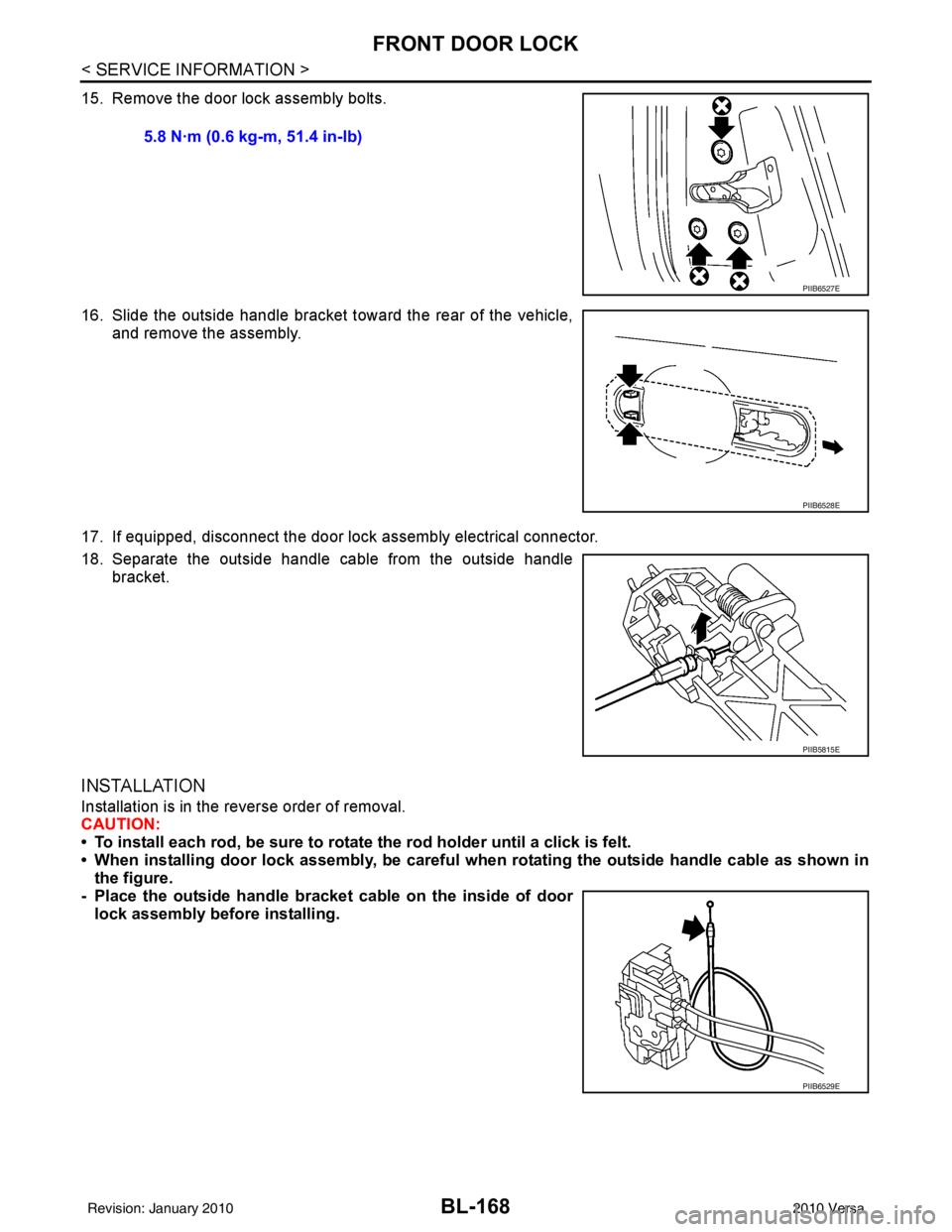
15. Remove the door lock assembly bolts.
16. Slide the outside handle bracket toward the rear of the vehicle,and remove the assembly.
17. If equipped, disconnect the door lock assembly electrical connector.
18. Separate the outside handle cable from the outside handle bracket.
INSTALLATION
Installation is in the reverse order of removal.
CAUTION:
• To install each rod, be sure to rotate the rod holder until a click is felt.
• When installing door lock assembly, be careful wh en rotating the outside handle cable as shown in
the figure.
- Place the outside handle bracket cable on the inside of door
lock assembly before installing. 5.8 N·m (0.6 kg-m, 51.4 in-lb)
PIIB6527E
PIIB6528E
PIIB5815E
PIIB6529E
Revision: January 20102010 Versa
Page 678 of 3745
REAR DOOR LOCKBL-169
< SERVICE INFORMATION >
C
DE
F
G H
J
K L
M A
B
BL
N
O P
REAR DOOR LOCK
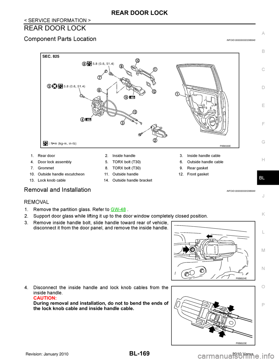
Component Parts LocationINFOID:0000000005396648
Removal and InstallationINFOID:0000000005396649
REMOVAL
1. Remove the partition glass. Refer to GW-48 .
2. Support door glass while lifting it up to the door window completely closed position.
3. Remove inside handle bolt, slide handle toward rear of vehicle, disconnect it from the door panel, and remove the inside handle.
4. Disconnect the inside handle and lock knob cables from the inside handle.
CAUTION:
During removal and installation, do not to bend the ends of
the lock knob cable and inside handle cable.
1. Rear door 2. Inside handle 3. Inside handle cable
4. Door lock assembly 5. TORX bolt (T30) 6. Outside handle cable
7. Grommet 8. TORX bolt (T30) 9. Rear gasket
10. Outside handle escutcheon 11. Outside handle12. Front gasket
13. Lock knob cable 14. Outside handle bracket
PIIB6530E
PIIB6524E
PIIB6525E
Revision: January 20102010 Versa
Page 679 of 3745
BL-170
< SERVICE INFORMATION >
REAR DOOR LOCK
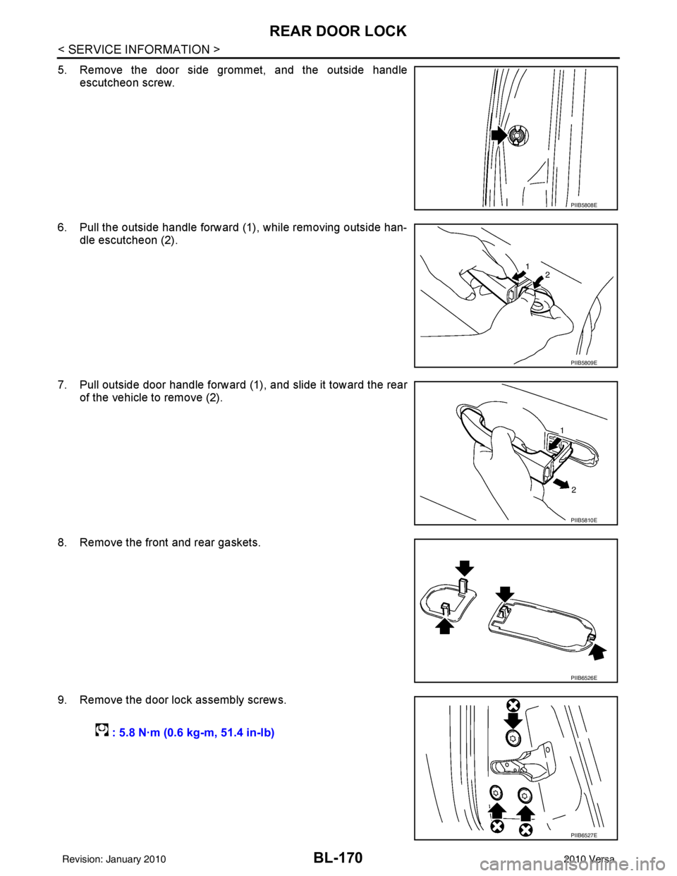
5. Remove the door side grommet, and the outside handleescutcheon screw.
6. Pull the outside handle forward (1), while removing outside han- dle escutcheon (2).
7. Pull outside door handle forward (1), and slide it toward the rear of the vehicle to remove (2).
8. Remove the front and rear gaskets.
9. Remove the door lock assembly screws.
PIIB5808E
PIIB5809E
PIIB5810E
PIIB6526E
: 5.8 N·m (0.6 kg-m, 51.4 in-lb)
PIIB6527E
Revision: January 20102010 Versa
Page 680 of 3745
REAR DOOR LOCKBL-171
< SERVICE INFORMATION >
C
DE
F
G H
J
K L
M A
B
BL
N
O P
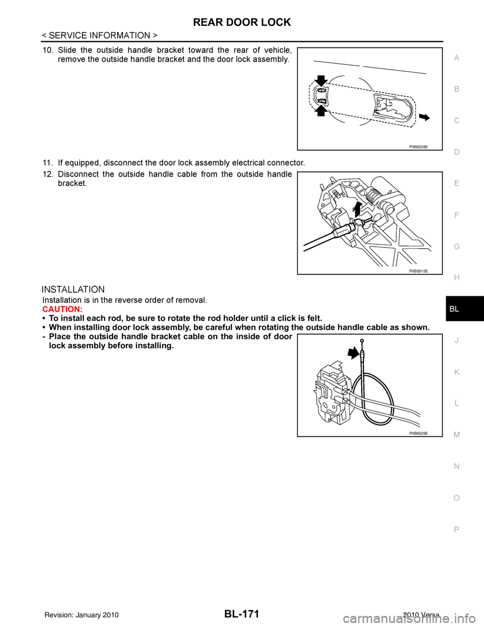
10. Slide the outside handle bracket toward the rear of vehicle, remove the outside handle bracket and the door lock assembly.
11. If equipped, disconnect the door lock assembly electrical connector.
12. Disconnect the outside handle cable from the outside handle bracket.
INSTALLATION
Installation is in the reverse order of removal.
CAUTION:
• To install each rod, be sure to rotate the rod holder until a click is felt.
• When installing door lock assembly, be careful when rotating the outside handle cable as shown.
- Place the outside handle bracket cable on the inside of door
lock assembly before installing.
PIIB6528E
PIIB5815E
PIIB6529E
Revision: January 20102010 Versa
Page 779 of 3745

BL-270
< SERVICE INFORMATION >
BODY REPAIR
4. Front pillar inner reinforcement (RH&LH)
5. Lower dash reinforcement
6. 4th crossmember (RH&LH)
7. Front side member rear extension (RH&LH)
8. 3rd crossmember (RH&LH)
9. Front seat outer rear bracket (RH&LH)
10. Front seat inner rear bracket (RH&LH)
11. 2nd crossmember (RH&LH)
12. Front seat outer front bracket (RH&LH)
13. Front seat inner front bracket (RH&LH)
14. Fender bracket (RH&LH)
15. Strut housing assembly RH
16. Cowl top side upper (RH&LH)
17. Front strut housing (RH&LH)
18. Upper torque rod reinforcement
19. Closing plate assembly RH
20. Engine mount reinforcement
21. Strut tower front reinforcement RH
22. Front hoodledge lower RH
23. Frame bracket outer (RH&LH)
24. Front bumper support bracket (RH&LH)
25. Closing plate (RH&LH)
26. Front suspension rear bracket (RH&LH)
27. Front side member outrigger (RH&LH)
28. Front side member assembly (RH&LH)
29. Front side member (RH&LH)
30. Frame bracket (RH&LH)
31. Closing plate assembly LH
32. Hoodledge connector (RH&LH)
33. Radiator core side support (RH&LH)
34. Radiator core support upper (RH&LH)
35. Hoodledge upper (RH&LH)
36. Hoodledge reinforcement assembly (RH&LH)
37. Dash side (RH&LH)
38. Dash side assembly (RH& LH)
39. Front floor reinforcement (RH&LH)
40. Front floor front (RH&LH)
41. Front floor center
42. Rear seat crossmember
43. Rear center crossmember
44. Rear seat upper crossmember
45. Rear side member (RH&LH)
46. Sill inner extension (RH&LH)
47. Rear side member extension (RH&LH)
48. Rear side member assembly (RH & LH)
49. Rear floor front
50. Rear floor front assembly
51. Rear floor side (RH&LH)
52. Rear floor rear
Revision: January 20102010 Versa
Page 866 of 3745
BR-18
< SERVICE INFORMATION >
BRAKE MASTER CYLINDER
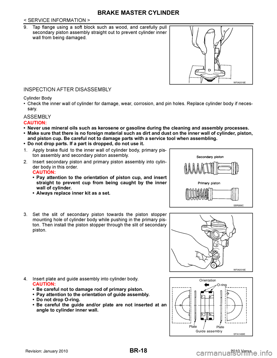
9. Tap flange using a soft block such as wood, and carefully pullsecondary piston assembly straight out to prevent cylinder inner
wall from being damaged.
INSPECTION AFTER DISASSEMBLY
Cylinder Body
• Check the inner wall of cylinder for damage, wear, corrosion, and pin holes. Replace cylinder body if neces-sary.
ASSEMBLY
CAUTION:
• Never use mineral oils such as kerosene or g asoline during the cleaning and assembly processes.
• Make sure that there is no foreign material such as dirt and dust on the inner wall of cylinder, piston,
and piston cup. Be careful not to damage parts with a service tool when assembling.
• Do not drop parts. If a part is dropped, do not use it.
1. Apply brake fluid to the inner wall of cylinder body, primary pis- ton assembly and secondary piston assembly.
2. Insert secondary piston and primary piston assembly into cylin- der body in this order.
CAUTION:
• Pay attention to the orientation of piston cup, and insert
straight to prevent cup from being caught by the inner
wall of cylinder.
• Always replace inner kit as a set.
3. Set the slit of secondary piston towards the piston stopper mounting hole of cylinder body while pushing in the primary pis-
ton. Then install the piston stopper through the slit of secondary
piston.
4. Insert plate and guide assembly into cylinder body. CAUTION:
• Be careful not to damage rod of primary piston.
• Pay attention to the orientation of guide assembly.
• Do not drop O-ring.
• Be careful the guide and/or plate are not inserted at an
angle to cylinder inner wall.
WFIA0518E
SBR089C
WFIA0516E
SFIA1469E
Revision: January 20102010 Versa
Page 930 of 3745
![NISSAN LATIO 2010 Service Repair Manual BRC-40
< SERVICE INFORMATION >[VDC/TCS/ABS]
PRECAUTIONS
5. When the repair work is completed, return the ignition switch to the
″LOCK ″ position before connecting
the battery cables. (At this tim NISSAN LATIO 2010 Service Repair Manual BRC-40
< SERVICE INFORMATION >[VDC/TCS/ABS]
PRECAUTIONS
5. When the repair work is completed, return the ignition switch to the
″LOCK ″ position before connecting
the battery cables. (At this tim](/manual-img/5/57358/w960_57358-929.png)
BRC-40
< SERVICE INFORMATION >[VDC/TCS/ABS]
PRECAUTIONS
5. When the repair work is completed, return the ignition switch to the
″LOCK ″ position before connecting
the battery cables. (At this time, the steering lock mechanism will engage.)
6. Perform a self-diagnosis check of a ll control units using CONSULT-III.
Precaution for Brake SystemINFOID:0000000005612137
CAUTION:
• Refer to MA-14, "
Fluids and Lubricants" for recommended brake fluid.
• Never reuse drained brake fluid.
• Be careful not to splash brake fluid on painted areas; it may cause paint damage. If brake fluid is
splashed on painted areas, wash it away with water immediately.
• To clean or wash all parts of master cylin der and disc brake caliper, use clean brake fluid.
• Never use mineral oils such as gasoline or kerosene. They will ruin rubber parts of the hydraulic sys-
tem.
• Use flare nut wrench when removing and installing brake
tube.
• If a brake fluid leak is found, the part must be disassembled without fail. Then it has to be replaced with a new one if a
defect exists.
• Turn the ignition switch OFF an d remove the connector of the
ABS actuator and electric unit (c ontrol unit) or the battery ter-
minal before performing the work.
• Always torque brake lines when installing.
• Burnish the brake contact surf aces after refinishing or replac-
ing rotors, after replacing pads, or if a soft pedal occurs at
very low mileage.
Refer to BR-34, "
Brake Burnishing Procedure".
WARNING:
• Clean brake pads and shoes with a waste cloth, then wipe with a dust collector.
Precaution for Brake ControlINFOID:0000000005612138
• During ABS operation, the brake pedal may vibrate lightly and a mechanical noise may be heard. This is
normal.
• Just after starting vehicle, the brake pedal may vibrate or a motor operating noise may be heard from engine compartment. This is a normal status of operation check.
• Stopping distance may be longer than that of vehicles without ABS when vehicle drives on rough, gravel, or
snow-covered (fresh, deep snow) roads.
• When an error is indicated by ABS or another warning la mp, collect all necessary information from customer
(what symptoms are present under what conditions) and check for simple causes before starting diagnosis.
Besides electrical system inspection, check booste r operation, brake fluid level, and fluid leaks.
• If incorrect tire sizes or types are installed on the v ehicle or brake pads are not Genuine NISSAN parts, stop-
ping distance or steering stability may deteriorate.
• If there is a radio, antenna or related wiring near control module, ABS function may have a malfunction or
error.
• If aftermarket parts (car stereo, CD player, etc.) have been installed, check for incidents such as harness
pinches, open circuits or improper wiring.
• If the following components are replaced with non-genuine components or modified, the VDC OFF indicator
lamp and SLIP indicator lamp may turn on or the VDC system may not operate properly. Components
related to suspension (shock absorbers, struts, spri ngs, bushings, etc.), tires, wheels (exclude specified
size), components related to brake system (pads, rotors , calipers, etc.), components related to engine (muf-
fler, ECM, etc.), components related to body reinforcement (roll bar, tower bar, etc.).
• Driving with broken or excessively worn suspension components, tires or brake system components may cause the VDC OFF indicator lamp and the SLIP indi cator lamp to turn on, and the VDC system may not
operate properly.
• When the TCS or VDC is activated by sudden accele ration or sudden turn, some noise may occur. The
noise is a result of the normal operation of the TCS and VDC.
• When driving on roads which have extreme slopes (such as mountainous roads) or high banks (such as
sharp curves on a freeway), the VDC may not operate nor mally, or the VDC warning lamp and the SLIP indi-
cator lamp may turn on. This is not a problem if normal operation can be resumed after restarting the engine.
SBR686C
Revision: January 20102010 Versa
Page 1047 of 3745
![NISSAN LATIO 2010 Service Repair Manual CVT-14
< SERVICE INFORMATION >[RE0F08B]
CVT FLUID
CVT FLUID
Checking CVT FluidINFOID:0000000005397767
FLUID LEVEL CHECK
Fluid level should be checked with the fluid warmed up to 50
° to 80° C (122° NISSAN LATIO 2010 Service Repair Manual CVT-14
< SERVICE INFORMATION >[RE0F08B]
CVT FLUID
CVT FLUID
Checking CVT FluidINFOID:0000000005397767
FLUID LEVEL CHECK
Fluid level should be checked with the fluid warmed up to 50
° to 80° C (122°](/manual-img/5/57358/w960_57358-1046.png)
CVT-14
< SERVICE INFORMATION >[RE0F08B]
CVT FLUID
CVT FLUID
Checking CVT FluidINFOID:0000000005397767
FLUID LEVEL CHECK
Fluid level should be checked with the fluid warmed up to 50
° to 80° C (122° to 176°F).
1. Check for fluid leakage.
2. With the engine warmed up, drive the vehicle to warm up the CVT fluid. When ambient temperature is 20 °C (68° F), it takes
about 10 minutes for the CVT fluid to warm up to 50 ° to 80° C
(122° to 176 °F).
3. Park the vehicle on a level surface and set the parking brake.
4. With engine at idle, while depressing brake pedal, move the selector lever throughout the entire shift range and return it to
the “P” position.
5. Press the tab on the CVT fluid level gauge to release the lock and pull out the CVT fluid level gauge from the CVT fluid charg-
ing pipe.
6. Wipe fluid off the CVT fluid level gauge. Then rotate the CVT fluid level gauge 180 ° and re-insert it into the CVT charging pipe
as far as it will go.
CAUTION:
Always use lint free paper towels to wipe fluid off the CVT
fluid level gauge.
7. Remove the CVT fluid level gauge and check that the fluid level is within the specified range as shown. If the fluid level is at or
below the low side of the range, add the necessary specified
NISSAN CVT fluid through the CVT charging pipe.
CAUTION:
• Only use specified NISSAN CVT fluid.
• Do not overfill the CVT.
8. Install the CVT fluid level gauge to the CVT fluid charging pipe until it locks. CAUTION:
When CVT fluid level gauge is in stalled into the CVT fluid charging pipe, make sure that the CVT
fluid level gauge is securely locked in place.
SMA146B
SCIA1933E
SCIA1931E
Fluid grade: Refer to MA-14, "Fluids and Lubri-
cants".
SCIA1932E
Revision: January 20102010 Versa