Page 1981 of 3745
EC-716
< SERVICE INFORMATION >[MR18DE]
DTC P0132 A/F SENSOR 1
DTC P0132 A/F SENSOR 1
Component DescriptionINFOID:0000000005532556
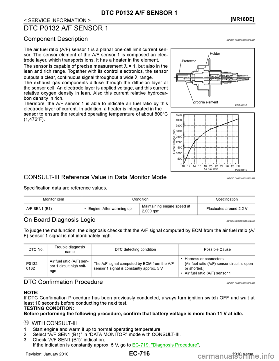
The air fuel ratio (A/F) sensor 1 is a planar one-cell limit current sen-
sor. The sensor element of the
A/F sensor 1 is composed an elec-
trode layer, which transports ions. It has a heater in the element.
The sensor is capable of precise measurement = 1, but also in the
lean and rich range. Together with its control electronics, the sensor
outputs a clear, continuous signal throughout a wide range.
The exhaust gas components diffuse through the diffusion layer at
the sensor cell. An electrode layer is applied voltage, and this current
relative oxygen density in lean. Also this current relative hydrocar-
bon density in rich.
Therefore, the A/F sensor 1 is able to indicate air fuel ratio by this
electrode layer of current. In addition, a heater is integrated in the
sensor to ensure the required operating temperature of about 800° C
(1,472° F).
CONSULT-III Reference Value in Data Monitor ModeINFOID:0000000005532557
Specification data are reference values.
On Board Diagn osis LogicINFOID:0000000005532558
To judge the malfunction, the diagnosis c hecks that the A/F signal computed by ECM from the air fuel ratio (A/
F) sensor 1 signal is not inordinately high.
DTC Confirmation ProcedureINFOID:0000000005532559
NOTE:
If DTC Confirmation Procedure has been previously conducted, always turn ignition switch OFF and wait at
least 10 seconds before conducting the next test.
TESTING CONDITION:
Before performing the following procedure, confirm that battery voltage is more than 11 V at idle.
WITH CONSULT-III
1. Start engine and warm it up to normal operating temperature.
2. Select “A/F SEN1 (B1)” in “DATA MONITOR” mode with CONSULT-III.
3. Check “A/F SEN1 (B1)” indication.
If the indication is constantly approx. 5 V, go to EC-719, "
Diagnosis Procedure".
PBIB3353E
PBIB3354E
Monitor item ConditionSpecification
A/F SEN1 (B1) • Engine: After warming upMaintaining engine speed at
2,000 rpm Fluctuates around 2.2 V
DTC No.Trouble diagnosis
name DTC detecting condition
Possible Cause
P0132
0132 Air fuel ratio (A/F) sen-
sor 1 circuit high volt-
age The A/F signal computed by ECM from the A/F
sensor 1 signal is constantly approx. 5 V. • Harness or connectors
[Air fuel ratio (A/F) sensor circuit is open
or shorted.]
• Air fuel ratio (A/F) sensor 1
Revision: January 20102010 Versa
Page 2015 of 3745
EC-750
< SERVICE INFORMATION >[MR18DE]
DTC P014C, P014D, P015A, P015B, A/F SENSOR 1
DTC P014C, P014D, P015A, P015B, A/F SENSOR 1
Component DescriptionINFOID:0000000005612766
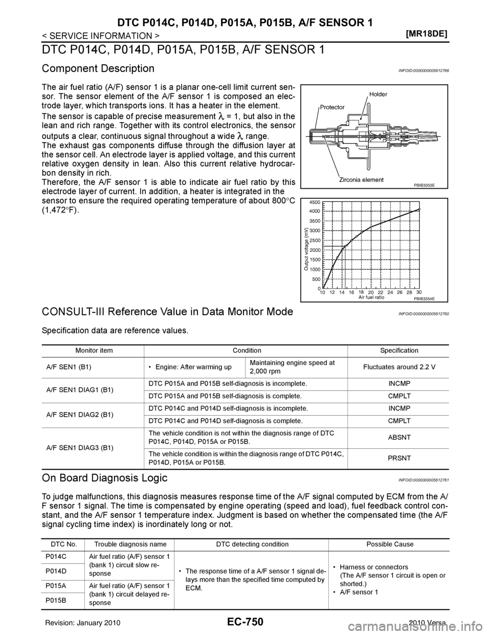
The air fuel ratio (A/F) sensor 1 is a planar one-cell limit current sen-
sor. The sensor element of the
A/F sensor 1 is composed an elec-
trode layer, which transports ions. It has a heater in the element.
The sensor is capable of precise measurement = 1, but also in the
lean and rich range. Together with its control electronics, the sensor
outputs a clear, continuous signal throughout a wide range.
The exhaust gas components diffuse through the diffusion layer at
the sensor cell. An electrode layer is applied voltage, and this current
relative oxygen density in lean. Also this current relative hydrocar-
bon density in rich.
Therefore, the A/F sensor 1 is able to indicate air fuel ratio by this
electrode layer of current. In addition, a heater is integrated in the
sensor to ensure the required operating temperature of about 800° C
(1,472° F).
CONSULT-III Reference Value in Data Monitor ModeINFOID:0000000005612760
Specification data are reference values.
On Board Diagn osis LogicINFOID:0000000005612761
To judge malfunctions, this diagnosis measures response time of the A/F signal computed by ECM from the A/
F sensor 1 signal. The time is compensated by engi ne operating (speed and load), fuel feedback control con-
stant, and the A/F sensor 1 temperature index. Judgment is based on whether the compensated time (the A/F
signal cycling time index) is inordinately long or not.
PBIB3353E
PBIB3354E
Monitor item ConditionSpecification
A/F SEN1 (B1) • Engine: After warming upMaintaining engine speed at
2,000 rpm Fluctuates around 2.2 V
A/F SEN1 DIAG1 (B1) DTC P015A and P015B self-diagnosis is incomplete.
INCMP
DTC P015A and P015B self-diagnosis is complete. CMPLT
A/F SEN1 DIAG2 (B1) DTC P014C and P014D self-diagnosis is incomplete.
INCMP
DTC P014C and P014D self-diagnosis is complete. CMPLT
A/F SEN1 DIAG3 (B1) The vehicle condition is not within the diagnosis range of DTC
P014C, P014D, P015A or P015B.
ABSNT
The vehicle condition is within the diagnosis range of DTC P014C,
P014D, P015A or P015B. PRSNT
DTC No. Trouble diagnosis name
DTC detecting conditionPossible Cause
P014C Air fuel ratio (A/F) sensor 1 (bank 1) circuit slow re-
sponse • The response time of a A/F sensor 1 signal de-
lays more than the specified time computed by
ECM. • Harness or connectors
(The A/F sensor 1 circuit is open or
shorted.)
• A/F sensor 1
P014D
P015A Air fuel ratio (A/F) sensor 1
(bank 1) circuit delayed re-
sponse
P015B
Revision: January 20102010 Versa
Page 2254 of 3745
DTC P2A00 A/F SENSOR 1EC-989
< SERVICE INFORMATION > [MR18DE]
C
D
E
F
G H
I
J
K L
M A
EC
NP
O
DTC P2A00 A/F SENSOR 1
Component DescriptionINFOID:0000000005532886
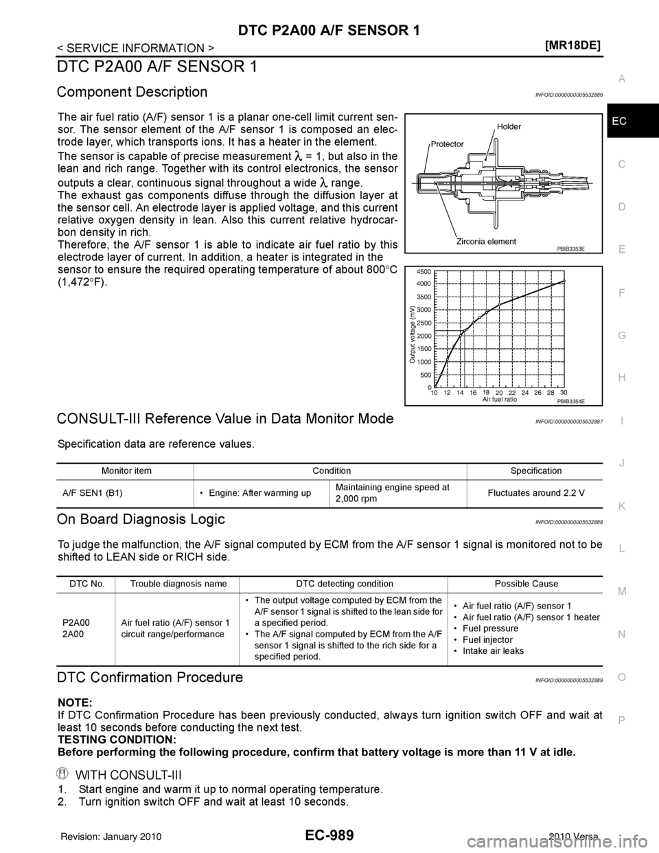
The air fuel ratio (A/F) sensor 1 is a planar one-cell limit current sen-
sor. The sensor element of the A/F sensor 1 is composed an elec-
trode layer, which transports ions. It has a heater in the element.
The sensor is capable of precise m
easurement = 1, but also in the
lean and rich range. Together with its control electronics, the sensor
outputs a clear, continuous signal throughout a wide range.
The exhaust gas components diffuse through the diffusion layer at
the sensor cell. An electrode layer is applied voltage, and this current
relative oxygen density in lean. Also this current relative hydrocar-
bon density in rich.
Therefore, the A/F sensor 1 is able to indicate air fuel ratio by this
electrode layer of current. In addition, a heater is integrated in the
sensor to ensure the required operating temperature of about 800 °C
(1,472 °F).
CONSULT-III Reference Val ue in Data Monitor ModeINFOID:0000000005532887
Specification data are reference values.
On Board Diagnosis LogicINFOID:0000000005532888
To judge the malfunction, the A/F signal computed by ECM from the A/F sensor 1 signal is monitored not to be
shifted to LEAN side or RICH side.
DTC Confirmation ProcedureINFOID:0000000005532889
NOTE:
If DTC Confirmation Procedure has been previously conducted, always turn ignition switch OFF and wait at
least 10 seconds before conducting the next test.
TESTING CONDITION:
Before performing the following procedure, confirm that battery voltage is more than 11 V at idle.
WITH CONSULT-III
1. Start engine and warm it up to normal operating temperature.
2. Turn ignition switch OFF and wait at least 10 seconds.
PBIB3353E
PBIB3354E
Monitor itemConditionSpecification
A/F SEN1 (B1) • Engine: After warming upMaintaining engine speed at
2,000 rpm Fluctuates around 2.2 V
DTC No. Trouble diagnosis name
DTC detecting conditionPossible Cause
P2A00
2A00 Air fuel ratio (A/F) sensor 1
circuit range/performance • The output voltage computed by ECM from the
A/F sensor 1 signal is shifted to the lean side for
a specified period.
• The A/F signal computed by ECM from the A/F
sensor 1 signal is shifted to the rich side for a
specified period. • Air fuel ratio (A/F) sensor 1
• Air fuel ratio (A/F) sensor 1 heater
• Fuel pressure
• Fuel injector
• Intake air leaks
Revision: January 20102010 Versa