2010 NISSAN LATIO warning
[x] Cancel search: warningPage 1260 of 3745
DI-50
< SERVICE INFORMATION >
WARNING CHIME
OK >> Check battery power supply circuit of combination meter. If OK, replace combination meter. Referto IP-12, "
Removal and Installation".
NG >> Replace BCM. Refer to BCS-19, "
Removal and Installation of BCM".
Front Door Switch LH Signal InspectionINFOID:0000000005395046
1.CHECK BCM INPUT SIGNAL
With CONSULT-III
1. Select “BCM”.
2. With “DATA MONITOR” of “BUZZER”, confirm “DOOR SW-DR” when the driver's door is operated.
Without CONSULT-III
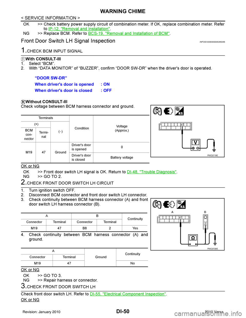
Check voltage between BCM harness connector and ground.
OK or NG
OK >> Front door switch LH signal is OK. Return to DI-48, "Trouble Diagnosis".
NG >> GO TO 2.
2.CHECK FRONT DOOR SWITCH LH CIRCUIT
1. Turn ignition switch OFF.
2. Disconnect BCM connector and front door switch LH connector.
3. Check continuity between BCM harness connector (A) and front door switch LH harness connector (B).
4. Check continuity between BCM harness connector (A) and ground.
OK or NG
OK >> GO TO 3.
NG >> Repair harness or connector.
3.CHECK FRONT DOOR SWITCH LH
Check front door switch LH. Refer to DI-55, "
Electrical Component Inspection".
OK or NG
“DOOR SW-DR”
When driver's door is opened : ON
When driver's door is closed : OFF
Te r m i n a l s
Condition Vol tag e
(Approx.)
(+)
(−)
BCM
con-
nector Te r m i -
nal
M19 47 Ground Driver's door
is opened
0
Driver's door
is closed Battery voltage
PKIC0719E
AB
Continuity
Connector Terminal Connector Terminal
M19 47B8 2Yes
A GroundContinuity
Connector Terminal
M19 47 No
PKIC0720E
Revision: January 20102010 Versa
Page 1261 of 3745
WARNING CHIMEDI-51
< SERVICE INFORMATION >
C
DE
F
G H
I
J
L
M A
B
DI
N
O P
OK >> Replace BCM. Refer to BCS-19, "Removal and Installation of BCM".
NG >> Replace front door switch LH.
Key Switch Signal Inspection (Without Intelligent Key)INFOID:0000000005395047
1.CHECK FUSE
Check if the key switch and key lock solenoid 10A fuse [No. 14, located in the fuse block (J/B)] is blown.
OK or NG
OK >> GO TO 2.
NG >> Be sure to repair the cause of malfunction before installing new fuse. Refer to PG-4
.
2.CHECK BCM INPUT SIGNAL
With CONSULT-III
1. Select “BCM”.
2. With “DATA MONITOR” of “BUZZER”, confirm “KEY ON SW” when the key is operated.
Without CONSULT-III
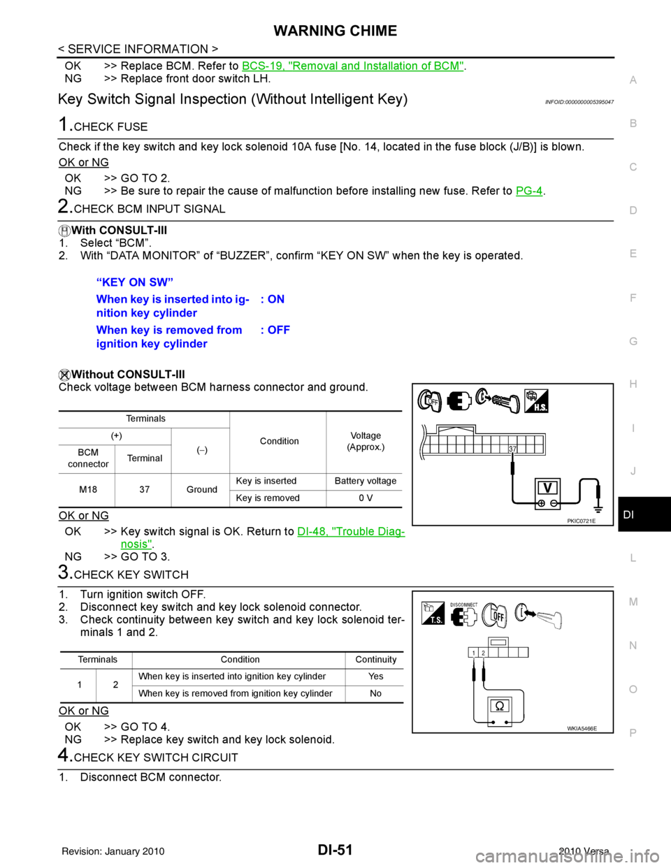
Check voltage between BCM harness connector and ground.
OK or NG
OK >> Key switch signal is OK. Return to DI-48, "Trouble Diag-
nosis".
NG >> GO TO 3.
3.CHECK KEY SWITCH
1. Turn ignition switch OFF.
2. Disconnect key switch and key lock solenoid connector.
3. Check continuity between key switch and key lock solenoid ter- minals 1 and 2.
OK or NG
OK >> GO TO 4.
NG >> Replace key switch and key lock solenoid.
4.CHECK KEY SWITCH CIRCUIT
1. Disconnect BCM connector. “KEY ON SW”
When key is inserted into ig-
nition key cylinder
: ON
When key is removed from
ignition key cylinder : OFF
Te r m i n a l s
ConditionVoltag e
(Approx.)
(+)
(−)
BCM
connector Te r m i n a l
M18 37 Ground Key is inserted Battery voltage
Key is removed
0 V
PKIC0721E
Terminals ConditionContinuity
12 When key is inserted into ignition key cylinder Yes
When key is removed from ignition key cylinder No
WKIA5466E
Revision: January 20102010 Versa
Page 1262 of 3745
DI-52
< SERVICE INFORMATION >
WARNING CHIME
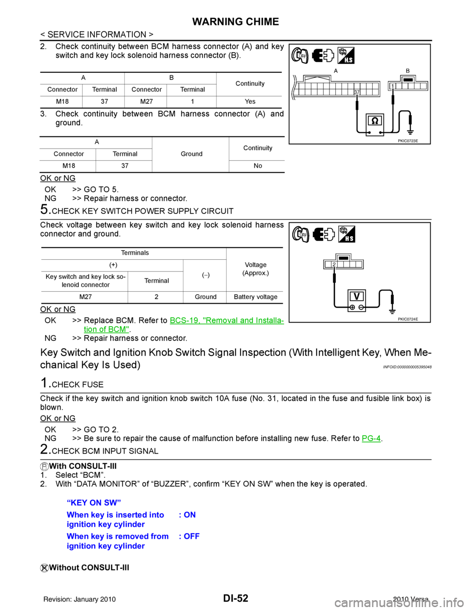
2. Check continuity between BCM harness connector (A) and keyswitch and key lock solenoid harness connector (B).
3. Check continuity between BCM harness connector (A) and ground.
OK or NG
OK >> GO TO 5.
NG >> Repair harness or connector.
5.CHECK KEY SWITCH PO WER SUPPLY CIRCUIT
Check voltage between key switch and key lock solenoid harness
connector and ground.
OK or NG
OK >> Replace BCM. Refer to BCS-19, "Removal and Installa-
tion of BCM".
NG >> Repair harness or connector.
Key Switch and Ignition Knob Switch Signal Inspection (With Intelligent Key, When Me-
chanical Key Is Used)
INFOID:0000000005395048
1.CHECK FUSE
Check if the key switch and ignition knob switch 10A fuse (No. 31, located in the fuse and fusible link box) is
blown.
OK or NG
OK >> GO TO 2.
NG >> Be sure to repair the cause of malfunction before installing new fuse. Refer to PG-4
.
2.CHECK BCM INPUT SIGNAL
With CONSULT-III
1. Select “BCM”.
2. With “DATA MONITOR” of “BUZZER”, c onfirm “KEY ON SW” when the key is operated.
Without CONSULT-III
AB Continuity
Connector Terminal Connector Terminal
M18 37 M27 1Yes
A GroundContinuity
Connector Terminal
M18 37 No
PKIC0723E
Te r m i n a l s
Voltage
(Approx.)
(+)
(−)
Key switch and key lock so-
lenoid connector Te r m i n a l
M27 2Ground Battery voltage
PKIC0724E
“KEY ON SW”
When key is inserted into
ignition key cylinder : ON
When key is removed from
ignition key cylinder : OFF
Revision: January 20102010 Versa
Page 1263 of 3745
WARNING CHIMEDI-53
< SERVICE INFORMATION >
C
DE
F
G H
I
J
L
M A
B
DI
N
O P
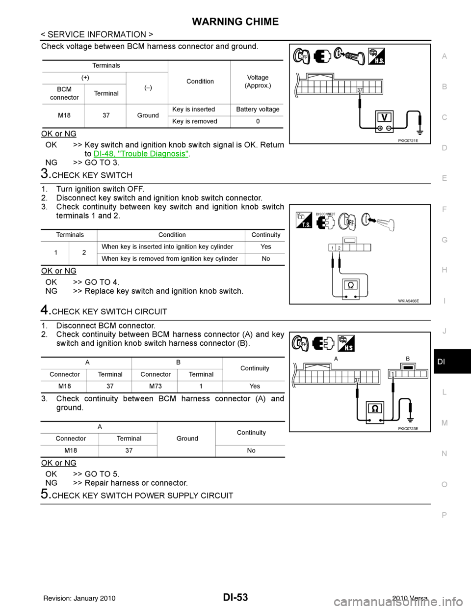
Check voltage between BCM harness connector and ground.
OK or NG
OK >> Key switch and ignition knob switch signal is OK. Return to DI-48, "
Trouble Diagnosis".
NG >> GO TO 3.
3.CHECK KEY SWITCH
1. Turn ignition switch OFF.
2. Disconnect key switch and i gnition knob switch connector.
3. Check continuity between key switch and ignition knob switch
terminals 1 and 2.
OK or NG
OK >> GO TO 4.
NG >> Replace key switch and ignition knob switch.
4.CHECK KEY SWITCH CIRCUIT
1. Disconnect BCM connector.
2. Check continuity between BCM harness connector (A) and key switch and ignition knob switch harness connector (B).
3. Check continuity between BCM harness connector (A) and ground.
OK or NG
OK >> GO TO 5.
NG >> Repair harness or connector.
5.CHECK KEY SWITCH POWER SUPPLY CIRCUIT
Te r m i n a l s ConditionVol tag e
(Approx.)
(+)
(−)
BCM
connector Te r m i n a l
M18 37 Ground Key is inserted Battery voltage
Key is removed
0
PKIC0721E
Terminals ConditionContinuity
12 When key is inserted into ignition key cylinder Yes
When key is removed from ignition key cylinder No
WKIA5466E
AB
Continuity
Connector Terminal Connector Terminal
M183 7M 73 1 Y es
A GroundContinuity
Connector Terminal
M18 37 No
PKIC0723E
Revision: January 20102010 Versa
Page 1264 of 3745
DI-54
< SERVICE INFORMATION >
WARNING CHIME
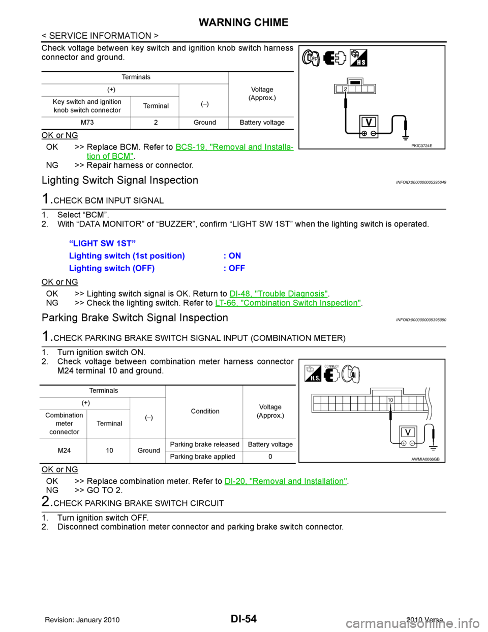
Check voltage between key switch and ignition knob switch harness
connector and ground.
OK or NG
OK >> Replace BCM. Refer to BCS-19, "Removal and Installa-
tion of BCM".
NG >> Repair harness or connector.
Lighting Switch Signal InspectionINFOID:0000000005395049
1.CHECK BCM INPUT SIGNAL
1. Select “BCM”.
2. With “DATA MONITOR” of “BUZZER”, confirm “LIG HT SW 1ST” when the lighting switch is operated.
OK or NG
OK >> Lighting switch signal is OK. Return to DI-48, "Trouble Diagnosis".
NG >> Check the lighting switch. Refer to LT-66, "
Combination Switch Inspection".
Parking Brake Switch Signal InspectionINFOID:0000000005395050
1.CHECK PARKING BRAKE SWITCH SIGNAL INPUT (COMBINATION METER)
1. Turn ignition switch ON.
2. Check voltage between combination meter harness connector M24 terminal 10 and ground.
OK or NG
OK >> Replace combination meter. Refer to DI-20, "Removal and Installation".
NG >> GO TO 2.
2.CHECK PARKING BRAKE SWITCH CIRCUIT
1. Turn ignition switch OFF.
2. Disconnect combination meter connector and parking brake switch connector.
Te r m i n a l s
Vo l ta g e
(Approx.)
(+)
(−)
Key switch and ignition
knob switch connector Te r m i n a l
M73 2Ground Battery voltage
PKIC0724E
“LIGHT SW 1ST”
Lighting switch ( 1st position) : ON
Lighting switch (OFF) : OFF
Te r m i n a l s
ConditionVoltag e
(Approx.)
(+)
(−)
Combination
meter
connector Te r m i n a l
M24 10 Ground Parking brake released Battery voltage
Parking brake applied 0
AWMIA0066GB
Revision: January 20102010 Versa
Page 1265 of 3745
WARNING CHIMEDI-55
< SERVICE INFORMATION >
C
DE
F
G H
I
J
L
M A
B
DI
N
O P
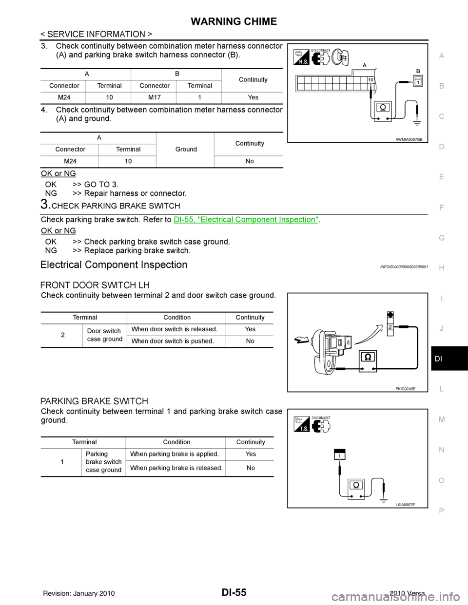
3. Check continuity between combination meter harness connector (A) and parking brake switch harness connector (B).
4. Check continuity between combination meter harness connector (A) and ground.
OK or NG
OK >> GO TO 3.
NG >> Repair harness or connector.
3.CHECK PARKING BRAKE SWITCH
Check parking brake switch. Refer to DI-55, "
Electrical Component Inspection".
OK or NG
OK >> Check parking brake switch case ground.
NG >> Replace parking brake switch.
Electrical Component InspectionINFOID:0000000005395051
FRONT DOOR SWITCH LH
Check continuity between terminal 2 and door switch case ground.
PARKING BRAKE SWITCH
Check continuity between terminal 1 and parking brake switch case
ground.
AB Continuity
Connector Terminal Connector Terminal
M241 0M 17 1 Y es
A GroundContinuity
Connector Terminal
M24 10 No
AWMIA0067GB
TerminalConditionContinuity
2 Door switch
case ground When door switch is released. Yes
When door switch is pushed. No
PKIC0245E
Terminal
ConditionContinuity
1 Parking
brake switch
case ground When parking brake is applied. Yes
When parking brake is released. No
LKIA0907E
Revision: January 20102010 Versa
Page 1357 of 3745
![NISSAN LATIO 2010 Service Repair Manual EC-92
< FUNCTION DIAGNOSIS >[HR16DE]
ON BOARD DIAGNOSTIC (OBD) SYSTEM
WITH GST
1. Turn ignition switch OFF and wait at least 10 seconds.
2. Turn ignition switch ON.
3. Turn ignition switch OFF and wai NISSAN LATIO 2010 Service Repair Manual EC-92
< FUNCTION DIAGNOSIS >[HR16DE]
ON BOARD DIAGNOSTIC (OBD) SYSTEM
WITH GST
1. Turn ignition switch OFF and wait at least 10 seconds.
2. Turn ignition switch ON.
3. Turn ignition switch OFF and wai](/manual-img/5/57358/w960_57358-1356.png)
EC-92
< FUNCTION DIAGNOSIS >[HR16DE]
ON BOARD DIAGNOSTIC (OBD) SYSTEM
WITH GST
1. Turn ignition switch OFF and wait at least 10 seconds.
2. Turn ignition switch ON.
3. Turn ignition switch OFF and wait at least 10 seconds.
4. Turn ignition switch ON.
5. Select Service $0A with GST (Generic Scan Tool).
MALFUNCTION INDICATOR LAMP (MIL)
Description
The MIL is located on the instrument panel.
1. The MIL will light up when the ignition switch is turned ON with-
out the engine running. This is a bulb check.
If the MIL does not light up, refer to EC-439, "
Component Func-
tion Check".
2. When the engine is started, the MIL should go off. If the MIL remains on, the on board diagnostic system has
detected an engine system malfunction.
On Board Diagnostic System Function
The on board diagnostic system has the following three functions.
Diagnostic Test Mode I — Bulb Check
In this mode, the MIL on the instrument panel should st ay ON. If it remains OFF, check the bulb. Refer to EC-
439, "Description".
Diagnostic Test Mode I — Malfunction Warning
SEF217U
Diagnostic Test
ModeKEY and ENG.
Status Function
Explanation of Function
Mode I Ignition switch in
ON position
Engine stopped BULB CHECK
This function checks the MIL bulb for damage (blown, open
circuit, etc.).
If the MIL does not come on, check MIL circuit.
Engine running MALFUNCTION WARNING When a malfunction is detected twice in two consecutive
driving cycles (two trip detection logic), the MIL will light up
to inform the driver that a malfunction has been detected.
The following malfunctions will light up or blink the MIL in
the 1st trip.
• Misfire (Possible three way catalyst damage)
• One trip detection diagnoses
Mode II Ignition switch in
ON position
Engine stopped SELF-DIAGNOSTIC
RESULTS
This function allows DTCs an
d 1st trip DTCs to be read.
Revision: January 20102010 Versa
Page 1358 of 3745
![NISSAN LATIO 2010 Service Repair Manual ON BOARD DIAGNOSTIC (OBD) SYSTEMEC-93
< FUNCTION DIAGNOSIS > [HR16DE]
C
D
E
F
G H
I
J
K L
M A
EC
NP
OThis DTC number is clarified in Diagnostic Test Mode II (SELF-DIAGNOSTIC RESULTS)
Diagnostic Test M NISSAN LATIO 2010 Service Repair Manual ON BOARD DIAGNOSTIC (OBD) SYSTEMEC-93
< FUNCTION DIAGNOSIS > [HR16DE]
C
D
E
F
G H
I
J
K L
M A
EC
NP
OThis DTC number is clarified in Diagnostic Test Mode II (SELF-DIAGNOSTIC RESULTS)
Diagnostic Test M](/manual-img/5/57358/w960_57358-1357.png)
ON BOARD DIAGNOSTIC (OBD) SYSTEMEC-93
< FUNCTION DIAGNOSIS > [HR16DE]
C
D
E
F
G H
I
J
K L
M A
EC
NP
OThis DTC number is clarified in Diagnostic Test Mode II (SELF-DIAGNOSTIC RESULTS)
Diagnostic Test Mode II — Self-diagnostic Results
In this mode, the DTC and 1st trip DTC are indicated
by the number of blinks of the MIL as shown below.
The DTC and 1st trip DTC are displayed at the same time. If the MIL does not illuminate in diagnostic test
mode I (Malfunction warning), all displayed items are 1st trip DTCs. If onl y one code is displayed when the MIL
illuminates in diagnostic test mode II (SELF-DIAGNOSTIC RESULTS), it is a DTC; if two or more codes are
displayed, they may be either DTCs or 1st trip DTCs. DTC No. is same as that of 1st trip DTC. These uniden-
tified codes can be identified by using the CONSULT-II I or GST. A DTC will be used as an example for how to
read a code.
A particular trouble code can be identified by the number of four-digit numeral flashes as per the following.
The length of time the 1,000th-digit numeral flashes on and off is 1.2 seconds consisting of an ON (0.6-sec-
onds) - OFF (0.6-seconds) cycle.
The 100th-digit numeral and lower digit numerals consis t of a 0.3-seconds ON and 0.3-seconds OFF cycle.
A change from one digit numeral to another occurs at an inte rval of 1.0-second OFF. In other words, the later
numeral appears on the display 1.3 seconds after the former numeral has disappeared.
A change from one trouble code to another occurs at an interval of 1.8-seconds OFF.
In this way, all the detected malfunctions are classi fied by their DTC numbers. The DTC 0000 refers to no mal-
function. (See EC-468, "
DTCIndex")
How to Switch Diagnostic Test Mode
NOTE:
•It is better to count the time accurately with a clock.
MIL Condition
ON When the malfunction is detected.
OFF No malfunction.
JMBIA1140GB
Number 0 123456789 A B C D E F
Flashes 10 123456789 11 12 13 14 15 16
Revision: January 20102010 Versa