2010 NISSAN LATIO turn signal
[x] Cancel search: turn signalPage 623 of 3745
BL-114
< SERVICE INFORMATION >
INTELLIGENT KEY SYSTEM
435R Back door switch Input OFFON (open) 0V
OFF (closed)
Battery voltage
44
5LG Rear wiper auto stop Input ON Rear wiper operating 0
Rear wiper stopped
Battery
45
7GR Lock switch Input OFFON (lock)
0V
OFF Battery voltage
46
7L Unlock switch Input OFFON (unlock)
0V
OFF Battery voltage
47 BR Front door switch LH Input OFF ON (open)
0V
OFF (closed) Battery voltage
48 O Rear door switch LH Input OFF ON (open)
0V
OFF (closed) Battery voltage
49 P Luggage room lamp Output OFF Any door open (ON)
0V
All doors closed (OFF) Battery voltage
50 SB A/C indicator Output ONA/C OFF
0
A/C ON Battery voltage
53
5R Back door lock assem-
bly (actuator)
Output OFF Back door (open)
Battery voltage
53
6R Trunk lamp switch and
trunk release solenoid Output OFF Trunk lid (open)
Battery voltage
55
5V Rear wiper motor out-
put
Output ONOFF
0
ON Battery voltage
56 R Battery saver output Output OFF
30 minutes after ignition
switch is turned OFF 0V
ON — Battery voltage
57 LG Battery power supply Input OFF —Battery voltage
59
7G Front door lock actua-
tor LH (unlock) Output OFFOFF (neutral)
0V
ON (unlock) Battery voltage
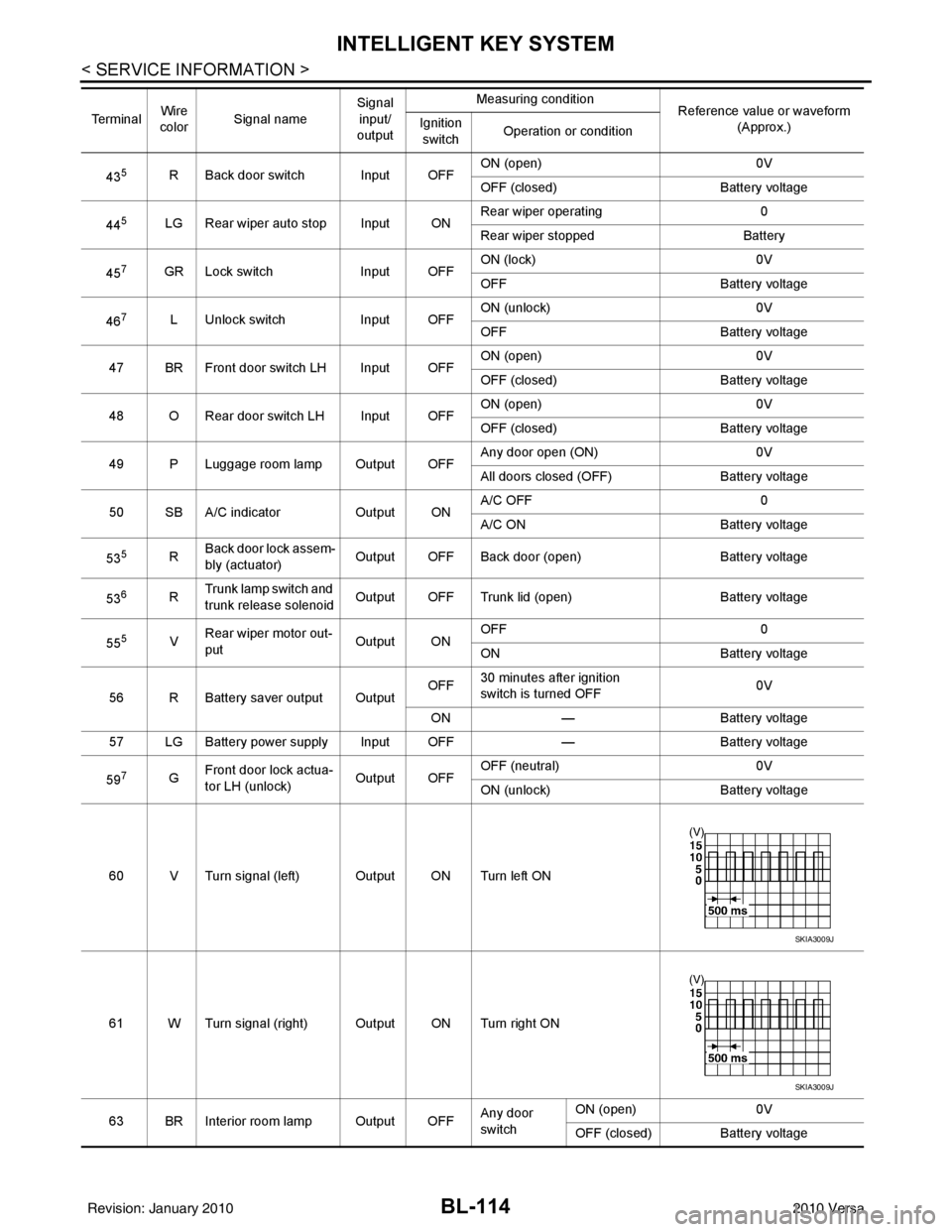
60 V Turn signal (left) Output ON Turn left ON
61 W Turn signal (right) Output ON Turn right ON
63 BR Interior room lamp Output OFF Any door
switchON (open)
0V
OFF (closed) Battery voltage
Te r m i n a l
Wire
color Signal name Signal
input/
output Measuring condition
Reference value or waveform
(Approx.)
Ignition
switch Operation or condition
SKIA3009J
SKIA3009J
Revision: January 20102010 Versa
Page 626 of 3745
INTELLIGENT KEY SYSTEMBL-117
< SERVICE INFORMATION >
C
DE
F
G H
J
K L
M A
B
BL
N
O P
• Intelligent Key button
OK or NG
OK >> GO TO 6
NG >> Refer to BL-119, "
Trouble Diagnosis Symptom Chart".
6.CHECK WARNING CHIME FUNCTION
Check if warning chime function operates normally according to system description. Refer to BL-88, "
System
Description".
OK or NG
OK >> GO TO 7
NG >> Refer to BL-119, "
Trouble Diagnosis Symptom Chart".
7.CHECK WARNING LAMP FUNCTION
Check if warning lamp could be turn on normally according to system description. Refer to BL-88, "
System
Description".
OK or NG
OK >> Inspection End.
NG >> Refer to BL-119, "
Trouble Diagnosis Symptom Chart".
CONSULT-III Functions (INTELLIGENT KEY)INFOID:0000000005396609
CONSULT-III can display each diagnostic item using the diagnostic test modes as shown below.
CONSULT-III Application ItemINFOID:0000000005396610
SELF-DIAGNOSTIC RESULTS
DATA MONITOR
Diagnostic mode Description
WORK SUPPORT Changes settings for each function.
SELF DIAGNOSTIC RESULT Intelligent Key unit performs CAN communication diagnosis. DATA MONITOR Displays Intelligent Key unit input data in real time.
CAN DIAG SUPPORT MNTR The results of transmit/receive diagnosis of CAN Communication can be read. ACTIVE TEST Operation of electrical loads can be checked by sending driving signal to them.
ECU IDENTIFICATION Displays In telligent Key unit part No.
Self-diag resultsDescription Diagnosis procedureReference page
CAN COMM Malfunction is detected in CAN co mmunication. Check CAN communication system. BL-126
CAN COMM2 Intelligent Key unit internal malfunction Check CAN communication system.BL-126
STRG COMMMalfunction is detected in communication of Intelli-
gent Key unit and steering lock solenoid.
Check steering lock solenoid.
BL-147
I-KEY C/UIntelligent Key unit internal ma lfunctionReplace Intelligent Key unit. BL-158
IMMUNATS malfunction Check NATS.BL-248
Monitor item Content
PUSH SW Indicates [ON/OFF] condition of ignition knob switch.
KEY SW Indicates [ON/OFF] condition of key switch.
DR REQ SW Indicates [ON/OFF] condition of door request switch (driver side).
AS REQ SW Indicates [ON/OFF] condition of door request switch (passenger side).
BD/TR REQ SW Indicates [ON/OFF] condition of back door request switch.
IGN SW Indicates [ON/OFF] condition of ignition switch in ON position.
ACC SW Indicates [ON/OFF] condition of ignition switch in ACC position.
Revision: January 20102010 Versa
Page 636 of 3745
INTELLIGENT KEY SYSTEMBL-127
< SERVICE INFORMATION >
C
DE
F
G H
J
K L
M A
B
BL
N
O P
OK or NG
OK >> Power supply and ground circuits are OK.
NG >> Repair or replace the Intelligent Key unit ground circuit.
Key Switch (Intelligent Key Unit Input) CheckINFOID:0000000005396614
1.CHECK KEY SWITCH INPUT SIGNAL
With CONSULT-III
Check key switch (“KEY SW”) in “DATA MONITOR” mode with CONSULT-III.
Without CONSULT-III
1. Turn ignition switch OFF.
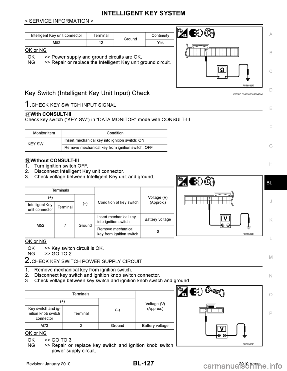
2. Disconnect Intelligent Key unit connector.
3. Check voltage between Intelligent Key unit and ground.
OK or NG
OK >> Key switch circuit is OK.
NG >> GO TO 2
2.CHECK KEY SWITCH POWER SUPPLY CIRCUIT
1. Remove mechanical key from ignition switch.
2. Disconnect key switch and i gnition knob switch connector.
3. Check voltage between key switch and ignition knob switch and ground.
OK or NG
OK >> GO TO 3
NG >> Repair or replace key switch and ignition knob switch power supply circuit.
Intelligent Key unit connector Terminal GroundContinuity
M52 12 Yes
PIIB6596E
Monitor item Condition
KEY SW Insert mechanical key into ignition switch: ON
Remove mechanical key from ignition switch: OFF
Te r m i n a l s
Condition of key switch Voltage (V)
(Approx.)
(+)
(–)
Intelligent Key
unit connector Te r m i n a l
M52 7 Ground Insert mechanical key
into ignition switch
Battery voltage
Remove mechanical
key from ignition switch 0
PIIB6597E
Te r m i n a l s
Voltage (V)(Approx.)
(+)
(–)
Key switch and ig-
nition knob switch
connector Te r m i n a l
M73 2Ground Battery voltage
PIIB6598E
Revision: January 20102010 Versa
Page 638 of 3745
INTELLIGENT KEY SYSTEMBL-129
< SERVICE INFORMATION >
C
DE
F
G H
J
K L
M A
B
BL
N
O P
OK or NG
OK >> GO TO 3
NG >> Replace key cylinder assembly (built-in key switch).
3.CHECK KEY SWITCH CIRCUIT
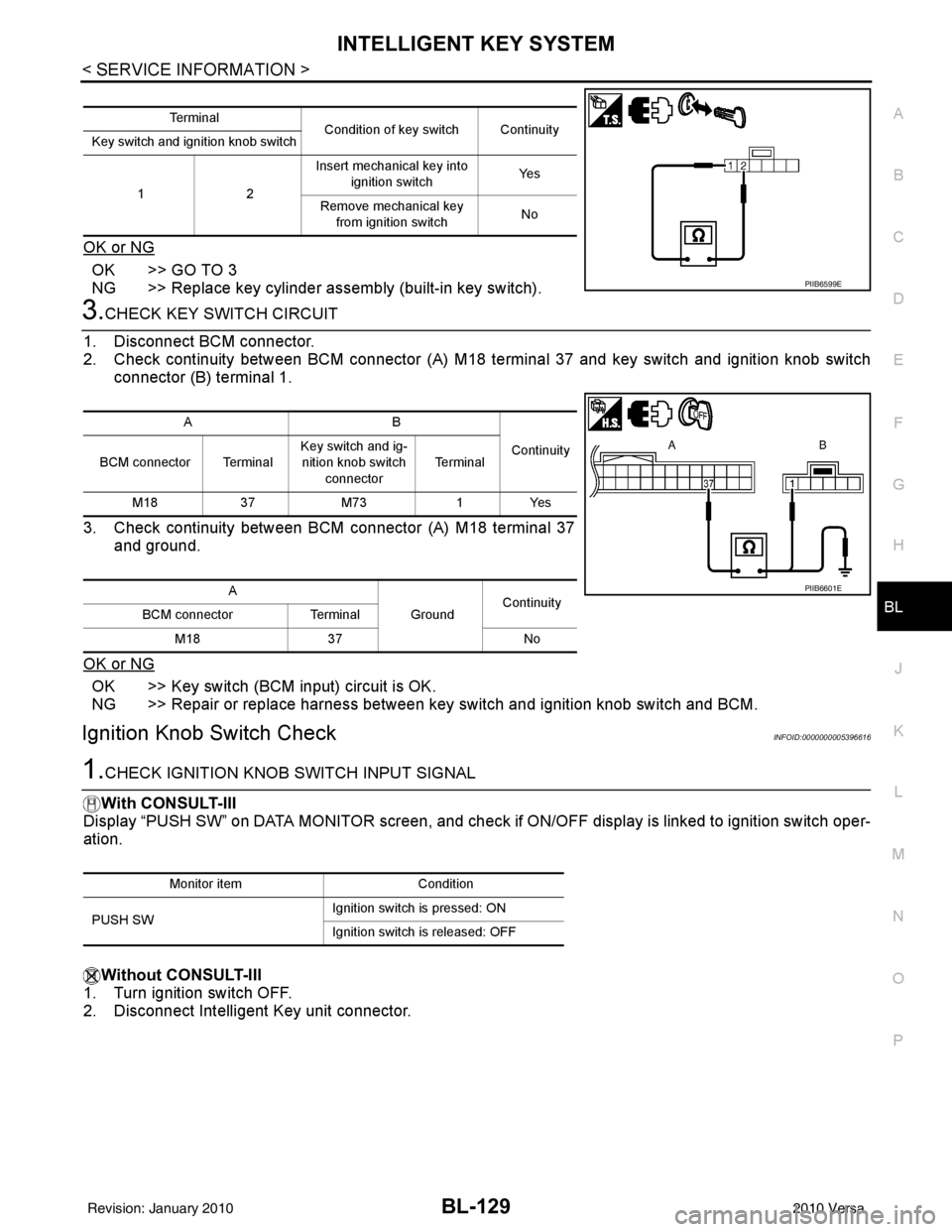
1. Disconnect BCM connector.
2. Check continuity between BCM connector (A) M18 terminal 37 and key switch and ignition knob switch
connector (B) terminal 1.
3. Check continuity between BCM connector (A) M18 terminal 37 and ground.
OK or NG
OK >> Key switch (BCM input) circuit is OK.
NG >> Repair or replace harness between key switch and ignition knob switch and BCM.
Ignition Knob Switch CheckINFOID:0000000005396616
1.CHECK IGNITION KNOB SWITCH INPUT SIGNAL
With CONSULT-III
Display “PUSH SW” on DATA MONITOR screen, and check if ON/OFF display is linked to ignition switch oper-
ation.
Without CONSULT-III
1. Turn ignition switch OFF.
2. Disconnect Intelligent Key unit connector.
Te r m i n a l Condition of key switch Continuity
Key switch and ignition knob switch
12 Insert mechanical key into
ignition switch Ye s
Remove mechanical key from ignition switch No
PIIB6599E
AB
Continuity
BCM connector Terminal Key switch and ig-
nition knob switch
connector Te r m i n a l
M18 37M73 1Yes
A GroundContinuity
BCM connector Terminal
M18 37 No
PIIB6601E
Monitor item Condition
PUSH SW Ignition switch is pressed: ON
Ignition switch is released: OFF
Revision: January 20102010 Versa
Page 647 of 3745
BL-138
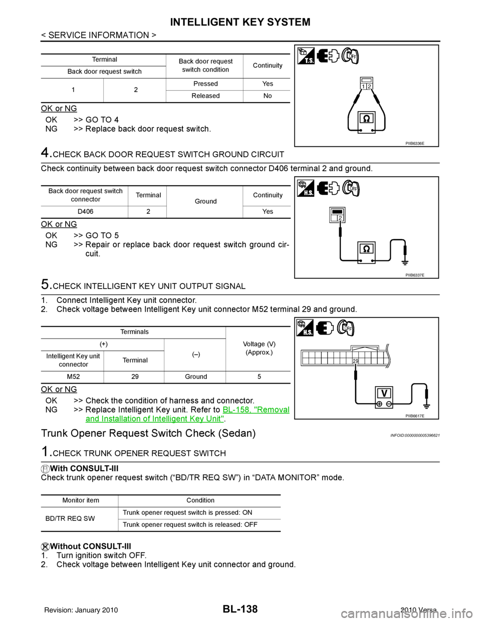
< SERVICE INFORMATION >
INTELLIGENT KEY SYSTEM
OK or NG
OK >> GO TO 4
NG >> Replace back door request switch.
4.CHECK BACK DOOR REQUEST SWITCH GROUND CIRCUIT
Check continuity between back door request switch connector D406 terminal 2 and ground.
OK or NG
OK >> GO TO 5
NG >> Repair or replace back door request switch ground cir- cuit.
5.CHECK INTELLIGENT KEY UNIT OUTPUT SIGNAL
1. Connect Intelligent Key unit connector.
2. Check voltage between Intelligent Key unit connector M52 terminal 29 and ground.
OK or NG
OK >> Check the condition of harness and connector.
NG >> Replace Intelligent Key unit. Refer to BL-158, "
Removal
and Installation of Intelligent Key Unit".
Trunk Opener Request Switch Check (Sedan)INFOID:0000000005396621
1.CHECK TRUNK OPENER REQUEST SWITCH
With CONSULT-III
Check trunk opener request switch (“BD/TR REQ SW”) in “DATA MONITOR” mode.
Without CONSULT-III
1. Turn ignition switch OFF.
2. Check voltage between Intelligent Key unit connector and ground.
Te r m i n a l Back door request
switch condition Continuity
Back door request switch
12 Pressed Yes
Released No
PIIB6336E
Back door request switch connector Te r m i n a l
GroundContinuity
D406 2 Yes
PIIB6337E
Te r m i n a l s
Voltage (V)(Approx.)
(+)
(–)
Intelligent Key unit
connector Te r m i n a l
M52 29Ground 5
PIIB6617E
Monitor item Condition
BD/TR REQ SW Trunk opener request switch is pressed: ON
Trunk opener request switch is released: OFF
Revision: January 20102010 Versa
Page 649 of 3745

BL-140
< SERVICE INFORMATION >
INTELLIGENT KEY SYSTEM
OK or NG
OK >> GO TO 5
NG >> Repair or replace trunk opener request switch groundcircuit.
5.CHECK INTELLIGENT KEY UNIT OUTPUT SIGNAL
1. Connect Intelligent Key unit connector.
2. Check voltage between Intelligent Key unit connector M52 terminal 29 and ground.
OK or NG
OK >> Check the condition of harness and connector.
NG >> Replace Intelligent Key unit. Refer to BL-158, "
Removal
and Installation of Intelligent Key Unit".
Unlock Sensor CheckINFOID:0000000005396622
1.CHECK UNLOCK SENSOR INPUT SIGNAL
Check voltage between Intelligent Key unit connector and ground.
OK or NG
OK >> Unlock sensor circuit is OK.
NG >> GO TO 2
2.CHECK UNLOCK SENSOR CIRCUIT
1. Turn ignition switch OFF.
2. Disconnect Intelligent Key unit and front door lock actuator LH (door unlock sensor) connector.
3. Check continuity between Intelligent Key unit connec tor (A) terminal 28 and front door lock actuator LH
(door unlock sensor) connector (B) terminal 4.
Trunk opener request
switch connector Te r m i n a l
GroundContinuity
B129 2 Yes
PIIB6337E
Te r m i n a l s
Voltage (V)(Approx.)
(+)
(–)
Intelligent Key unit
connector Te r m i n a l
M52 29Ground 5
PIIB6617E
Te r m i n a l s
Front door
lock
(driver side)
condition Voltage (V)
(Approx.)
(+)
(–)
Intelligent Key
unit connector Te r m i n a l
M52 28Ground Locked
5
Unlocked 0
PIIB6638E
Revision: January 20102010 Versa
Page 652 of 3745
INTELLIGENT KEY SYSTEMBL-143
< SERVICE INFORMATION >
C
DE
F
G H
J
K L
M A
B
BL
N
O P
OK or NG
OK >> Intelligent Key warning buzzer is OK.
NG >> Replace inoperative Intelligent Key warning buzzer.
Outside Key Antenna (Driver Si de and Passenger Side) CheckINFOID:0000000005396624
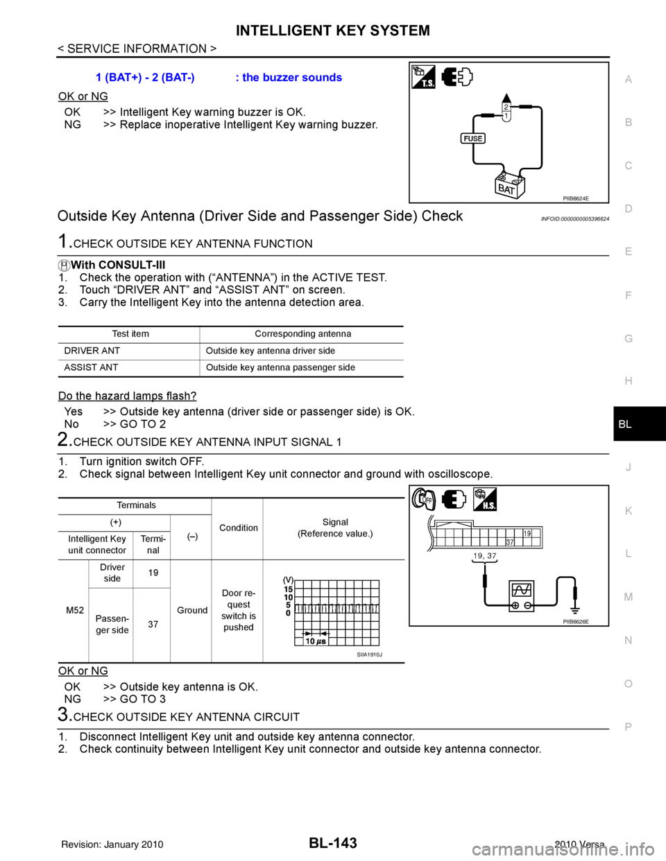
1.CHECK OUTSIDE KEY ANTENNA FUNCTION
With CONSULT-III
1. Check the operation with (“ANT ENNA”) in the ACTIVE TEST.
2. Touch “DRIVER ANT” and “ASSIST ANT” on screen.
3. Carry the Intelligent Key into the antenna detection area.
Do the hazard lamps flash?
Yes >> Outside key antenna (driver side or passenger side) is OK.
No >> GO TO 2
2.CHECK OUTSIDE KEY ANTENNA INPUT SIGNAL 1
1. Turn ignition switch OFF.
2. Check signal between Intelligent Key unit connector and ground with oscilloscope.
OK or NG
OK >> Outside key antenna is OK.
NG >> GO TO 3
3.CHECK OUTSIDE KEY ANTENNA CIRCUIT
1. Disconnect Intelligent Key unit and outside key antenna connector.
2. Check continuity between Intelligent Key unit connector and outside key antenna connector. 1 (BAT+) - 2 (BAT-) : the buzzer sounds
PIIB6624E
Test item
Corresponding antenna
DRIVER ANT Outside key antenna driver side
ASSIST ANT Outside key antenna pass enger side
Te r m i n a l s
Condition Signal
(Reference value.)
(+)
(–)
Intelligent Key
unit connector Te r m i -
nal
M52 Driver
side 19
Ground Door re-
quest
switch is pushed
Passen-
ger side 37
PIIB6626E
SIIA1910J
Revision: January 20102010 Versa
Page 654 of 3745
INTELLIGENT KEY SYSTEMBL-145
< SERVICE INFORMATION >
C
DE
F
G H
J
K L
M A
B
BL
N
O P
Do the hazard lamps flash?
Yes >> Rear bumper antenna is OK.
No >> GO TO 2
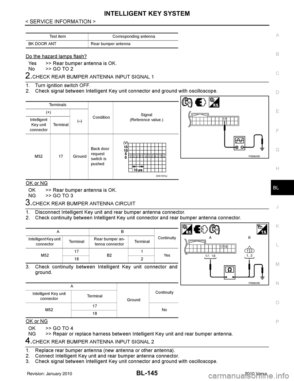
2.CHECK REAR BUMPER ANTENNA INPUT SIGNAL 1
1. Turn ignition switch OFF.
2. Check signal between Intelligent Key unit connector and ground with oscilloscope.
OK or NG
OK >> Rear bumper antenna is OK.
NG >> GO TO 3
3.CHECK REAR BUMPER ANTENNA CIRCUIT
1. Disconnect Intelligent Key unit and rear bumper antenna connector.
2. Check continuity between Intelligent Key unit connector and rear bumper antenna connector.
3. Check continuity between Intelligent Key unit connector and ground.
OK or NG
OK >> GO TO 4
NG >> Repair or replace harness between Intelligent Key unit and rear bumper antenna.
4.CHECK REAR BUMPER ANTENNA INPUT SIGNAL 2
1. Replace rear bumper antenna (new antenna or other antenna).
2. Connect Intelligent Key unit and rear bumper antenna connector.
3. Check signal between Intelligent Key unit connector and ground with oscilloscope.
Test item Corresponding antenna
BK DOOR ANT Rear bumper antenna
Te r m i n a l s
Condition Signal
(Reference value.)
(+)
(–)
Intelligent
Key unit
connector Te r m i n a l
M52 17 Ground Back door
request
switch is
pushed
PIIB6628E
SIIA1910J
AB
Continuity
Intelligent Key unit
connector Te r m i n a l
Rear bumper an-
tenna connector Te r m i n a l
M52 17
B2 1
Ye s
18 2
A GroundContinuity
Intelligent Key unit
connector Te r m i n a l
M52 17
No
18
PIIB6629E
Revision: January 20102010 Versa