2010 NISSAN LATIO turn signal
[x] Cancel search: turn signalPage 655 of 3745
BL-146
< SERVICE INFORMATION >
INTELLIGENT KEY SYSTEM
OK or NG
OK >> Replace rear bumper antenna.
NG >> Replace Intelligent Key unit. Refer to BL-158, "
Removal and Installation of Intelligent Key Unit".
Inside Key Antenna CheckINFOID:0000000005396626
1.CHECK INSIDE KEY ANTENNA INPUT SIGNAL 1
1. Turn ignition switch OFF.
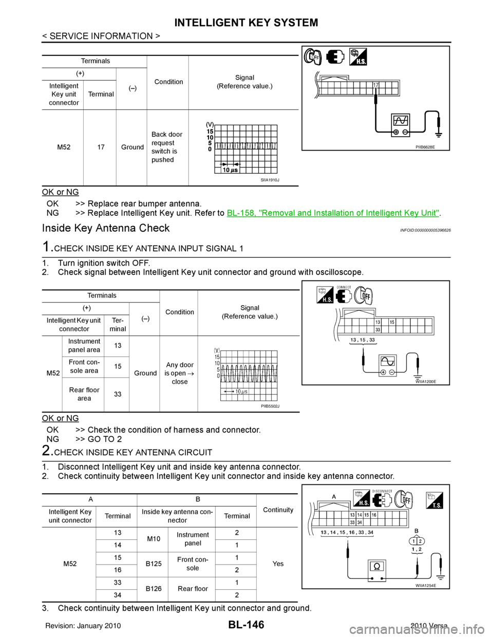
2. Check signal between Intelligent Key unit connector and ground with oscilloscope.
OK or NG
OK >> Check the condition of harness and connector.
NG >> GO TO 2
2.CHECK INSIDE KEY ANTENNA CIRCUIT
1. Disconnect Intelligent Key unit and inside key antenna connector.
2. Check continuity between Intelligent Key unit connector and inside key antenna connector.
3. Check continuity between Intelligent Key unit connector and ground.
Te r m i n a l s
Condition Signal
(Reference value.)
(+)
(–)
Intelligent
Key unit
connector Te r m i n a l
M52 17 Ground Back door
request
switch is
pushed
PIIB6628E
SIIA1910J
Te r m i n a l s
ConditionSignal
(Reference value.)
(+)
(–)
Intelligent Key unit
connector Te r -
minal
M52 Instrument
panel area 13
Ground Any door
is open →
close
Front con-
sole area 15
Rear floor area 33
WIIA1200E
PIIB5502J
AB
Continuity
Intelligent Key
unit connector Te r m i n a lInside key antenna con-
nector Te r m i n a l
M52 13
M10Instrument
panel 2
Ye s
14
1
15 B125Front con-
sole 1
16 2
33 B126 Rear floor 1
34 2
WIIA1254E
Revision: January 20102010 Versa
Page 656 of 3745
INTELLIGENT KEY SYSTEMBL-147
< SERVICE INFORMATION >
C
DE
F
G H
J
K L
M A
B
BL
N
O P
OK or NG
OK >> GO TO 3
NG >> Repair or replace harness between Intelligent Key unit and inside key antenna.
3.CHECK INSIDE KEY ANTENNA INPUT SIGNAL 2
1. Replace inside key antenna. (New antenna or other antenna)
2. Connect Intelligent Key unit and inside key antenna connector.
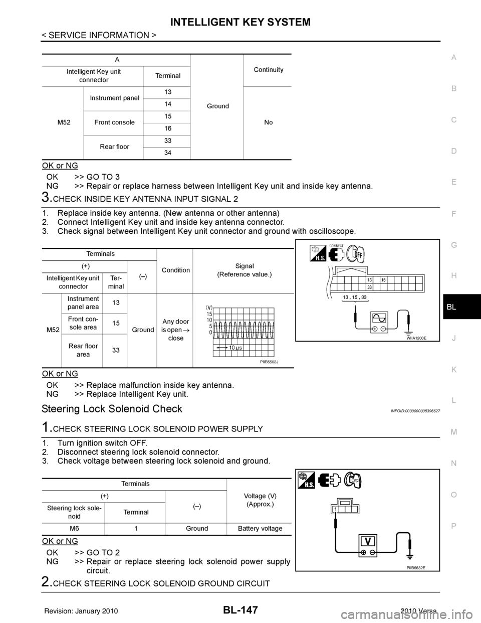
3. Check signal between Intelligent Key unit connector and ground with oscilloscope.
OK or NG
OK >> Replace malfunction inside key antenna.
NG >> Replace Intelligent Key unit.
Steering Lock Solenoid CheckINFOID:0000000005396627
1.CHECK STEERING LOCK SOLENOID POWER SUPPLY
1. Turn ignition switch OFF.
2. Disconnect steering lock solenoid connector.
3. Check voltage between steering lock solenoid and ground.
OK or NG
OK >> GO TO 2
NG >> Repair or replace steering lock solenoid power supply circuit.
2.CHECK STEERING LOCK SOLENOID GROUND CIRCUIT
A
GroundContinuity
Intelligent Key unit
connector Te r m i n a l
M52 Instrument panel
13
No
14
Front console 15
16
Rear floor 33
34
Te r m i n a l s
ConditionSignal
(Reference value.)
(+)
(–)
Intelligent Key unit
connector Te r -
minal
M52 Instrument
panel area 13
Ground Any door
is open →
close
Front con-
sole area 15
Rear floor area 33
WIIA1200E
PIIB5502J
Te r m i n a l s
Voltage (V)(Approx.)
(+)
(–)
Steering lock sole-
noid Te r m i n a l
M6 1Ground Battery voltage
PIIB6632E
Revision: January 20102010 Versa
Page 659 of 3745
BL-150
< SERVICE INFORMATION >
INTELLIGENT KEY SYSTEM
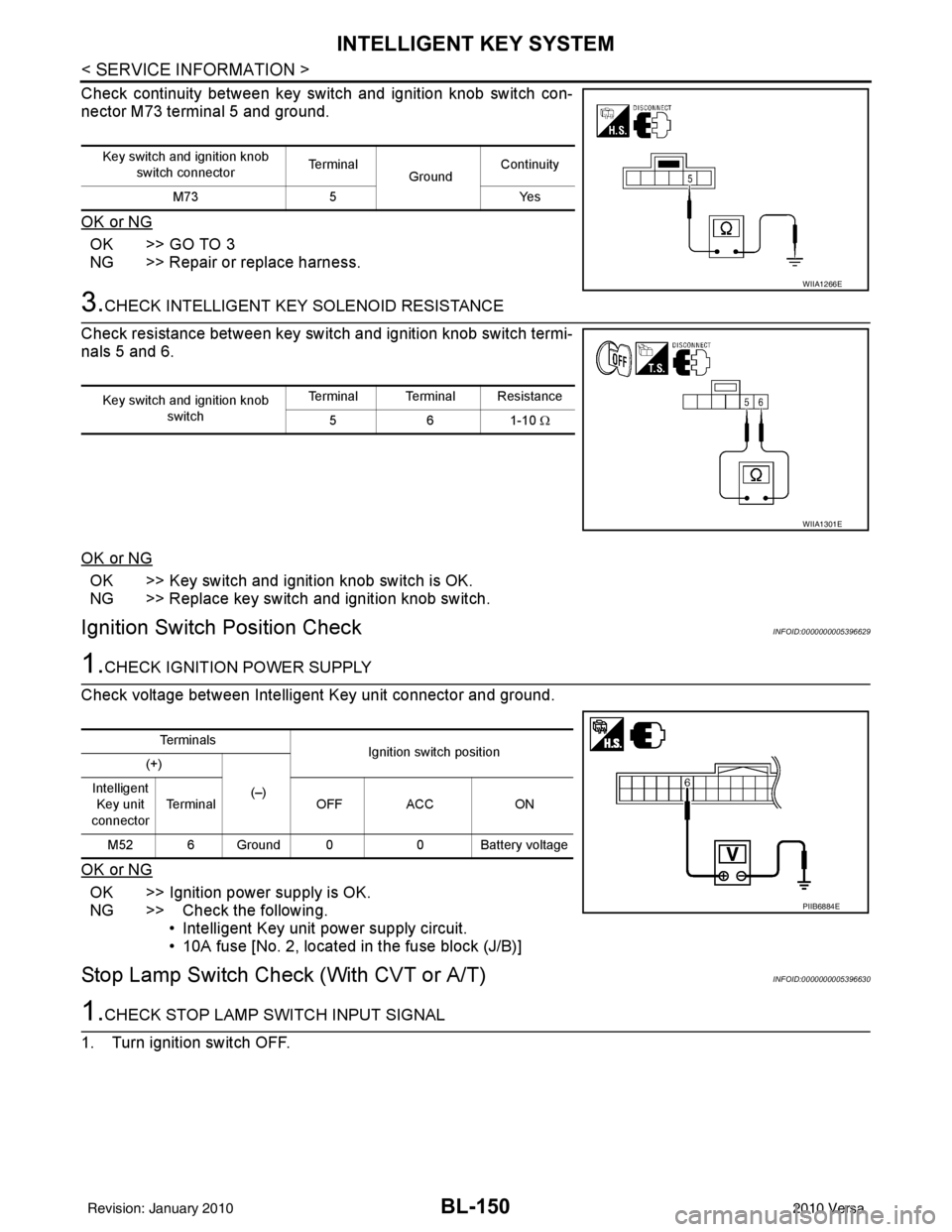
Check continuity between key switch and ignition knob switch con-
nector M73 terminal 5 and ground.
OK or NG
OK >> GO TO 3
NG >> Repair or replace harness.
3.CHECK INTELLIGENT KEY SOLENOID RESISTANCE
Check resistance between key switch and ignition knob switch termi-
nals 5 and 6.
OK or NG
OK >> Key switch and ignition knob switch is OK.
NG >> Replace key switch and ignition knob switch.
Ignition Switch Position CheckINFOID:0000000005396629
1.CHECK IGNITION POWER SUPPLY
Check voltage between Intelligent Key unit connector and ground.
OK or NG
OK >> Ignition power supply is OK.
NG >> Check the following. • Intelligent Key unit power supply circuit.
• 10A fuse [No. 2, located in the fuse block (J/B)]
Stop Lamp Switch Check (With CVT or A/T)INFOID:0000000005396630
1.CHECK STOP LAMP SWITCH INPUT SIGNAL
1. Turn ignition switch OFF.
Key switch and ignition knob switch connector Te r m i n a l
GroundContinuity
M73 5 Yes
WIIA1266E
Key switch and ignition knob
switch Terminal Terminal Resistance
561-10 Ω
WIIA1301E
Te r m i n a l s
Ignition switch position
(+)
(–)
Intelligent
Key unit
connector Terminal
OFF ACC ON
M52 6 Ground 0 0 Battery voltage
PIIB6884E
Revision: January 20102010 Versa
Page 661 of 3745
BL-152
< SERVICE INFORMATION >
INTELLIGENT KEY SYSTEM
Stop Lamp Switch Check (With M/T)
INFOID:0000000005396631
1.CHECK STOP LAMP SWITCH INPUT SIGNAL
1. Turn ignition switch OFF.
2. Disconnect Intelligent Key unit connector.
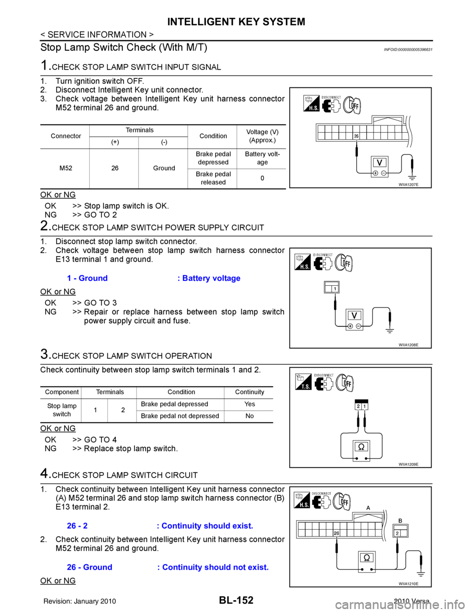
3. Check voltage between Intelligent Key unit harness connector M52 terminal 26 and ground.
OK or NG
OK >> Stop lamp switch is OK.
NG >> GO TO 2
2.CHECK STOP LAMP SWIT CH POWER SUPPLY CIRCUIT
1. Disconnect stop lamp switch connector.
2. Check voltage between stop lamp switch harness connector E13 terminal 1 and ground.
OK or NG
OK >> GO TO 3
NG >> Repair or replace harness between stop lamp switch power supply circuit and fuse.
3.CHECK STOP LAMP SWITCH OPERATION
Check continuity between stop lamp switch terminals 1 and 2.
OK or NG
OK >> GO TO 4
NG >> Replace stop lamp switch.
4.CHECK STOP LAMP SWITCH CIRCUIT
1. Check continuity between Inte lligent Key unit harness connector
(A) M52 terminal 26 and stop lamp switch harness connector (B)
E13 terminal 2.
2. Check continuity between Inte lligent Key unit harness connector
M52 terminal 26 and ground.
OK or NG
Connector Te r m i n a l s
ConditionVoltage (V)
(Approx.)
(+) (-)
M52 26Ground Brake pedal
depressed Battery volt-
age
Brake pedal released 0
WIIA1207E
1 - Ground
: Battery voltage
WIIA1208E
Component Terminals ConditionContinuity
St op la mp switch 12 Brake pedal depressed
Yes
Brake pedal not depressed No
WIIA1209E
26 - 2 : Continuity should exist.
26 - Ground : Continuity should not exist.
WIIA1210E
Revision: January 20102010 Versa
Page 662 of 3745
INTELLIGENT KEY SYSTEMBL-153
< SERVICE INFORMATION >
C
DE
F
G H
J
K L
M A
B
BL
N
O P
OK >> Check condition of harness and connector.
NG >> Repair or replace harness.
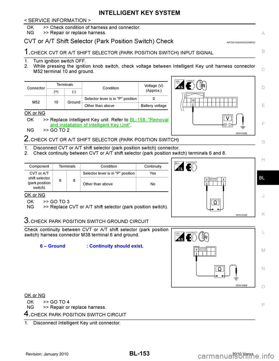
CVT or A/T Shift Se lector (Park Position Switch) CheckINFOID:0000000005396632
1.CHECK CVT OR A/T SHIFT SELECTOR (PARK POSITION SWITCH) INPUT SIGNAL
1. Turn ignition switch OFF.
2. While pressing the ignition knob switch, check voltage between Intelligent Key unit harness connector M52 terminal 10 and ground.
OK or NG
OK >> Replace Intelligent Key unit. Refer to BL-158, "Removal
and Installation of Intelligent Key Unit".
NG >> GO TO 2
2.CHECK CVT OR A/T SHIFT SELECTOR (PARK POSITION SWITCH)
1. Disconnect CVT or A/T shift select or (park position switch) connector.
2. Check continuity between CVT or A/T shift selector (park position switch) terminals 6 and 8.
OK or NG
OK >> GO TO 3
NG >> Replace CVT or A/T shift selector (park position switch).
3.CHECK PARK POSITION SWITCH GROUND CIRCUIT
Check continuity between CVT or A/T shift selector (park position
switch) harness connector M38 terminal 6 and ground.
OK or NG
OK >> GO TO 4
NG >> Repair or replace harness.
4.CHECK PARK POSITION SWITCH CIRCUIT
1. Disconnect Intelligent Key unit connector.
Connector Te r m i n a l s
ConditionVoltage (V)
(Approx.)
(+) (-)
M52 10 Ground Selector lever is in "P" position 0
Other than above
Battery voltage
WIIA1258E
Component Terminals ConditionContinuity
CVT or A/T
shift selector
(park position switch) 68Selector lever is in "P" position Yes
Other than above
No
WIIA1259E
6 – Ground : Continuity should exist.
WIIA1260E
Revision: January 20102010 Versa
Page 663 of 3745
BL-154
< SERVICE INFORMATION >
INTELLIGENT KEY SYSTEM
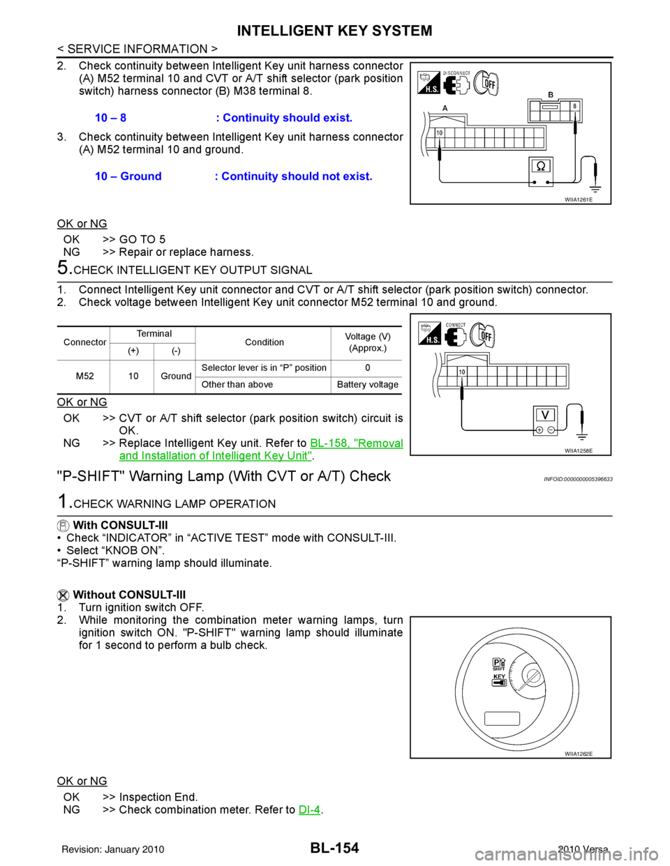
2. Check continuity between Intelligent Key unit harness connector
(A) M52 terminal 10 and CVT or A/T shift selector (park position
switch) harness connector (B) M38 terminal 8.
3. Check continuity between Inte lligent Key unit harness connector
(A) M52 terminal 10 and ground.
OK or NG
OK >> GO TO 5
NG >> Repair or replace harness.
5.CHECK INTELLIGENT KEY OUTPUT SIGNAL
1. Connect Intelligent Key unit connector and CVT or A/T shift selector (park position switch) connector.
2. Check voltage between Intelligent Key unit connector M52 terminal 10 and ground.
OK or NG
OK >> CVT or A/T shift selector (park position switch) circuit is
OK.
NG >> Replace Intelligent Key unit. Refer to BL-158, "
Removal
and Installation of Intelligent Key Unit".
"P-SHIFT" Warning Lamp (With CVT or A/T) CheckINFOID:0000000005396633
1.CHECK WARNING LAMP OPERATION
With CONSULT-III
• Check “INDICATOR” in “ACTIVE TEST” mode with CONSULT-III.
• Select “KNOB ON”.
“P-SHIFT” warning lamp should illuminate.
Without CONSULT-III
1. Turn ignition switch OFF.
2. While monitoring the combination meter warning lamps, turn
ignition switch ON. "P-SHIFT" warning lamp should illuminate
for 1 second to perform a bulb check.
OK or NG
OK >> Inspection End.
NG >> Check combination meter. Refer to DI-4
.
10 – 8 : Continuity should exist.
10 – Ground : Continuity should not exist.
WIIA1261E
Connector
Te r m i n a l
ConditionVoltage (V)
(Approx.)
(+) (-)
M52 10 Ground Selector lever is in “P” position 0
Other than above
Battery voltage
WIIA1258E
WIIA1262E
Revision: January 20102010 Versa
Page 666 of 3745
INTELLIGENT KEY SYSTEMBL-157
< SERVICE INFORMATION >
C
DE
F
G H
J
K L
M A
B
BL
N
O P
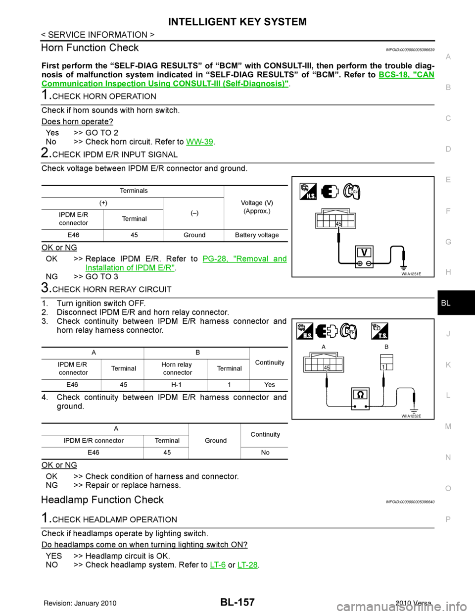
Horn Function CheckINFOID:0000000005396639
First perform the “SELF-DIAG RESULTS” of “BCM” with CONSULT-III, then perform the trouble diag-
nosis of malfunction system indicated in “SELF-DIAG RESULTS” of “BCM”. Refer to BCS-18, "
CAN
Communication Inspection Using CONSULT-III (Self-Diagnosis)".
1.CHECK HORN OPERATION
Check if horn sounds with horn switch.
Does horn operate?
Yes >> GO TO 2
No >> Check horn circuit. Refer to WW-39
.
2.CHECK IPDM E/R INPUT SIGNAL
Check voltage between IPDM E/R connector and ground.
OK or NG
OK >> Replace IPDM E/R. Refer to PG-28, "Removal and
Installation of IPDM E/R".
NG >> GO TO 3
3.CHECK HORN RERAY CIRCUIT
1. Turn ignition switch OFF.
2. Disconnect IPDM E/R and horn relay connector.
3. Check continuity between IPDM E/R harness connector and horn relay harness connector.
4. Check continuity between IPDM E/R harness connector and ground.
OK or NG
OK >> Check condition of harness and connector.
NG >> Repair or replace harness.
Headlamp Function CheckINFOID:0000000005396640
1.CHECK HEADLAMP OPERATION
Check if headlamps operate by lighting switch.
Do headlamps come on when turning lighting switch ON?
YES >> Headlamp circuit is OK.
NO >> Check headlamp system. Refer to LT- 6
or LT- 2 8.
Te r m i n a l s
Voltage (V)(Approx.)
(+)
(–)
IPDM E/R
connector Te r m i n a l
E46 45Ground Ba ttery voltage
WIIA1251E
AB
Continuity
IPDM E/R
connector Te r m i n a l
Horn relay
connector Te r m i n a l
E46 45H-1 1Yes
A GroundContinuity
IPDM E/R connector Terminal
E46 45 No
WIIA1252E
Revision: January 20102010 Versa
Page 684 of 3745
BACK DOOR LOCKBL-175
< SERVICE INFORMATION >
C
DE
F
G H
J
K L
M A
B
BL
N
O P
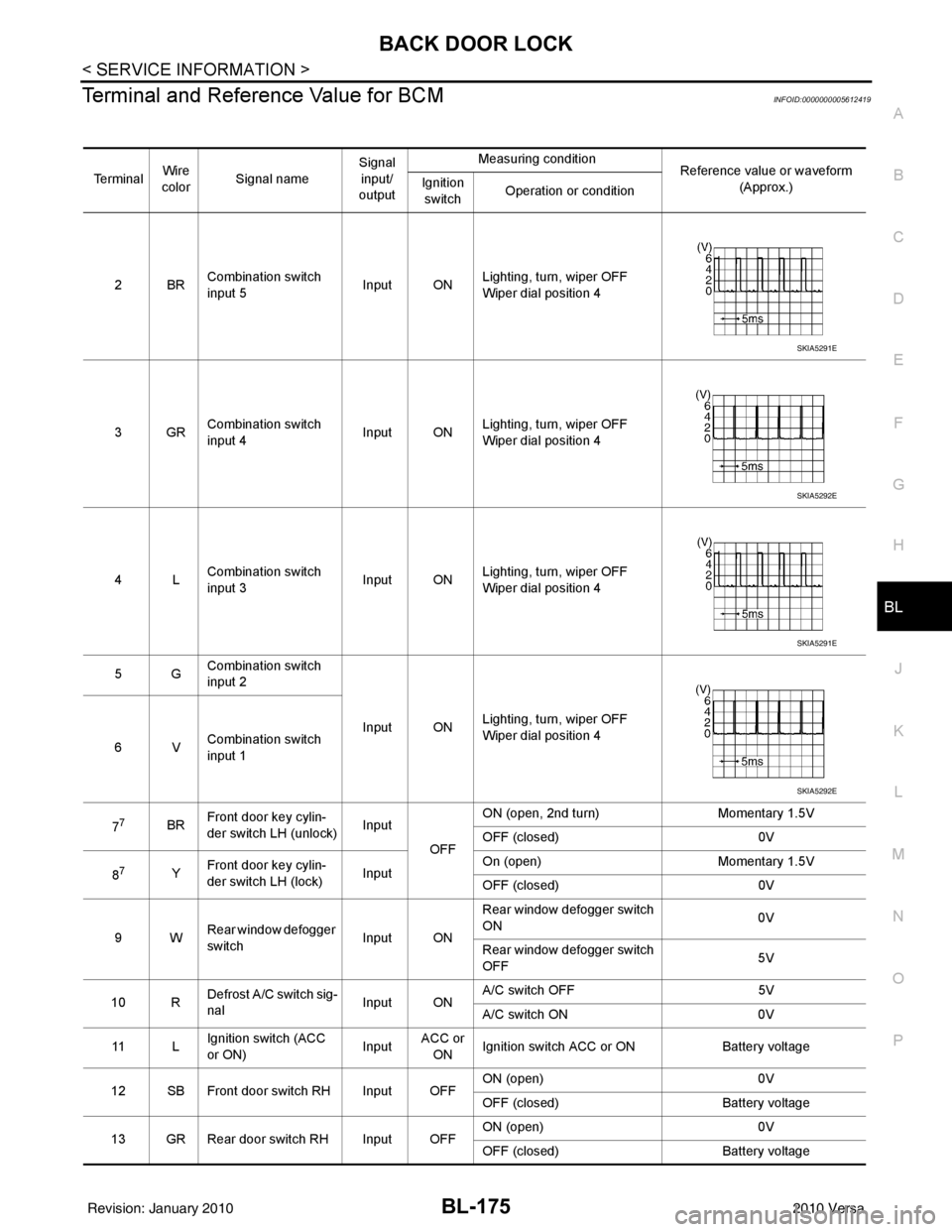
Terminal and Reference Value for BCMINFOID:0000000005612419
Te r m i n a l Wire
color Signal name Signal
input/
output Measuring condition
Reference value or waveform
(Approx.)
Ignition
switch Operation or condition
2BR Combination switch
input 5
Input ONLighting, turn, wiper OFF
Wiper dial position 4
3GR Combination switch
input 4 Input ONLighting, turn, wiper OFF
Wiper dial position 4
4L Combination switch
input 3
Input ONLighting, turn, wiper OFF
Wiper dial position 4
5G Combination switch
input 2
Input ONLighting, turn, wiper OFF
Wiper dial position 4
6V Combination switch
input 1
7
7BR Front door key cylin-
der switch LH (unlock) Input
OFFON (open, 2nd turn)
Momentary 1.5V
OFF (closed) 0V
8
7Y Front door key cylin-
der switch LH (lock) InputOn (open)
Momentary 1.5V
OFF (closed) 0V
9W Rear window defogger
switch Input ONRear window defogger switch
ON
0V
Rear window defogger switch
OFF 5V
10 R Defrost A/C switch sig-
nal
Input ONA/C switch OFF
5V
A/C switch ON 0V
11 L Ignition switch (ACC
or ON) InputACC or
ON Ignition switch ACC or ON
Battery voltage
12 SB Front door switch RH Input OFF ON (open)
0V
OFF (closed) Battery voltage
13 GR Rear door switch RH Input OFF ON (open)
0V
OFF (closed) Battery voltage
SKIA5291E
SKIA5292E
SKIA5291E
SKIA5292E
Revision: January 20102010 Versa