2010 NISSAN LATIO display
[x] Cancel search: displayPage 769 of 3745

BL-260
< SERVICE INFORMATION >
NATS (NISSAN ANTI-THEFT SYSTEM)
Self-diagnosis related item
• *: When NATS detects trouble, the security indicator lights up while ignition key is in the “ON” position.
SYMPTOM MATRIX CHART 2
Non self-diagnosis related item
*: CONSULT-III self-diagnostic results display screen “no malfunction is detected”.
Diagnosis Procedure 1INFOID:0000000005396711
Self-diagnostic results:
“CHAIN OF ECM-IMMU” displayed on CONSULT-III screen
First perform the “SELF-DIAG RESU LTS” in “BCM” with CONSULT-III, then perform the trouble diag-
nosis of malfunction system indicated “SELF-DIAG RESULTS” of “BCM”. Refer to BCS-18, "
CAN Com-
munication Inspection Using CONSULT-III (Self-Diagnosis)" .
SYMPTOMDisplayed “SELF-DIAG
RESULTS” on CON- SULT-III screen. DIAGNOSTIC PROCE-
DURE
(Reference page) SYSTEM
(Malfunctioning part or mode)
• Security indicator lighting up*
• Engine cannot be started CHAIN OF ECM-IMMU
[P1612] PROCEDURE 1
(BL-260
) In rare case, “CHAIN OF ECM-IMMU” might be stored
during key registration procedure, even if the system is
not malfunctioning.
Open circuit in battery voltage line of BCM circuit
Open circuit in ignition line of BCM circuit
Open circuit in ground line of BCM circuit
Open or short circuit between BCM and ECM commu-
nication line
ECM
BCM
DIFFERENCE OF KEY [P1615] PROCEDURE 6
(BL-266
) Unregistered ignition key is used.
BCM is malfunctioning.
CHAIN OF IMMU-KEY [P1614] PROCEDURE 2
(BL-262
) Malfunction of key ID chip
Communication line between ANT/ AMP and BCM:
Open circuit or short circuit of battery voltage line or
ground line
Open circuit in power source line of ANT/ AMP circuit
Open circuit in ground line of ANT/ AMP circuit
NATS antenna amp.
BCM
ID DISCORD, IMM- ECM
[P1611] PROCEDURE 3
(BL-263
) System initialization has not yet been completed.
ECM
LOCK MODE [P1610] PROCEDURE 5
(BL-265
) When the starting operation is carried out five or more
times consecutively under the following conditions,
NATS will shift the mode to one which prevents the en-
gine from being started.
• Unregistered ignition key is used.
• BCM or ECM’s malfunctioning.
Security indicator
lighting up* DON'T ERASE BE-
FORE CHECKING ENG DIAG WORK FLOW
(BL-257
) Engine trouble data and NATS trouble data have been
detected in ECM
SYMPTOM
DIAGNOSTIC PROCEDURE
(Reference page) SYSTEM
(Malfunctioning part or mode)
Security indicator does not light up*. PROCEDURE 4
(BL-264
) Security indictor.
Open circuit between Fuse and BCM
BCM
Revision: January 20102010 Versa
Page 770 of 3745
NATS (NISSAN ANTI-THEFT SYSTEM)BL-261
< SERVICE INFORMATION >
C
DE
F
G H
J
K L
M A
B
BL
N
O P
1.CONFIRM SELF-DIAGNOSTIC RESULTS
Confirm SELF-DIAGNOSTIC RESULTS “CHAIN OF ECM-IMMU” displayed on CONSULT-III screen.
NOTE:
In rare case, “CHAIN OF ECM-IMMU” might be stored during key registration procedure, even if the system is
not malfunctioning.
Is
“CHAIN OF ECM-IMMU” displayed?
Yes >> GO TO 2
No >> GO TO BL-259, "
Trouble Diagnosis" .
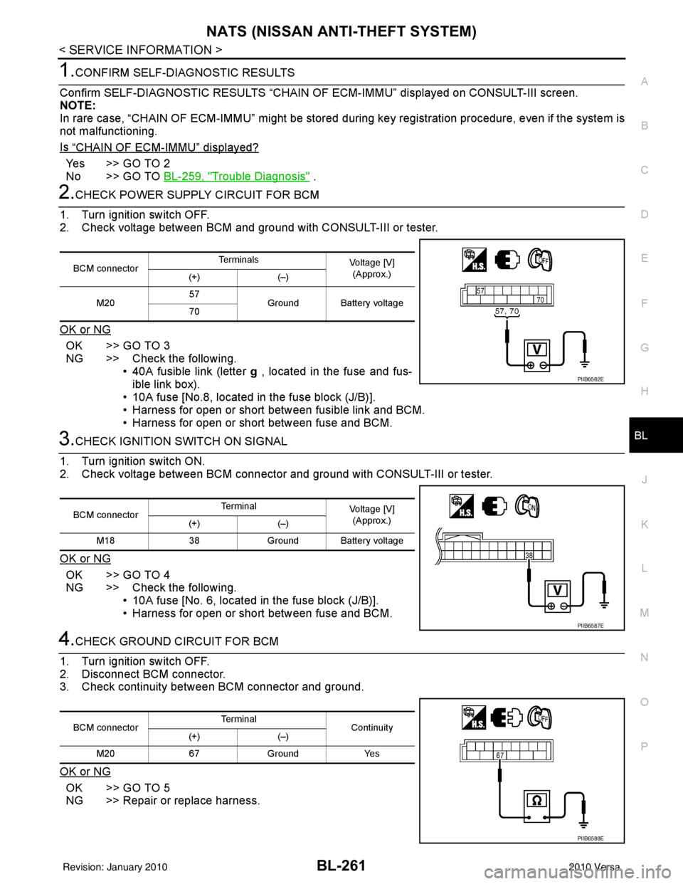
2.CHECK POWER SUPPLY CIRCUIT FOR BCM
1. Turn ignition switch OFF.
2. Check voltage between BCM and ground with CONSULT-III or tester.
OK or NG
OK >> GO TO 3
NG >> Check the following. • 40A fusible link (letter g , located in the fuse and fus-
ible link box).
• 10A fuse [No.8, located in the fuse block (J/B)].
• Harness for open or short between fusible link and BCM.
• Harness for open or short between fuse and BCM.
3.CHECK IGNITION SWITCH ON SIGNAL
1. Turn ignition switch ON.
2. Check voltage between BCM connector and ground with CONSULT-III or tester.
OK or NG
OK >> GO TO 4
NG >> Check the following. • 10A fuse [No. 6, located in the fuse block (J/B)].
• Harness for open or short between fuse and BCM.
4.CHECK GROUND CIRCUIT FOR BCM
1. Turn ignition switch OFF.
2. Disconnect BCM connector.
3. Check continuity between BCM connector and ground.
OK or NG
OK >> GO TO 5
NG >> Repair or replace harness.
BCM connector Te r m i n a l s
Voltage [V]
(Approx.)
(+) (–)
M20 57
Ground Battery voltage
70
PIIB6582E
BCM connector Terminal
Voltage [V]
(Approx.)
(+) (–)
M18 38Ground Battery voltage
PIIB6587E
BCM connector Terminal
Continuity
(+) (–)
M20 67 Ground Yes
PIIB6588E
Revision: January 20102010 Versa
Page 771 of 3745
BL-262
< SERVICE INFORMATION >
NATS (NISSAN ANTI-THEFT SYSTEM)
5.REPLACE BCM
1. Replace BCM. Refer to BCS-19, "
Removal and Installation of BCM".
2. Perform initialization with CONSULT-III.
For initialization, refer to “CONSULT-III Operation Manual NATS”.
Does the engine start?
Yes >> BCM is malfunctioning. • Replace BCM. Refer to BCS-19, "
Removal and Installation of BCM" .
• Perform initialization with CONSULT-III
• For initialization, refer to “CONSULT-III Operation Manual NATS”
No >> ECM is malfunctioning. • Replace ECM.
• Perform initialization or re-communicating function
• For initialization, refer to “CONSULT-III Operation Manual NATS”
• For re-communicating function, refer to BL-249, "
ECM Re-communicating Function"
Diagnosis Procedure 2INFOID:0000000005396712
Self-diagnostic results:
“CHAIN OF IMMU-KEY” displayed on CONSULT-III screen
1.CONFIRM SELF-DIAGNOSTIC RESULTS
Confirm SELF-DIAGNOSTIC RESULTS “CHAIN OF IMMU-KEY” displayed on CONSULT-III screen.
Is
“CHAIN OF IMMU-KEY” displayed?
Ye s > > G O T O 2
No >> GO TO BL-259, "
Trouble Diagnosis" .
2.CHECK NATS ANTENNA AMP. INSTALLATION
Check NATS antenna amp. installation. Refer to BL-266, "
How to Replace NATS Antenna Amp" .
OK or NG
OK >> GO TO 3
NG >> Reinstall NATS antenna amp. correctly.
3.CHECK NATS IGNITION KEY ID CHIP
Start engine with another registered NATS ignition key.
Does the engine start?
Yes >> Ignition key ID chip is malfunctioning. • Replace the ignition key
• Perform initialization with CONSULT-IIIFor initialization, refer to “CONSULT-III Operation Manual NATS”
No >> GO TO 4
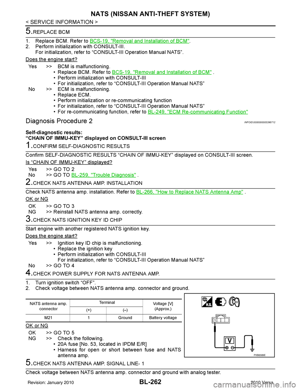
4.CHECK POWER SUPPLY FO R NATS ANTENNA AMP.
1. Turn ignition switch “OFF”.
2. Check voltage between NATS antenna amp. connector and ground.
OK or NG
OK >> GO TO 5
NG >> Check the following. • 20A fuse [No. 53, located in IPDM E/R]
• Harness for open or short between fuse and NATSantenna amp.
5.CHECK NATS ANTENNA AMP. SIGNAL LINE- 1
Check voltage between NATS antenna amp. connector and ground with analog tester.
NATS antenna amp. connector Te r m i n a l
Voltage [V]
(Approx.)
(+) (–)
M21 1Ground Battery voltage
PIIB6589E
Revision: January 20102010 Versa
Page 772 of 3745
NATS (NISSAN ANTI-THEFT SYSTEM)BL-263
< SERVICE INFORMATION >
C
DE
F
G H
J
K L
M A
B
BL
N
O P
OK or NG
OK >> GO TO 6
NG >> • Check harness for open or short between NATS antenna amp. and BCM. NOTE:
If harness is OK, replace BCM, perform initialization with CONSULT-III. For initialization, refer to
“CONSULT-III Operation Manual NATS”.
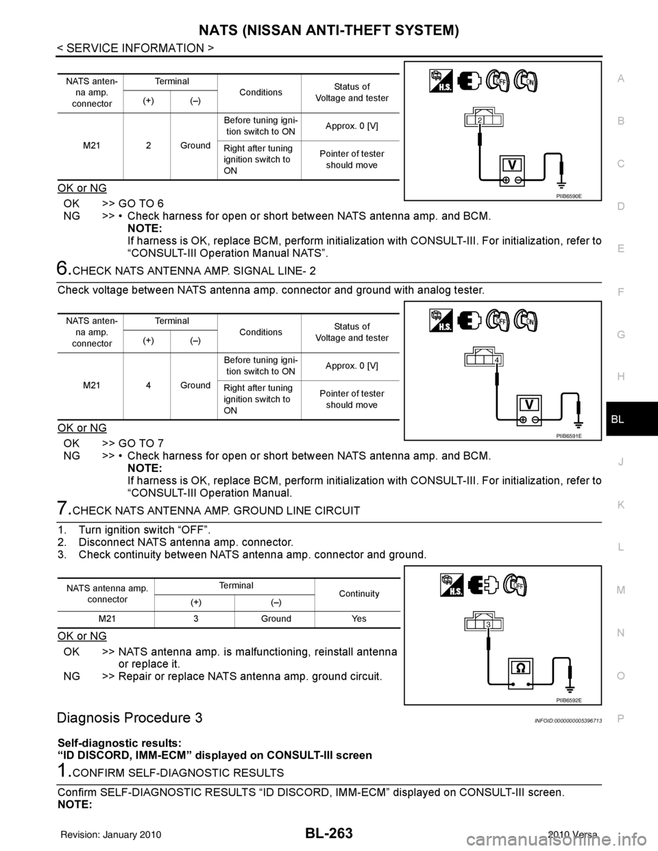
6.CHECK NATS ANTENNA AMP. SIGNAL LINE- 2
Check voltage between NATS antenna amp. connector and ground with analog tester.
OK or NG
OK >> GO TO 7
NG >> • Check harness for open or short between NATS antenna amp. and BCM. NOTE:
If harness is OK, replace BCM, perform initialization with CONSULT-III. For initialization, refer to
“CONSULT-III Operation Manual.
7.CHECK NATS ANTENNA AMP. GROUND LINE CIRCUIT
1. Turn ignition switch “OFF”.
2. Disconnect NATS antenna amp. connector.
3. Check continuity between NATS antenna amp. connector and ground.
OK or NG
OK >> NATS antenna amp. is malfunctioning, reinstall antenna or replace it.
NG >> Repair or replace NATS antenna amp. ground circuit.
Diagnosis Procedure 3INFOID:0000000005396713
Self-diagnostic results:
“ID DISCORD, IMM-ECM” disp layed on CONSULT-III screen
1.CONFIRM SELF-DIAGNOSTIC RESULTS
Confirm SELF-DIAGNOSTIC RESULTS “ID DISCO RD, IMM-ECM” displayed on CONSULT-III screen.
NOTE:
NATS anten-
na amp.
connector Te r m i n a l
Conditions Status of
Voltage and tester
(+) (–)
M21 2 Ground Before tuning igni-
tion switch to ON Approx. 0 [V]
Right after tuning
ignition switch to
ON Pointer of tester
should move
PIIB6590E
NATS anten- na amp.
connector Te r m i n a l
Conditions Status of
Voltage and tester
(+) (–)
M21 4 Ground Before tuning igni-
tion switch to ON Approx. 0 [V]
Right after tuning
ignition switch to
ON Pointer of tester
should move
PIIB6591E
NATS antenna amp.
connector Te r m i n a l
Continuity
(+) (–)
M21 3Ground Yes
PIIB6592E
Revision: January 20102010 Versa
Page 773 of 3745
BL-264
< SERVICE INFORMATION >
NATS (NISSAN ANTI-THEFT SYSTEM)
“ID DISCORD IMM-ECM”:
Registered ID of BCM is in discord with that of ECM.
Is
“ID DISCORD IMM-ECM” displayed?
Ye s > > G O T O 2
No >> GO TO BL-259, "
Trouble Diagnosis" .
2.PERFORM INITIALIZATION WITH CONSULT-III
Perform initialization with CONSULT-III. Re-register all NATS ignition key IDs.
For initialization, refer to “CONSULT-III Operation Manual NATS”.
NOTE:
If the initialization is not completed or ma lfunctions, CONSULT-III shows message on the screen.
Can the system be initialized?
Yes >> • Start engine. (END) • (System initialization had not been completed.)
No >> ECM is malfunctioning. • Replace ECM.
• Perform initialization with CONSULT-III
For initialization, refer to “CONSULT-III Operation Manual NATS”
Diagnosis Procedure 4INFOID:0000000005396714
“COMBINATION METER (SECURITY) DOES NOT LIGHT UP”
1.CHECK FUSE
Check 10A fuse [No.13, located in the fuse block (J/B)]
OK or NG
OK >> GO TO 2
NG >> Replace fuse.
2.CHECK COMBINATION METER (SECURITY)
1. Install 10A fuse.
2. Start engine and turn ignition switch OFF.
3. Check if the combination meter (security) lights up.
OK or NG
OK >> Inspection End.
NG >> GO TO 3
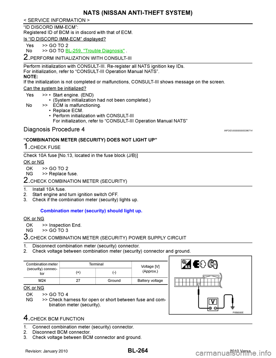
3.CHECK COMBINATION METER (SECURITY) POWER SUPPLY CIRCUIT
1. Disconnect combination meter (security) connector.
2. Check voltage between combination meter (security) connector and ground.
OK or NG
OK >> GO TO 4
NG >> Check harness for open or short between fuse and com- bination meter (security).
4.CHECK BCM FUNCTION
1. Connect combination meter (security) connector.
2. Disconnect BCM connector.
3. Check voltage between BCM connector and ground. Combination meter (security) should light up.
Combination meter
(security) connec-
tor Te r m i n a l
Voltage [V]
(Approx.)
(+) (-)
M24 27Ground Battery voltage
PIIB6593E
Revision: January 20102010 Versa
Page 774 of 3745
NATS (NISSAN ANTI-THEFT SYSTEM)BL-265
< SERVICE INFORMATION >
C
DE
F
G H
J
K L
M A
B
BL
N
O P
OK or NG
OK >> BCM is malfunctioning. • Replace BCM. Refer to BCS-19, "
Removal and Instal-
lation of BCM" .
• Perform initialization with CONSULT-III
• For initialization, refer to “CONSULT-III Operation Manual.
NG >> Check the following. • Harness for open or short between combination meter (security) and BCM
• Indicator lamp condition
Diagnosis Procedure 5INFOID:0000000005396715
Self-diagnostic results:
“LOCK MODE” displayed on CONSULT-III screen
1.CONFIRM SELF-DIAGNOSTIC RESULTS
Confirm SELF-DIAGNOSTIC RESULTS “LOCK MODE” is displayed on CONSULT-III screen.
Is
“LOCK MODE” displayed?
Yes >> GO TO 2
No >> GO TO BL-259, "
Trouble Diagnosis" .
2.ESCAPE FROM LOCK MODE
1. Turn ignition switch OFF.
2. Turn ignition switch ON with registered key. (Do not start engine.) Wait 5 seconds.
3. Return the key to OFF position. Wait 5 seconds.
4. Repeat steps 2 and 3 twice (total of three cycles).
5. Start the engine.
Does engine start?
Yes >> System is OK (Now system is escaped from “LOCK MODE”).
No >> GO TO 3
3.PERFORM INITIALIZATION WITH CONSULT-III
Perform initialization with CONSULT-III.
For initialization, refer to “CONSULT-III Operation Manual.
NOTE:
If the initialization is not completed or malf unctions, CONSULT-III shows the message on the screen.
Can the system be initialized?
Yes >> System is OK.
No >> GO TO 4
4.PERFORM INITIALIZATION WITH CONSULT-III AGAIN
1. Replace BCM.
2. Perform initialization with CONSULT-III. For initialization, refer to “CON SULT-III Operation Manual NATS”.
NOTE:
If the initialization is not completed or malf unctions, CONSULT-III shows the message on the screen.
Can the system be initialized?
Yes >> System is OK. (BCM is malfunctioning.)
No >> ECM is malfunctioning. • Replace ECM.
• Perform initialization with CONSULT-III
• For initialization, refer to “CONSULT-III Operation Manual NATS”
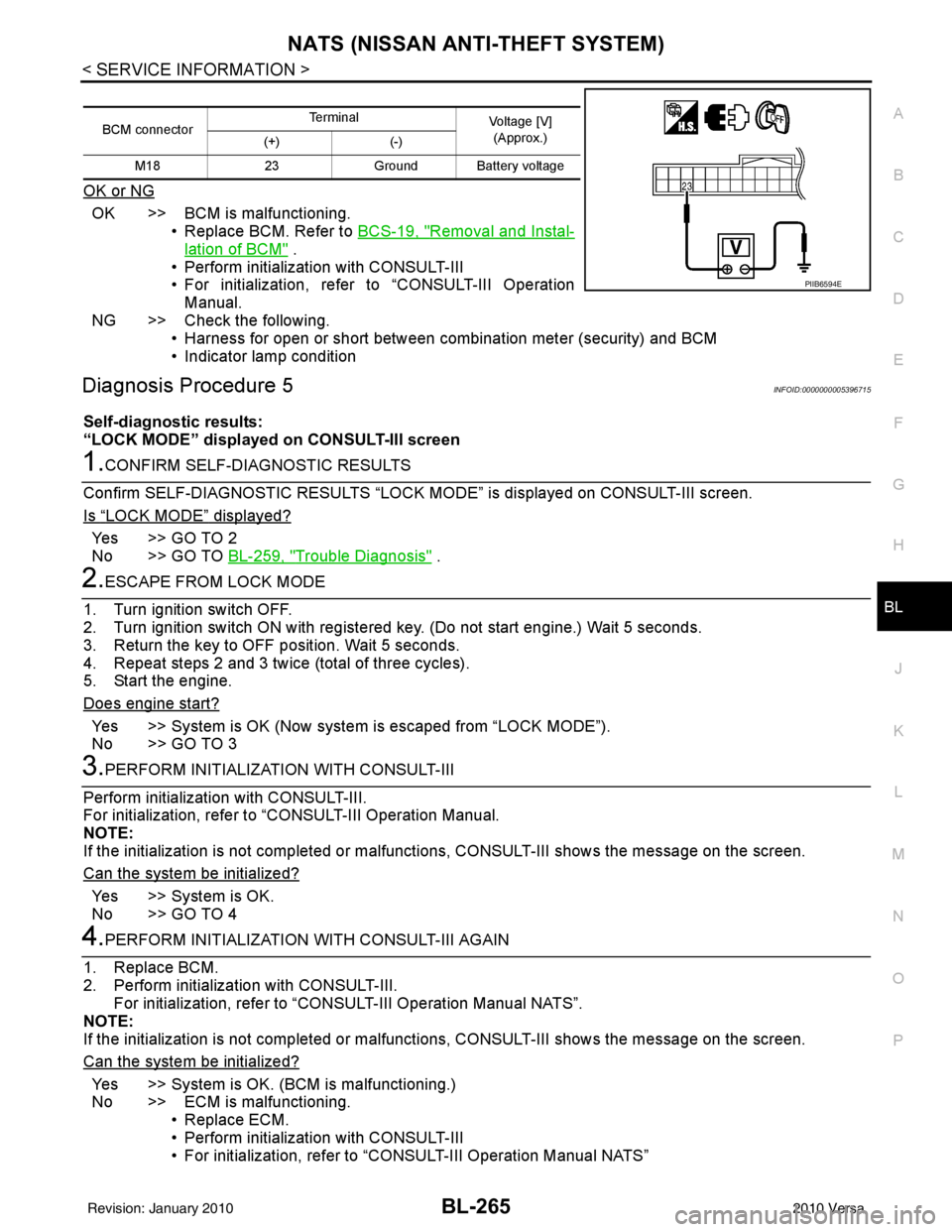
BCM connector Terminal
Voltage [V]
(Approx.)
(+) (-)
M18 23Ground Battery voltage
PIIB6594E
Revision: January 20102010 Versa
Page 775 of 3745
BL-266
< SERVICE INFORMATION >
NATS (NISSAN ANTI-THEFT SYSTEM)
Diagnosis Procedure 6
INFOID:0000000005396716
Self-diagnostic results:
“DIFFERENCE OF KEY” disp layed on CONSULT-III screen
1.CONFIRM SELF-DIAGNOSTIC RESULTS
Confirm SELF-DIAGNOSTIC RESU LTS “DIFFERENCE OF KEY” displayed on CONSULT-III screen.
Is
“DIFFERENCE OF KEY” displayed?
YES >> GO TO 2
NO >> GO TO BL-259, "
Trouble Diagnosis".
2.PERFORM INITIALIZATION WITH CONSULT-III
Perform initialization with CONSULT-III. Re-register all NATS ignition key IDs.
For initialization and registration of NATS ignition key IDs, refer to CONSULT-III Operation Manual.
NOTE:
If the initialization is not completed or ma lfunctions, CONSULT-III shows message on the screen.
Can the system be initialized and can the engine be started with re-registered NATS ignition key?
YES >> • Ignition key ID was unregistered.
NO >> • BCM is malfunctioning. • Replace BCM. Refer to BCS-19, "
Removal and Installation of BCM".
• Perform initialization with CONSULT-III.
• For initialization, refer to CONSULT-III Operation Manual.
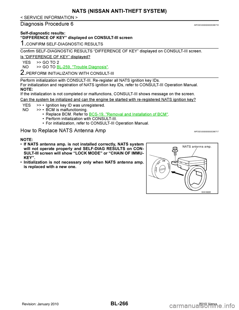
How to Replace NATS Antenna AmpINFOID:0000000005396717
NOTE:
• If NATS antenna amp. is not installed correctly, NATS system
will not operate properly and SELF-DIAG RESULTS on CON-
SULT-III screen will show “LOCK MODE” or “CHAIN OF IMMU-
KEY”.
• Initialization is not necessary only when NATS antenna amp.
is replaced with a new one.
SIIA1683E
Revision: January 20102010 Versa
Page 909 of 3745
![NISSAN LATIO 2010 Service Repair Manual TROUBLE DIAGNOSISBRC-19
< SERVICE INFORMATION > [ABS]
C
D
E
G H
I
J
K L
M A
B
BRC
N
O P
• If ABS actuator and electric unit (control unit) connec tion is loose, tighten the piping to the specified
t NISSAN LATIO 2010 Service Repair Manual TROUBLE DIAGNOSISBRC-19
< SERVICE INFORMATION > [ABS]
C
D
E
G H
I
J
K L
M A
B
BRC
N
O P
• If ABS actuator and electric unit (control unit) connec tion is loose, tighten the piping to the specified
t](/manual-img/5/57358/w960_57358-908.png)
TROUBLE DIAGNOSISBRC-19
< SERVICE INFORMATION > [ABS]
C
D
E
G H
I
J
K L
M A
B
BRC
N
O P
• If ABS actuator and electric unit (control unit) connec tion is loose, tighten the piping to the specified
torque and recheck for leaks.
• If there is damage to the connection flare nut or ABS actuator and electric unit (control unit) threads,
replace the damaged part and recheck for leaks.
• When there is fluid leaking or seeping from a fluid connection, use a clean cloth to wipe off the fluid and recheck for leaks. If fluid is still seeping out, replace the damaged part. If the fluid is leaking at the ABS
actuator and electric unit (control unit), replace the ABS actuator and electric unit (control unit) assem-
bly.
CAUTION:
The ABS actuator and electric unit (control unit) cannot be disassembl\
ed and must be replaced
as an assembly.
3. Check the brake pads for excessive wear.
POWER SYSTEM TERMINAL LOOSENESS AND BATTERY INSPECTION
Make sure the battery positive cable, negative cabl e and ground connection are not loose. In addition, make
sure the battery is sufficiently charged.
ABS WARNING LAMP INSPECTION
1. Make sure ABS warning lamp turns on for approximately 2 seconds when the ignition switch is turned ON. If it does not, check CAN communications. If ther e are no errors with the CAN communication system,
replace the combination meter. Refer to IP-12, "
Removal and Installation".
2. Make sure the lamp turns off approximately 2 seconds after the ignition switch is turned ON. If the lamp does not turn off, conduct self-diagnosis of ABS actuator and electric unit (control unit). If no malfunctions
are detected in self-diagnosis, replace combination meter. Refer to IP-12, "
Removal and Installation".
3. After conducting the self-diagnosis, be sure to erase the error memory. Refer to BRC-20, "
CONSULT-III
Function (ABS)".
Warning Lamp and Indicator TimingINFOID:0000000005397037
Note 1: Brake warning lamp will turn on when the parking brake is applied or when the brake fluid level is low.
x: ON
–: OFF
Control Unit Input/Out put Signal StandardINFOID:0000000005397038
REFERENCE VALUE FROM CONSULT-III
CAUTION:
The display shows the control unit calculation data, so a normal value might be displayed even in the
event the output circuit (harness) is open or short circuited.
Condition ABS
warning lamp BRAKE
warning lamp [Note 1] Remarks
When the ignition switch is OFF –– –
After the ignition switch is turned ON for approx. 1
second ××
–
After the ignition switch is turned ON for approx. 2
seconds ––Lamp goes off approx. 2 seconds after the
engine is started.
ABS malfunction ×––
EBD malfunction ××–
Revision: January 20102010 Versa