2010 NISSAN CUBE reset
[x] Cancel search: resetPage 15 of 329
Black plate (11,1)
Model "Z12-D" EDITED: 2009/ 9/ 17
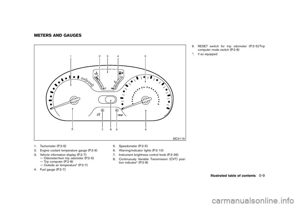
SIC4119
1. Tachometer (P.2-6)
2. Engine coolant temperature gauge (P.2-6)
3. Vehicle information display (P.2-7)— Odometer/twin trip odometer (P.2-5)
— Trip computer (P.2-8)
— Outside air temperature* (P.2-7)
4. Fuel gauge (P.2-7) 5. Speedometer (P.2-5)
6. Warning/indicator lights (P.2-10)
7. Instrument brightness control knob (P.2-26)
8. Continuously Variable Transmission (CVT) posi-
tion indicator* (P.2-8) 9. RESET switch for trip odometer (P.2-5)/Trip
computer mode switch (P.2-8)
*: if so equippedMETERS AND GAUGES
Illustrated table of contents
0-9
Page 75 of 329
Black plate (7,1)
2 Instruments and controls
Model "Z12-D" EDITED: 2009/ 9/ 17
Cockpit............................................................ 2-2
Instrument panel ................................................ 2-3
Meters and gauges ............................................. 2-4
Speedometer and odometer ............................. 2-5
Tachometer ................................................... 2-6
Engine coolant temperature gauge ..................... 2-6
Fuel gauge ................................................... 2-7
Vehicle information display ................................ 2-7
Outside air temperature (if so equipped) .............. 2-7
Continuously Variable Transmission (CVT)
position indicator (if so equipped) ...................... 2-8
Trip computer ................................................ 2-8
Warning/indicator lights and audible reminders ....... 2-10
Checking bulbs ........................................... 2-10
Warning lights ............................................. 2-10
Indicator lights ............................................. 2-15
Audible reminders ........................................ 2-17
Security systems .............................................. 2-17
Vehicle Security System. ................................ 2-17
NISSAN Vehicle Immobilizer System ................. 2-19
Windshield wiper and washer switch .................... 2-20
Rear window wiper and washer switch .................. 2-22
Rear window and outside mirror defroster switch ..... 2-23Headlight and turn signal switch
.......................... 2-23
Headlight switch .......................................... 2-23
Turn signal switch ........................................ 2-26
Fog light switch (if so equipped) ...................... 2-27
Hazard warning flasher switch ............................. 2-27
Horn ............................................................. 2-28
Vehicle Dynamic Control (VDC) OFF switch ........... 2-28
Clock (if so equipped) ....................................... 2-28
Adjusting the time ........................................ 2-29
Resetting the time (Type B) ............................ 2-30
Power outlet ................................................... 2-31
Storage ......................................................... 2-31
Cup holders ................................................ 2-31
Glove box .................................................. 2-33
Rear pillar pocket ......................................... 2-34
Luggage hooks ............................................ 2-34
Utility hooks (if so equipped) ........................... 2-35
Windows ....................................................... 2-36
Power windows ........................................... 2-36
Interior lights ................................................... 2-38
Map lights (if so equipped) ............................. 2-38
Map light control switch (if so equipped) ........... 2-39
Ceiling light ................................................ 2-39
Cargo light (if so equipped) ................................ 2-40
Page 78 of 329
Black plate (78,1)
Model "Z12-D" EDITED: 2009/ 9/ 17
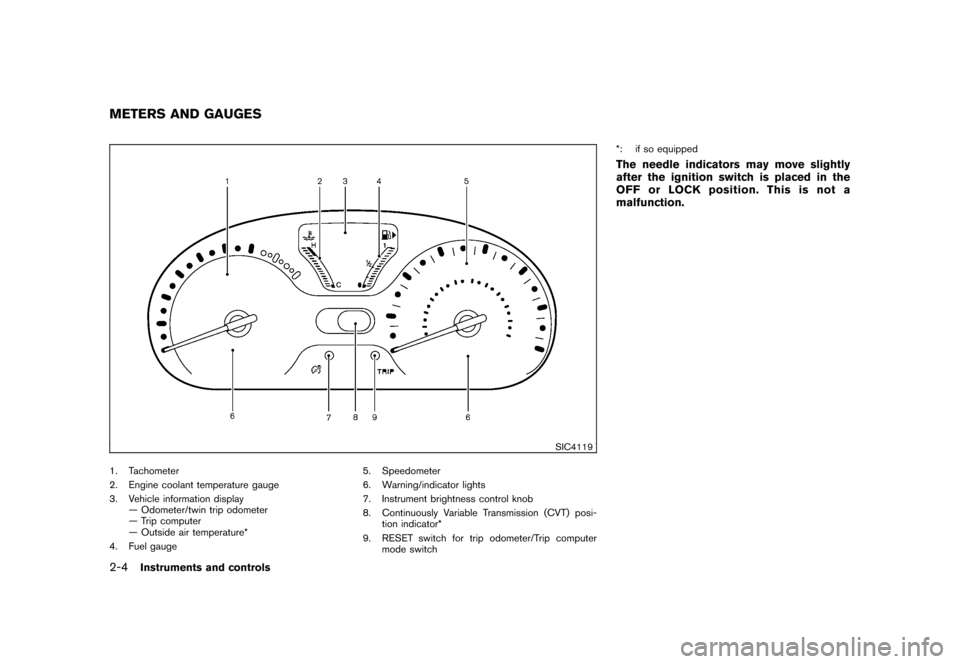
SIC4119
1. Tachometer
2. Engine coolant temperature gauge
3. Vehicle information display— Odometer/twin trip odometer
— Trip computer
— Outside air temperature*
4. Fuel gauge 5. Speedometer
6. Warning/indicator lights
7. Instrument brightness control knob
8. Continuously Variable Transmission (CVT) posi-
tion indicator*
9. RESET switch for trip odometer/Trip computer mode switch *: if so equipped
The needle indicators may move slightly
after the ignition switch is placed in the
OFF or LOCK position. This is not a
malfunction.
METERS AND GAUGES2-4
Instruments and controls
Page 79 of 329
Black plate (79,1)
Model "Z12-D" EDITED: 2009/ 9/ 17
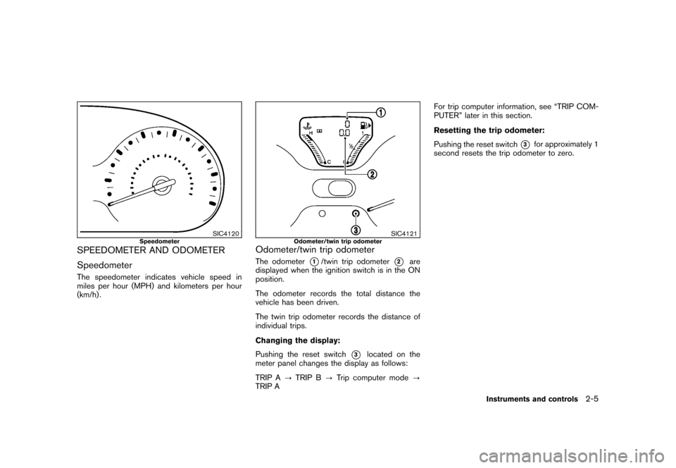
SIC4120
Speedometer
SPEEDOMETER AND ODOMETER
SpeedometerThe speedometer indicates vehicle speed in
miles per hour (MPH) and kilometers per hour
(km/h) .
SIC4121
Odometer/twin trip odometer
Odometer/twin trip odometerThe odometer
*1/twin trip odometer
*2
are
displayed when the ignition switch is in the ON
position.
The odometer records the total distance the
vehicle has been driven.
The twin trip odometer records the distance of
individual trips.
Changing the display:
Pushing the reset switch
*3
located on the
meter panel changes the display as follows:
TRIP A ?TRIP B ?Trip computer mode ?
TRIP A For trip computer information, see “TRIP COM-
PUTER” later in this section.
Resetting the trip odometer:
Pushing the reset switch
*3
for approximately 1
second resets the trip odometer to zero.
Instruments and controls
2-5
Page 83 of 329
Black plate (83,1)
Model "Z12-D" EDITED: 2009/ 9/ 17
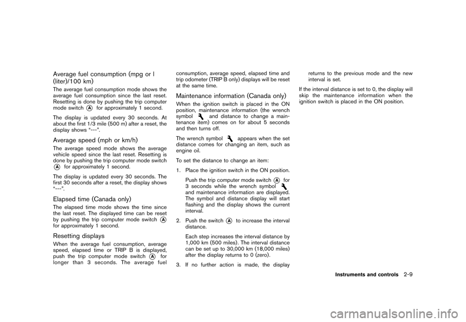
Average fuel consumption (mpg or l
(liter)/100 km)The average fuel consumption mode shows the
average fuel consumption since the last reset.
Resetting is done by pushing the trip computer
mode switch
*A
for approximately 1 second.
The display is updated every 30 seconds. At
about the first 1/3 mile (500 m) after a reset, the
display shows “---”.
Average speed (mph or km/h)The average speed mode shows the average
vehicle speed since the last reset. Resetting is
done by pushing the trip computer mode switch*A
for approximately 1 second.
The display is updated every 30 seconds. The
first 30 seconds after a reset, the display shows
“---”.
Elapsed time (Canada only)The elapsed time mode shows the time since
the last reset. The displayed time can be reset
by pushing the trip computer mode switch
*A
for approximately 1 second.Resetting displaysWhen the average fuel consumption, average
speed, elapsed time or TRIP B is displayed,
push the trip computer mode switch
*A
for
longer than 3 seconds. The average fuel consumption, average speed, elapsed time and
trip odometer (TRIP B only) displays will be reset
at the same time.
Maintenance information (Canada only)When the ignition switch is placed in the ON
position, maintenance information (the wrench
symbol
and distance to change a main-
tenance item) comes on for about 5 seconds
and then turns off.
The wrench symbol
appears when the set
distance comes for changing an item, such as
engine oil.
To set the distance to change an item:
1. Place the ignition switch in the ON position.
Push the trip computer mode switch
*A
for
3 seconds while the wrench symbol
and maintenance information are displayed.
The symbol and distance display will start
flashing and the display shows the current
interval.
2. Push the switch
*A
to increase the interval
distance.
Each step increases the interval distance by
1,000 km (500 miles) . The interval distance
can be set up to 30,000 km (18,000 miles)
after the display returns to 0 (zero) .
3. If no further action is made, the display returns to the previous mode and the new
interval is set.
If the interval distance is set to 0, the display will
skip the maintenance information when the
ignition switch is placed in the ON position.
Instruments and controls
2-9
Page 87 of 329
Black plate (87,1)
Model "Z12-D" EDITED: 2009/ 9/ 17
Low tire pressure warning light
Your vehicle is equipped with a Tire Pressure
Monitoring System (TPMS) that monitors the tire
pressure of all tires except the spare.
The low tire pressure warning light warns of low
tire pressure or indicates that the TPMS is not
functioning properly.
After the ignition switch is placed in the ON
position, this light illuminates for about 1 second
and turns off.
Low tire pressure warning:
If the vehicle is being driven with low tire
pressure, the warning light will illuminate.
When the low tire pressure warning light
illuminates, you should stop and adjust the tire
pressure to the recommended COLD tire
pressure shown on the Tire and Loading
Information label. The low tire pressure warning
light does not automatically turn off when the tire
pressure is adjusted. After the tire is inflated to
the recommended pressure, the vehicle must be
driven at speeds above 16 MPH (25 km/h) to
activate the TPMS and turn off the low tire
pressure warning light. Use a tire pressure
gauge to check the tire pressure.
For additional information, see “TIRE PRES-
SURE MONITORING SYSTEM (TPMS)” in the“5. Starting and driving” section and “TIRE
PRESSURE MONITORING SYSTEM (TPMS)”
in the “6. In case of emergency” section.
TPMS malfunction:
If the TPMS is not functioning properly, the low
tire pressure warning light will flash for approxi-
mately 1 minute when the ignition switch is
placed in the ON position. The light will remain
on after 1 minute. Have the system checked by a
NISSAN dealer.
For additional information, see “TIRE PRES-
SURE MONITORING SYSTEM (TPMS)” in the
“5. Starting and driving” section.
WARNING
.
If the light does not illuminate with
the ignition switch placed in the ON
position, have the vehicle checked
by a NISSAN dealer as soon as
possible.
. If the light illuminates while driving,
avoid sudden steering maneuvers or
abrupt braking, reduce vehicle
speed, pull off the road to a safe
location and stop the vehicle as
soon as possible. Driving with un-
der-inflated tires may permanently
damage the tires and increase the likelihood of tire failure. Serious
vehicle damage could occur and
may lead to an accident and could
result in serious personal injury.
Check the tire pressure for all four
tires. Adjust the tire pressure to the
recommended COLD tire pressure
shownontheTireandLoading
Information label to turn the low
tire pressure warning light OFF. If
the light still illuminates while driv-
ing after adjusting the tire pressure,
a tire may be flat. If you have a flat
tire, replace it with a spare tire as
soon as possible.
. When a spare tire is mounted or a
wheel is replaced, the TPMS will not
function and the low tire pressure
warning light will flash for approxi-
mately 1 minute. The light will
remain on after 1 minute. Contact
your NISSAN dealer as soon as
possible for tire replacement and/
or system resetting.
. Replacing tires with those not ori-
ginally specified by NISSAN could
affect the proper operation of the
TPMS.
Instruments and controls
2-13
Page 104 of 329
Black plate (104,1)
Model "Z12-D" EDITED: 2009/ 9/ 17
4. Push the MENU button
*1
again. The
display will switch to the minute adjustment
mode.
5. Push the TUNE or SEEK button to adjust the minutes.
6. Push the MENU button again to exit the clock mode.
The display will return to the regular clock
display after 5 seconds.
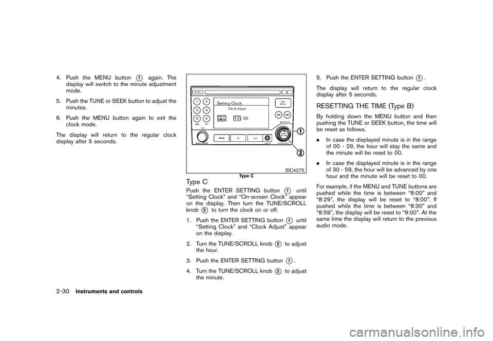
SIC4275
Type C
Type CPush the ENTER SETTING button
*1
until
“Setting Clock” and “On-screen Clock” appear
on the display. Then turn the TUNE/SCROLL
knob
*2
to turn the clock on or off.
1. Push the ENTER SETTING button
*1
until
“Setting Clock” and “Clock Adjust” appear
on the display.
2. Turn the TUNE/SCROLL knob
*2
to adjust
the hour.
3. Push the ENTER SETTING button*1.
4. Turn the TUNE/SCROLL knob
*2
to adjust
the minute. 5. Push the ENTER SETTING button
*1.
The display will return to the regular clock
display after 5 seconds.
RESETTING THE TIME (Type B)By holding down the MENU button and then
pushing the TUNE or SEEK button, the time will
be reset as follows.
. In case the displayed minute is in the range
of 00 - 29, the hour will stay the same and
the minute will be reset to 00.
. In case the displayed minute is in the range
of 30 - 59, the hour will be advanced by one
hour and the minute will be reset to 00.
For example, if the MENU and TUNE buttons are
pushed while the time is between “8:00” and
“8:29”, the display will be reset to “8:00”. If
pushed while the time is between “8:30” and
“8:59”, the display will be reset to “9:00”. At the
same time the display will return to the previous
audio mode.
2-30
Instruments and controls
Page 135 of 329
Black plate (137,1)
Model "Z12-D" EDITED: 2009/ 9/ 17
WARNING
.Make sure the hood is completely
closed and latched before driving.
Failure to do so could cause the
hood to fly open and result in an
accident.
. If you see steam or smoke coming
from the engine compartment, to
avoid injury do not open the hood.
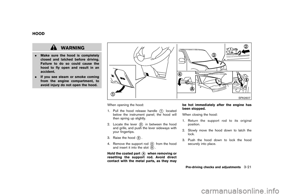
SPA2607
When opening the hood:
1. Pull the hood release handle
*1
located
below the instrument panel; the hood will
then spring up slightly.
2. Locate the lever
*2
in between the hood
and grille, and push the lever sideways with
your fingertips.
3. Raise the hood
*3.
4. Remove the support rod
*4
from the hood
and insert it into the slot
*5.
Hold the coated part
*A
when removing or
resetting the support rod. Avoid direct
contact with the metal parts, as they may be hot immediately after the engine has
been stopped.
When closing the hood:
1. Return the support rod to its original
position.
2. Slowly move the hood down to latch the lock.
3. Push the hood down to lock the hood securely into place.
HOOD
Pre-driving checks and adjustments
3-21