2010 NISSAN CUBE clock
[x] Cancel search: clockPage 14 of 329
Black plate (10,1)
Model "Z12-D" EDITED: 2009/ 9/ 17
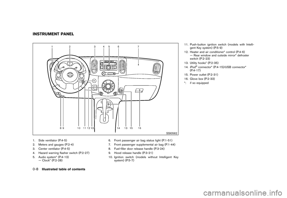
SSI0562
1. Side ventilator (P.4-5)
2. Meters and gauges (P.2-4)
3. Center ventilator (P.4-5)
4. Hazard warning flasher switch (P.2-27)
5. Audio system* (P.4-13)— Clock* (P.2-28) 6. Front passenger air bag status light (P.1-51)
7. Front passenger supplemental air bag (P.1-44)
8. Fuel-filler door release handle (P.3-24)
9. Hood release handle (P.3-21)
10. Ignition switch (models without Intelligent Key
system) (P.5-7) 11. Push-button ignition switch (models with Intelli-
gent Key system) (P.5-9)
12. Heater and air conditioner* control (P.4-6) — Rear window and outside mirror* defroster
switch (P.2-23)
13. Utility hooks* (P.2-35)
14. iPod
®connector* (P.4-15)/USB connector*
(P.4-17)
15. Power outlet (P.2-31)
16. Glove box (P.2-33)
*: if so equipped
INSTRUMENT PANEL0-8
Illustrated table of contents
Page 75 of 329
Black plate (7,1)
2 Instruments and controls
Model "Z12-D" EDITED: 2009/ 9/ 17
Cockpit............................................................ 2-2
Instrument panel ................................................ 2-3
Meters and gauges ............................................. 2-4
Speedometer and odometer ............................. 2-5
Tachometer ................................................... 2-6
Engine coolant temperature gauge ..................... 2-6
Fuel gauge ................................................... 2-7
Vehicle information display ................................ 2-7
Outside air temperature (if so equipped) .............. 2-7
Continuously Variable Transmission (CVT)
position indicator (if so equipped) ...................... 2-8
Trip computer ................................................ 2-8
Warning/indicator lights and audible reminders ....... 2-10
Checking bulbs ........................................... 2-10
Warning lights ............................................. 2-10
Indicator lights ............................................. 2-15
Audible reminders ........................................ 2-17
Security systems .............................................. 2-17
Vehicle Security System. ................................ 2-17
NISSAN Vehicle Immobilizer System ................. 2-19
Windshield wiper and washer switch .................... 2-20
Rear window wiper and washer switch .................. 2-22
Rear window and outside mirror defroster switch ..... 2-23Headlight and turn signal switch
.......................... 2-23
Headlight switch .......................................... 2-23
Turn signal switch ........................................ 2-26
Fog light switch (if so equipped) ...................... 2-27
Hazard warning flasher switch ............................. 2-27
Horn ............................................................. 2-28
Vehicle Dynamic Control (VDC) OFF switch ........... 2-28
Clock (if so equipped) ....................................... 2-28
Adjusting the time ........................................ 2-29
Resetting the time (Type B) ............................ 2-30
Power outlet ................................................... 2-31
Storage ......................................................... 2-31
Cup holders ................................................ 2-31
Glove box .................................................. 2-33
Rear pillar pocket ......................................... 2-34
Luggage hooks ............................................ 2-34
Utility hooks (if so equipped) ........................... 2-35
Windows ....................................................... 2-36
Power windows ........................................... 2-36
Interior lights ................................................... 2-38
Map lights (if so equipped) ............................. 2-38
Map light control switch (if so equipped) ........... 2-39
Ceiling light ................................................ 2-39
Cargo light (if so equipped) ................................ 2-40
Page 77 of 329
Black plate (77,1)
Model "Z12-D" EDITED: 2009/ 9/ 17
SSI0562
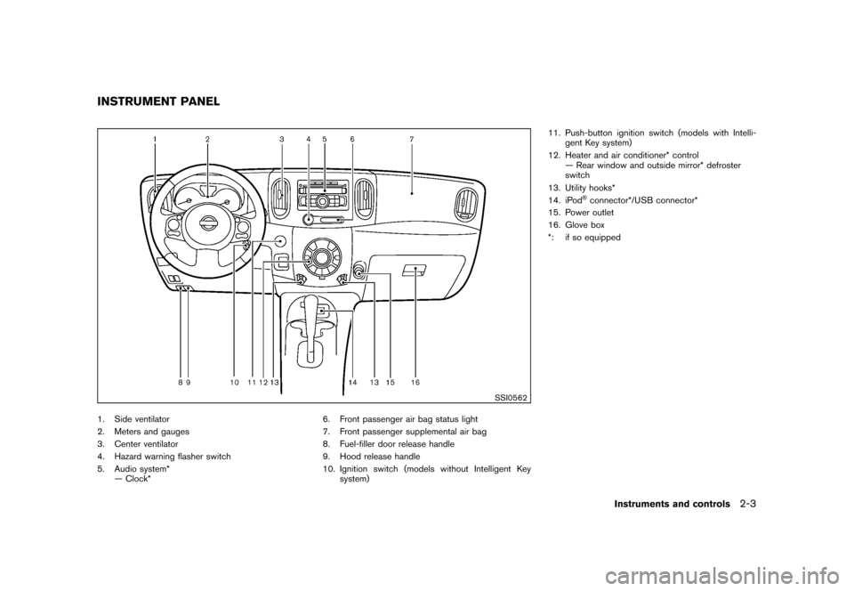
1. Side ventilator
2. Meters and gauges
3. Center ventilator
4. Hazard warning flasher switch
5. Audio system*— Clock* 6. Front passenger air bag status light
7. Front passenger supplemental air bag
8. Fuel-filler door release handle
9. Hood release handle
10. Ignition switch (models without Intelligent Key
system) 11. Push-button ignition switch (models with Intelli-
gent Key system)
12. Heater and air conditioner* control — Rear window and outside mirror* defroster
switch
13. Utility hooks*
14. iPod
®connector*/USB connector*
15. Power outlet
16. Glove box
*: if so equipped
INSTRUMENT PANEL
Instruments and controls
2-3
Page 96 of 329
Black plate (96,1)
Model "Z12-D" EDITED: 2009/ 9/ 17
WARNING
In freezing temperatures the washer
solution may freeze on the rear window
glass and obscure your vision. Warm
the rear window with the defroster
before you wash the rear window.
CAUTION
.Do not operate the washer continu-
ously for more than 30 seconds.
. Do not operate the washer if the
reservoir tank is empty.
. Do not fill the window washer
reservoir tank with washer fluid
concentrates at full strength. Some
methyl alcohol based washer fluid
concentrates may permanently stain
the grille if spilled while filling the
window washer reservoir tank.
. Pre-mix washer fluid concentrates
with water to the manufacturer’s
recommended levels before pouring
the fluid into the window washer
reservoir tank. Do not use the
window washer reservoir tank to
mix the washer fluid concentrate and water.
If the rear window wiper operation is
interrupted by snow or ice, the wiper may
stop moving to protect its motor. If this
occurs, turn the wiper switch to the OFF
position and remove the snow or ice that is
on and around the wiper arms. In approxi-
mately 1 minute, turn the switch on again
to operate the wiper.
SIC3666
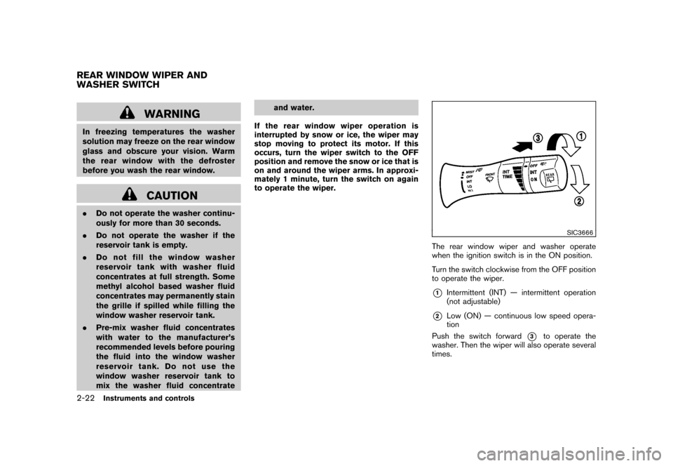
The rear window wiper and washer operate
when the ignition switch is in the ON position.
Turn the switch clockwise from the OFF position
to operate the wiper.*1
Intermittent (INT) — intermittent operation
(not adjustable)
*2
Low (ON) — continuous low speed opera-
tion
Push the switch forward
*3
to operate the
washer. Then the wiper will also operate several
times.
REAR WINDOW WIPER AND
WASHER SWITCH2-22
Instruments and controls
Page 102 of 329
Black plate (102,1)
Model "Z12-D" EDITED: 2009/ 9/ 17
SIC4130
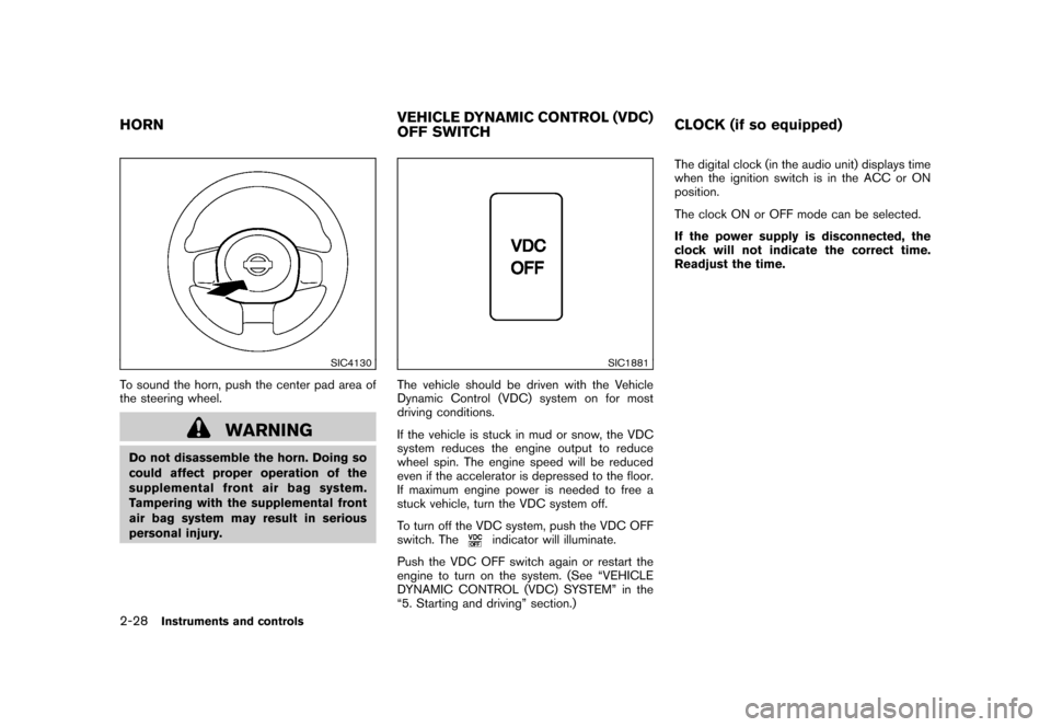
To sound the horn, push the center pad area of
the steering wheel.
WARNING
Do not disassemble the horn. Doing so
could affect proper operation of the
supplemental front air bag system.
Tampering with the supplemental front
air bag system may result in serious
personal injury.
SIC1881
The vehicle should be driven with the Vehicle
Dynamic Control (VDC) system on for most
driving conditions.
If the vehicle is stuck in mud or snow, the VDC
system reduces the engine output to reduce
wheel spin. The engine speed will be reduced
even if the accelerator is depressed to the floor.
If maximum engine power is needed to free a
stuck vehicle, turn the VDC system off.
To turn off the VDC system, push the VDC OFF
switch. The
indicator will illuminate.
Push the VDC OFF switch again or restart the
engine to turn on the system. (See “VEHICLE
DYNAMIC CONTROL (VDC) SYSTEM” in the
“5. Starting and driving” section.) The digital clock (in the audio unit) displays time
when the ignition switch is in the ACC or ON
position.
The clock ON or OFF mode can be selected.
If the power supply is disconnected, the
clock will not indicate the correct time.
Readjust the time.
HORN
VEHICLE DYNAMIC CONTROL (VDC)
OFF SWITCHCLOCK (if so equipped)2-28
Instruments and controls
Page 103 of 329
Black plate (103,1)
Model "Z12-D" EDITED: 2009/ 9/ 17
SIC4131
Type A
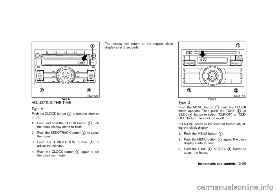
ADJUSTING THE TIME
Type APush the CLOCK button
*1
to turn the clock on
or off.
1. Push and hold the CLOCK button
*1
until
the clock display starts to flash.
2. Push the SEEK/TRACK button
*2
to adjust
the hours.
3. Push the TUNE/ FF·REW button*3
to
adjust the minutes.
4. Push the CLOCK button
*1
again to exit
the clock set mode. The display will return to the regular clock
display after 5 seconds.
SIC4146
Type B
Type BPush the MENU button
*1
until the CLOCK
mode appears. Then push the TUNE
*2
or
SEEK
*3
button to select “CLK-ON” or “CLK-
OFF” to turn the clock on or off.
“CLK-ON” needs to be selected before adjust-
ing the clock display.
1. Push the MENU button
*1.
2. Push the MENU button
*1
again. The clock
display starts to flash.
3. Push the TUNE
*2
or SEEK
*3
button to
adjust the hours.
Instruments and controls
2-29
Page 104 of 329
Black plate (104,1)
Model "Z12-D" EDITED: 2009/ 9/ 17
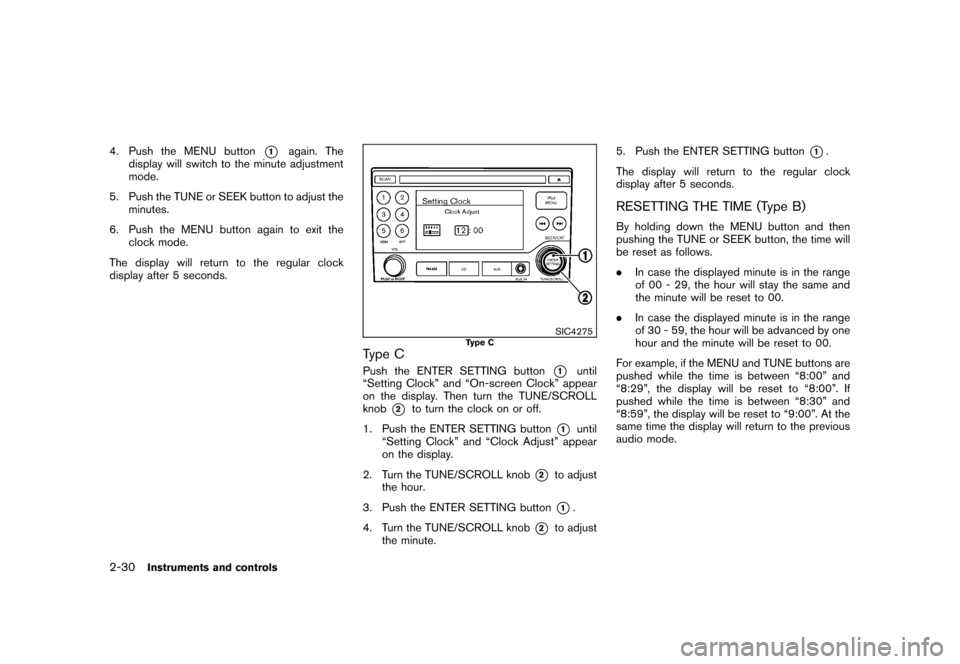
4. Push the MENU button
*1
again. The
display will switch to the minute adjustment
mode.
5. Push the TUNE or SEEK button to adjust the minutes.
6. Push the MENU button again to exit the clock mode.
The display will return to the regular clock
display after 5 seconds.
SIC4275
Type C
Type CPush the ENTER SETTING button
*1
until
“Setting Clock” and “On-screen Clock” appear
on the display. Then turn the TUNE/SCROLL
knob
*2
to turn the clock on or off.
1. Push the ENTER SETTING button
*1
until
“Setting Clock” and “Clock Adjust” appear
on the display.
2. Turn the TUNE/SCROLL knob
*2
to adjust
the hour.
3. Push the ENTER SETTING button*1.
4. Turn the TUNE/SCROLL knob
*2
to adjust
the minute. 5. Push the ENTER SETTING button
*1.
The display will return to the regular clock
display after 5 seconds.
RESETTING THE TIME (Type B)By holding down the MENU button and then
pushing the TUNE or SEEK button, the time will
be reset as follows.
. In case the displayed minute is in the range
of 00 - 29, the hour will stay the same and
the minute will be reset to 00.
. In case the displayed minute is in the range
of 30 - 59, the hour will be advanced by one
hour and the minute will be reset to 00.
For example, if the MENU and TUNE buttons are
pushed while the time is between “8:00” and
“8:29”, the display will be reset to “8:00”. If
pushed while the time is between “8:30” and
“8:59”, the display will be reset to “9:00”. At the
same time the display will return to the previous
audio mode.
2-30
Instruments and controls
Page 138 of 329
Black plate (140,1)
Model "Z12-D" EDITED: 2009/ 9/ 17
SPA2336
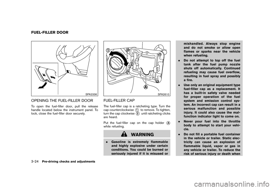
OPENING THE FUEL-FILLER DOORTo open the fuel-filler door, pull the release
handle located below the instrument panel. To
lock, close the fuel-filler door securely.
SPA2610
FUEL-FILLER CAPThe fuel-filler cap is a ratcheting type. Turn the
cap counterclockwise
*1
to remove. To tighten,
turn the cap clockwise
*2
until ratcheting clicks
are heard.
Put the fuel-filler cap on the cap holder
*A
while refueling.
WARNING
. Gasoline is extremely flammable
and highly explosive under certain
conditions. You could be burned or
seriously injured if it is misused or mishandled. Always stop engine
and do not smoke or allow open
flames or sparks near the vehicle
when refueling.
. Do not attempt to top off the fuel
tank after the fuel pump nozzle
shuts off automatically. Continued
refueling may cause fuel overflow,
resulting in fuel spray and possibly
a fire.
. Use only an original equipment type
fuel-filler cap as a replacement. It
has a built-in safety valve needed
for proper operation of the fuel
system and emission control sys-
tem. An incorrect cap can result in a
serious malfunction and possible
injury. It could also cause the mal-
function indicator light to come on.
. Never pour fuel into the throttle
body to attempt to start your vehi-
cle.
. Do not fill a portable fuel container
in the vehicle or trailer. Static elec-
tricity can cause an explosion of
flammable liquid, vapor or gas in
any vehicle or trailer. To reduce the
risk of serious injury or death when
FUEL-FILLER DOOR3-24
Pre-driving checks and adjustments