2010 NISSAN CUBE engine coolant
[x] Cancel search: engine coolantPage 15 of 329
Black plate (11,1)
Model "Z12-D" EDITED: 2009/ 9/ 17
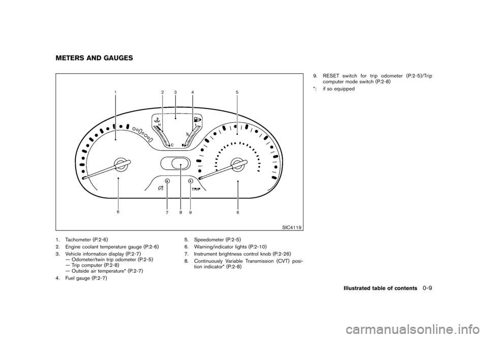
SIC4119
1. Tachometer (P.2-6)
2. Engine coolant temperature gauge (P.2-6)
3. Vehicle information display (P.2-7)— Odometer/twin trip odometer (P.2-5)
— Trip computer (P.2-8)
— Outside air temperature* (P.2-7)
4. Fuel gauge (P.2-7) 5. Speedometer (P.2-5)
6. Warning/indicator lights (P.2-10)
7. Instrument brightness control knob (P.2-26)
8. Continuously Variable Transmission (CVT) posi-
tion indicator* (P.2-8) 9. RESET switch for trip odometer (P.2-5)/Trip
computer mode switch (P.2-8)
*: if so equippedMETERS AND GAUGES
Illustrated table of contents
0-9
Page 16 of 329
Black plate (12,1)
Model "Z12-D" EDITED: 2009/ 9/ 17
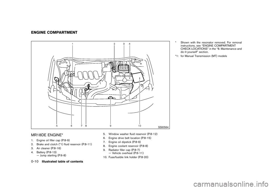
SSI0564
MR18DE ENGINE*1. Engine oil filler cap (P.8-9)
2. Brake and clutch (*1) fluid reservoir (P.8-11)
3. Air cleaner (P.8-16)
4. Battery (P.8-13)— Jump starting (P.6-8) 5. Window washer fluid reservoir (P.8-12)
6. Engine drive belt location (P.8-15)
7. Engine oil dipstick (P.8-9)
8. Engine coolant reservoir (P.8-8)
9. Radiator filler cap (P.8-7)
— Vehicle overheat (P.6-11)
10. Fuse/fusible link holder (P.8-20) * Shown with the resonator removed. For removal
instructions, see “ENGINE COMPARTMENT
CHECK LOCATIONS” in the “8. Maintenance and
do-it-yourself” section.
*1: for Manual Transmission (MT) modelsENGINE COMPARTMENT0-10
Illustrated table of contents
Page 75 of 329
Black plate (7,1)
2 Instruments and controls
Model "Z12-D" EDITED: 2009/ 9/ 17
Cockpit............................................................ 2-2
Instrument panel ................................................ 2-3
Meters and gauges ............................................. 2-4
Speedometer and odometer ............................. 2-5
Tachometer ................................................... 2-6
Engine coolant temperature gauge ..................... 2-6
Fuel gauge ................................................... 2-7
Vehicle information display ................................ 2-7
Outside air temperature (if so equipped) .............. 2-7
Continuously Variable Transmission (CVT)
position indicator (if so equipped) ...................... 2-8
Trip computer ................................................ 2-8
Warning/indicator lights and audible reminders ....... 2-10
Checking bulbs ........................................... 2-10
Warning lights ............................................. 2-10
Indicator lights ............................................. 2-15
Audible reminders ........................................ 2-17
Security systems .............................................. 2-17
Vehicle Security System. ................................ 2-17
NISSAN Vehicle Immobilizer System ................. 2-19
Windshield wiper and washer switch .................... 2-20
Rear window wiper and washer switch .................. 2-22
Rear window and outside mirror defroster switch ..... 2-23Headlight and turn signal switch
.......................... 2-23
Headlight switch .......................................... 2-23
Turn signal switch ........................................ 2-26
Fog light switch (if so equipped) ...................... 2-27
Hazard warning flasher switch ............................. 2-27
Horn ............................................................. 2-28
Vehicle Dynamic Control (VDC) OFF switch ........... 2-28
Clock (if so equipped) ....................................... 2-28
Adjusting the time ........................................ 2-29
Resetting the time (Type B) ............................ 2-30
Power outlet ................................................... 2-31
Storage ......................................................... 2-31
Cup holders ................................................ 2-31
Glove box .................................................. 2-33
Rear pillar pocket ......................................... 2-34
Luggage hooks ............................................ 2-34
Utility hooks (if so equipped) ........................... 2-35
Windows ....................................................... 2-36
Power windows ........................................... 2-36
Interior lights ................................................... 2-38
Map lights (if so equipped) ............................. 2-38
Map light control switch (if so equipped) ........... 2-39
Ceiling light ................................................ 2-39
Cargo light (if so equipped) ................................ 2-40
Page 78 of 329
Black plate (78,1)
Model "Z12-D" EDITED: 2009/ 9/ 17
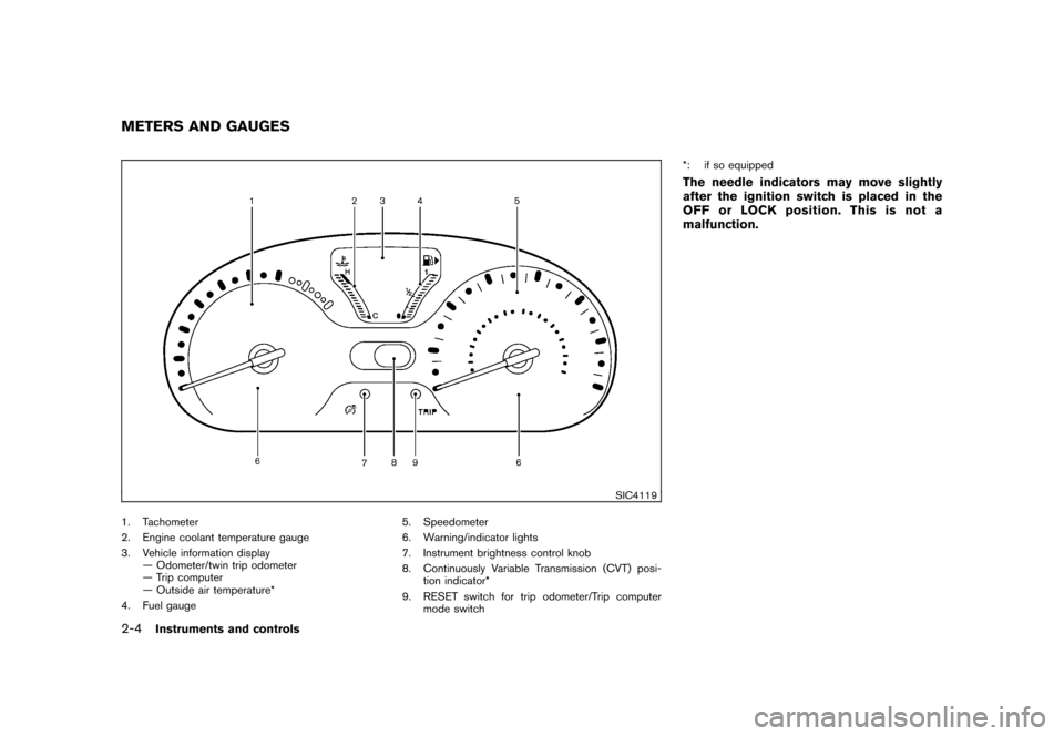
SIC4119
1. Tachometer
2. Engine coolant temperature gauge
3. Vehicle information display— Odometer/twin trip odometer
— Trip computer
— Outside air temperature*
4. Fuel gauge 5. Speedometer
6. Warning/indicator lights
7. Instrument brightness control knob
8. Continuously Variable Transmission (CVT) posi-
tion indicator*
9. RESET switch for trip odometer/Trip computer mode switch *: if so equipped
The needle indicators may move slightly
after the ignition switch is placed in the
OFF or LOCK position. This is not a
malfunction.
METERS AND GAUGES2-4
Instruments and controls
Page 80 of 329
Black plate (80,1)
Model "Z12-D" EDITED: 2009/ 9/ 17
SIC4122
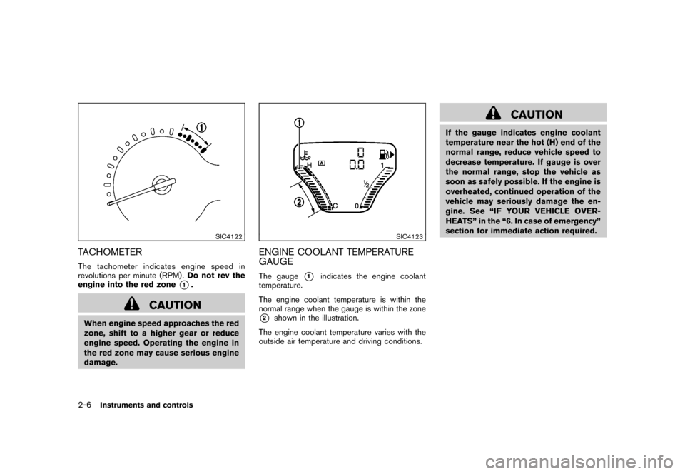
TACHOMETERThe tachometer indicates engine speed in
revolutions per minute (RPM) .Do not rev the
engine into the red zone
*1.
CAUTION
When engine speed approaches the red
zone, shift to a higher gear or reduce
engine speed. Operating the engine in
the red zone may cause serious engine
damage.
SIC4123
ENGINE COOLANT TEMPERATURE
GAUGEThe gauge
*1
indicates the engine coolant
temperature.
The engine coolant temperature is within the
normal range when the gauge is within the zone
*2
shown in the illustration.
The engine coolant temperature varies with the
outside air temperature and driving conditions.
CAUTION
If the gauge indicates engine coolant
temperature near the hot (H) end of the
normal range, reduce vehicle speed to
decrease temperature. If gauge is over
the normal range, stop the vehicle as
soon as safely possible. If the engine is
overheated, continued operation of the
vehicle may seriously damage the en-
gine. See “IF YOUR VEHICLE OVER-
HEATS” in the “6. In case of emergency”
section for immediate action required.
2-6
Instruments and controls
Page 154 of 329
Black plate (158,1)
Model "Z12-D" EDITED: 2009/ 9/ 17
SAA2368SAA2369
OPERATING TIPS.When the engine coolant temperature and
outside air temperature are low, the air flow
from the foot outlets may not operate for a
maximum of 150 seconds. This is not a
malfunction. After the coolant temperature
warms up, air will flow normally from the foot
outlets.
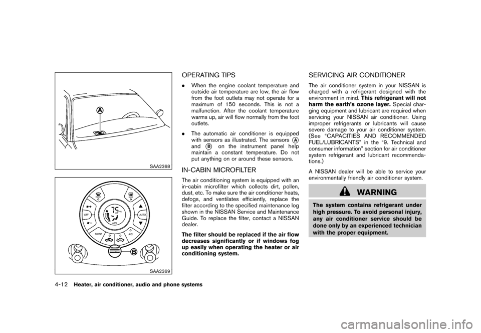
. The automatic air conditioner is equipped
with sensors as illustrated. The sensors
*A
and
*B
on the instrument panel help
maintain a constant temperature. Do not
put anything on or around these sensors.
IN-CABIN MICROFILTERThe air conditioning system is equipped with an
in-cabin microfilter which collects dirt, pollen,
dust, etc. To make sure the air conditioner heats,
defogs, and ventilates efficiently, replace the
filter according to the specified maintenance log
shown in the NISSAN Service and Maintenance
Guide. To replace the filter, contact a NISSAN
dealer.
The filter should be replaced if the air flow
decreases significantly or if windows fog
up easily when operating the heater or air
conditioning system.
SERVICING AIR CONDITIONERThe air conditioner system in your NISSAN is
charged with a refrigerant designed with the
environment in mind. This refrigerant will not
harm the earth’s ozone layer. Special char-
ging equipment and lubricant are required when
servicing your NISSAN air conditioner. Using
improper refrigerants or lubricants will cause
severe damage to your air conditioner system.
(See “CAPACITIES AND RECOMMENDED
FUEL/LUBRICANTS” in the “9. Technical and
consumer information” section for air conditioner
system refrigerant and lubricant recommenda-
tions.)
A NISSAN dealer will be able to service your
environmentally friendly air conditioner system.
WARNING
The system contains refrigerant under
high pressure. To avoid personal injury,
any air conditioner service should be
done only by an experienced technician
with the proper equipment.
4-12
Heater, air conditioner, audio and phone systems
Page 201 of 329
Black plate (16,1)
5 Starting and driving
Model "Z12-D" EDITED: 2009/ 9/ 17
Precautions when starting and driving..................... 5-2
Exhaust gas (carbon monoxide) ......................... 5-2
Three-way catalyst .......................................... 5-2
Tire Pressure Monitoring System (TPMS) ............. 5-3
Avoiding collision and rollover ........................... 5-5
Off-road recovery ........................................... 5-5
Rapid air pressure loss .................................... 5-6
Drinking alcohol/drugs and driving ...................... 5-6
Ignition switch
(models without Intelligent Key system) ................... 5-7
Continuously Variable Transmission (CVT) ............ 5-7
Manual Transmission (MT) ................................ 5-8
Key positions ................................................ 5-8
Push-button ignition switch
(models with Intelligent Key system) ....................... 5-9
Operating range for engine start function ............. 5-9
Push-button ignition switch operation. ............... 5-10
Push-button ignition switch positions ................ 5-10
Intelligent Key battery discharge ...................... 5-11
Before starting the engine .................................. 5-12
Starting the engine ........................................... 5-12
Models without Intelligent Key system ............... 5-12
Models with Intelligent Key system ................... 5-13Driving the vehicle
............................................ 5-14
Continuously Variable Transmission (CVT) .......... 5-14
Manual Transmission (MT) .............................. 5-18
Parking brake .................................................. 5-20
Cruise control (if so equipped) ............................ 5-20
Precautions on cruise control .......................... 5-20
Cruise control operations ............................... 5-21
Break-in schedule ............................................ 5-22
Increasing fuel economy .................................... 5-23
Parking/parking on hills ...................................... 5-24
Electric power steering system ............................ 5-25
Brake system .................................................. 5-26
Braking precautions ...................................... 5-26
Anti-lock Braking System (ABS) ...................... 5-26
Vehicle Dynamic Control (VDC) system ................. 5-28
Cold weather driving ......................................... 5-29
Freeing a frozen door lock .............................. 5-29
Anti-freeze .................................................. 5-29
Battery ...................................................... 5-29
Draining of coolant water ............................... 5-29
Tire equipment ............................................ 5-30
Special winter equipment ............................... 5-30
Driving on snow or ice .................................. 5-30
Engine block heater (if so equipped) ................. 5-30
Page 220 of 329
Black plate (224,1)
Model "Z12-D" EDITED: 2009/ 9/ 17
WARNING
.Be sure the parking brake is fully
released before driving. Failure to
do so can cause brake failure and
lead to an accident.
. Do not release the parking brake
from outside the vehicle.
. Do not use the gear shift in place of
the parking brake. When parking, be
sure the parking brake is fully
engaged.
. Do not leave children unattended in
a vehicle. They could release the
parking brake and cause an acci-
dent.
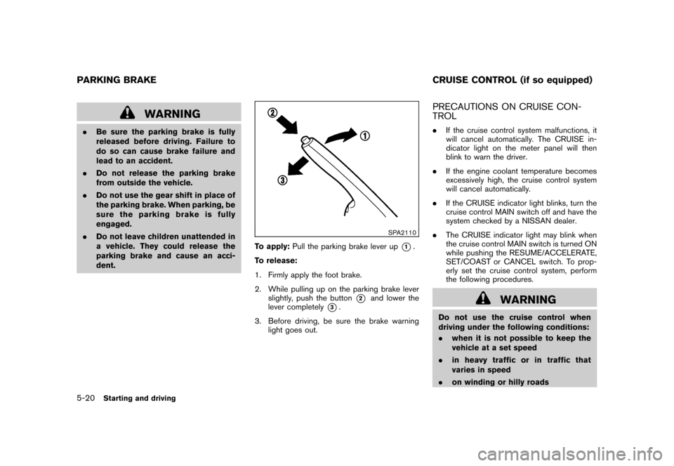
SPA2110
To apply: Pull the parking brake lever up
*1.
To release:
1. Firmly apply the foot brake.
2. While pulling up on the parking brake lever slightly, push the button
*2
and lower the
lever completely
*3.
3. Before driving, be sure the brake warning light goes out.
PRECAUTIONS ON CRUISE CON-
TROL.If the cruise control system malfunctions, it
will cancel automatically. The CRUISE in-
dicator light on the meter panel will then
blink to warn the driver.
. If the engine coolant temperature becomes
excessively high, the cruise control system
will cancel automatically.
. If the CRUISE indicator light blinks, turn the
cruise control MAIN switch off and have the
system checked by a NISSAN dealer.
. The CRUISE indicator light may blink when
the cruise control MAIN switch is turned ON
while pushing the RESUME/ACCELERATE,
SET/COAST or CANCEL switch. To prop-
erly set the cruise control system, perform
the following procedures.
WARNING
Do not use the cruise control when
driving under the following conditions:
.when it is not possible to keep the
vehicle at a set speed
. in heavy traffic or in traffic that
varies in speed
. on winding or hilly roads
PARKING BRAKE CRUISE CONTROL (if so equipped)5-20
Starting and driving