2010 NISSAN CUBE warning lights
[x] Cancel search: warning lightsPage 15 of 329
Black plate (11,1)
Model "Z12-D" EDITED: 2009/ 9/ 17
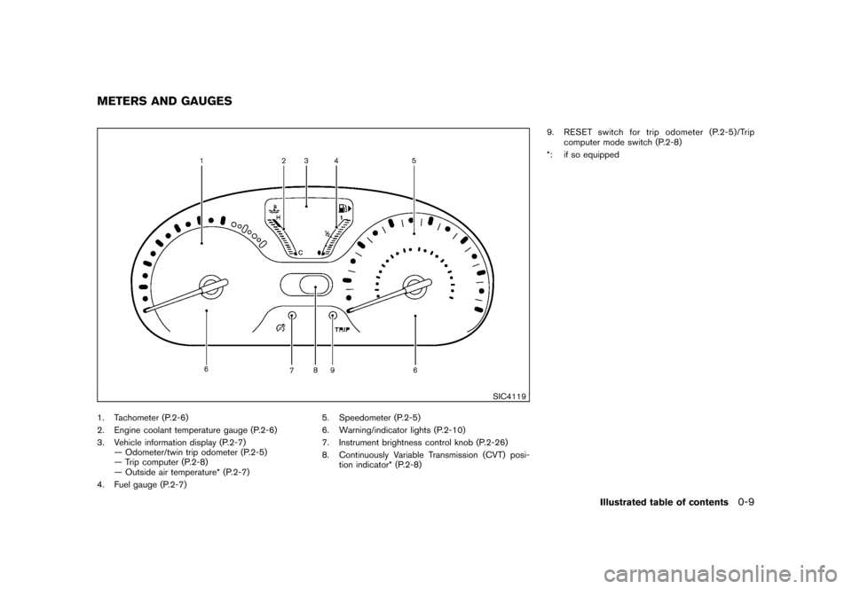
SIC4119
1. Tachometer (P.2-6)
2. Engine coolant temperature gauge (P.2-6)
3. Vehicle information display (P.2-7)— Odometer/twin trip odometer (P.2-5)
— Trip computer (P.2-8)
— Outside air temperature* (P.2-7)
4. Fuel gauge (P.2-7) 5. Speedometer (P.2-5)
6. Warning/indicator lights (P.2-10)
7. Instrument brightness control knob (P.2-26)
8. Continuously Variable Transmission (CVT) posi-
tion indicator* (P.2-8) 9. RESET switch for trip odometer (P.2-5)/Trip
computer mode switch (P.2-8)
*: if so equippedMETERS AND GAUGES
Illustrated table of contents
0-9
Page 75 of 329
Black plate (7,1)
2 Instruments and controls
Model "Z12-D" EDITED: 2009/ 9/ 17
Cockpit............................................................ 2-2
Instrument panel ................................................ 2-3
Meters and gauges ............................................. 2-4
Speedometer and odometer ............................. 2-5
Tachometer ................................................... 2-6
Engine coolant temperature gauge ..................... 2-6
Fuel gauge ................................................... 2-7
Vehicle information display ................................ 2-7
Outside air temperature (if so equipped) .............. 2-7
Continuously Variable Transmission (CVT)
position indicator (if so equipped) ...................... 2-8
Trip computer ................................................ 2-8
Warning/indicator lights and audible reminders ....... 2-10
Checking bulbs ........................................... 2-10
Warning lights ............................................. 2-10
Indicator lights ............................................. 2-15
Audible reminders ........................................ 2-17
Security systems .............................................. 2-17
Vehicle Security System. ................................ 2-17
NISSAN Vehicle Immobilizer System ................. 2-19
Windshield wiper and washer switch .................... 2-20
Rear window wiper and washer switch .................. 2-22
Rear window and outside mirror defroster switch ..... 2-23Headlight and turn signal switch
.......................... 2-23
Headlight switch .......................................... 2-23
Turn signal switch ........................................ 2-26
Fog light switch (if so equipped) ...................... 2-27
Hazard warning flasher switch ............................. 2-27
Horn ............................................................. 2-28
Vehicle Dynamic Control (VDC) OFF switch ........... 2-28
Clock (if so equipped) ....................................... 2-28
Adjusting the time ........................................ 2-29
Resetting the time (Type B) ............................ 2-30
Power outlet ................................................... 2-31
Storage ......................................................... 2-31
Cup holders ................................................ 2-31
Glove box .................................................. 2-33
Rear pillar pocket ......................................... 2-34
Luggage hooks ............................................ 2-34
Utility hooks (if so equipped) ........................... 2-35
Windows ....................................................... 2-36
Power windows ........................................... 2-36
Interior lights ................................................... 2-38
Map lights (if so equipped) ............................. 2-38
Map light control switch (if so equipped) ........... 2-39
Ceiling light ................................................ 2-39
Cargo light (if so equipped) ................................ 2-40
Page 78 of 329
Black plate (78,1)
Model "Z12-D" EDITED: 2009/ 9/ 17
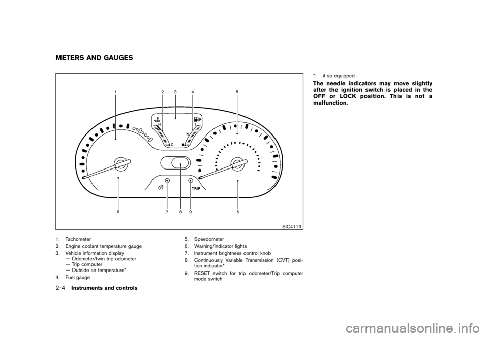
SIC4119
1. Tachometer
2. Engine coolant temperature gauge
3. Vehicle information display— Odometer/twin trip odometer
— Trip computer
— Outside air temperature*
4. Fuel gauge 5. Speedometer
6. Warning/indicator lights
7. Instrument brightness control knob
8. Continuously Variable Transmission (CVT) posi-
tion indicator*
9. RESET switch for trip odometer/Trip computer mode switch *: if so equipped
The needle indicators may move slightly
after the ignition switch is placed in the
OFF or LOCK position. This is not a
malfunction.
METERS AND GAUGES2-4
Instruments and controls
Page 84 of 329
Black plate (84,1)
Model "Z12-D" EDITED: 2009/ 9/ 17
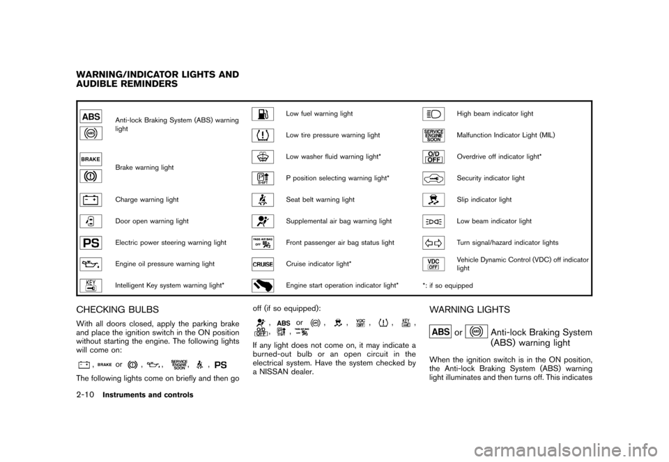
Anti-lock Braking System (ABS) warning
light
Low fuel warning light
High beam indicator light
Low tire pressure warning light
Malfunction Indicator Light (MIL)
Brake warning light
Low washer fluid warning light*
Overdrive off indicator light*
P position selecting warning light*
Security indicator light
Charge warning light
Seat belt warning light
Slip indicator light
Door open warning light
Supplemental air bag warning light
Low beam indicator light
Electric power steering warning light
Front passenger air bag status light
Turn signal/hazard indicator lights
Engine oil pressure warning light
Cruise indicator light*
Vehicle Dynamic Control (VDC) off indicator
light
Intelligent Key system warning light*
Engine start operation indicator light**: if so equipped
CHECKING BULBSWith all doors closed, apply the parking brake
and place the ignition switch in the ON position
without starting the engine. The following lights
will come on:
,
or
,
,
,
,
The following lights come on briefly and then go off (if so equipped):
,
or
,
,
,
,
,
,
,
If any light does not come on, it may indicate a
burned-out bulb or an open circuit in the
electrical system. Have the system checked by
a NISSAN dealer.
WARNING LIGHTS
or
Anti-lock Braking System
(ABS) warning light
When the ignition switch is in the ON position,
the Anti-lock Braking System (ABS) warning
light illuminates and then turns off. This indicates
WARNING/INDICATOR LIGHTS AND
AUDIBLE REMINDERS2-10
Instruments and controls
Page 89 of 329
Black plate (89,1)
Model "Z12-D" EDITED: 2009/ 9/ 17
WARNING
If the supplemental air bag warning
light is on, it could mean that the front
air bag, side air bag, curtain air bag
and/or pretensioner systems will not
operate in an accident. To help avoid
injury to yourself or others, have your
vehicle checked by a NISSAN dealer as
soon as possible.INDICATOR LIGHTS
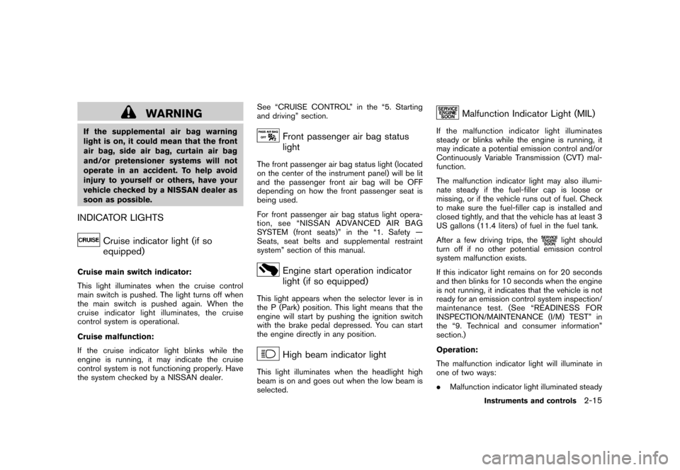
Cruise indicator light (if so
equipped)
Cruise main switch indicator:
This light illuminates when the cruise control
main switch is pushed. The light turns off when
the main switch is pushed again. When the
cruise indicator light illuminates, the cruise
control system is operational.
Cruise malfunction:
If the cruise indicator light blinks while the
engine is running, it may indicate the cruise
control system is not functioning properly. Have
the system checked by a NISSAN dealer.See “CRUISE CONTROL” in the “5. Starting
and driving” section.
Front passenger air bag status
light
The front passenger air bag status light (located
on the center of the instrument panel) will be lit
and the passenger front air bag will be OFF
depending on how the front passenger seat is
being used.
For front passenger air bag status light opera-
tion,see“NISSANADVANCEDAIRBAG
SYSTEM (front seats)” in the “1. Safety —
Seats, seat belts and supplemental restraint
system” section of this manual.
Engine start operation indicator
light (if so equipped)
This light appears when the selector lever is in
the P (Park) position. This light means that the
engine will start by pushing the ignition switch
with the brake pedal depressed. You can start
the engine directly in any position.
High beam indicator light
This light illuminates when the headlight high
beam is on and goes out when the low beam is
selected.
Malfunction Indicator Light (MIL)
If the malfunction indicator light illuminates
steady or blinks while the engine is running, it
may indicate a potential emission control and/or
Continuously Variable Transmission (CVT) mal-
function.
The malfunction indicator light may also illumi-
nate steady if the fuel-filler cap is loose or
missing, or if the vehicle runs out of fuel. Check
to make sure the fuel-filler cap is installed and
closed tightly, and that the vehicle has at least 3
US gallons (11.4 liters) of fuel in the fuel tank.
After a few driving trips, the
light should
turn off if no other potential emission control
system malfunction exists.
If this indicator light remains on for 20 seconds
and then blinks for 10 seconds when the engine
is not running, it indicates that the vehicle is not
ready for an emission control system inspection/
maintenance test. (See “READINESS FOR
INSPECTION/MAINTENANCE (I/M) TEST” in
the “9. Technical and consumer information”
section.)
Operation:
The malfunction indicator light will illuminate in
one of two ways:
. Malfunction indicator light illuminated steady
Instruments and controls
2-15
Page 99 of 329
Black plate (99,1)
Model "Z12-D" EDITED: 2009/ 9/ 17
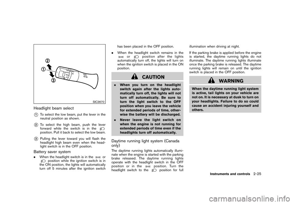
SIC3670
Headlight beam select*1
To select the low beam, put the lever in the
neutral position as shown.
*2
To select the high beam, push the lever
forward while the switch is in theposition. Pull it back to select the low beam.
*3
Pulling the lever toward you will flash the
headlight high beam even when the head-
light switch is in the OFF position.
Battery saver system.When the headlight switch is in the
or
position while the ignition switch is in
the ON position, the lights will automatically
turn off 5 minutes after the ignition switch has been placed in the OFF position.
. When the headlight switch remains in the
or
position after the lights
automatically turn off, the lights will turn on
when the ignition switch is placed in the ON
position.CAUTION
. When you turn on the headlight
switch again after the lights auto-
matically turn off, the lights will not
turn off automatically. Be sure to
turn the light switch to the OFF
position when you leave the vehicle
for extended periods of time, other-
wise the battery will be discharged.
. Never leave the light switch on
when the engine is not running for
extended periods of time even if the
headlights turn off automatically.Daytime running light system (Canada
only)The daytime running lights automatically illumi-
nate when the engine is started with the parking
brake released. The daytime running lights
operate with the headlight switch in the OFF
position or in the
position. Turn the
headlight switch to the
position for full illumination when driving at night.
If the parking brake is applied before the engine
is started, the daytime running lights do not
illuminate. The daytime running lights illuminate
once the parking brake is released. The daytime
running lights will remain on until the ignition
switch is placed in the OFF position.
WARNING
When the daytime running light system
is active, tail lights on your vehicle are
not on. It is necessary at dusk to turn on
your headlights. Failure to do so could
cause an accident injuring yourself and
others.
Instruments and controls
2-25
Page 101 of 329
Black plate (101,1)
Model "Z12-D" EDITED: 2009/ 9/ 17
SIC3672
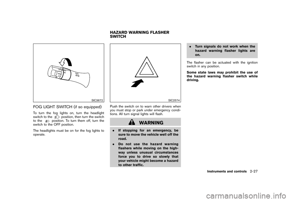
FOG LIGHT SWITCH (if so equipped)To turn the fog lights on, turn the headlight
switch to the
position, then turn the switch
to the
position. To turn them off, turn the
switch to the OFF position.
The headlights must be on for the fog lights to
operate.
SIC2574
Push the switch on to warn other drivers when
you must stop or park under emergency condi-
tions. All turn signal lights will flash.
WARNING
. If stopping for an emergency, be
sure to move the vehicle well off the
road.
. Do not use the hazard warning
flashers while moving on the high-
way unless unusual circumstances
force you to drive so slowly that
your vehicle might become a hazard
to other traffic. .
Turn signals do not work when the
hazard warning flasher lights are
on.
The flasher can be actuated with the ignition
switch in any position.
Some state laws may prohibit the use of
the hazard warning flasher switch while
driving.HAZARD WARNING FLASHER
SWITCH
Instruments and controls
2-27
Page 115 of 329
Black plate (10,1)
3 Pre-driving checks and adjustments
Model "Z12-D" EDITED: 2009/ 9/ 17
Keys ............................................................... 3-2NISSAN Vehicle Immobilizer System keys ............ 3-2
Intelligent Keys (if so equipped) ......................... 3-3
Doors .............................................................. 3-4
Locking with key ............................................ 3-4
Locking with inside lock knob ........................... 3-5
Locking with power door lock switch .................. 3-5
Automatic door locks ...................................... 3-5
Child safety rear door lock ............................... 3-6
Remote keyless entry system (if so equipped) ........... 3-6
How to use remote keyless entry system ............. 3-7
Intelligent Key system (if so equipped) .................. 3-10
Intelligent Key operating range ........................ 3-12
Door locks/unlocks precaution ........................ 3-12
Intelligent Key operation ................................. 3-13
Battery saver system ..................................... 3-14 Warning lights and audible reminders
............... 3-14
Troubleshooting guide ................................... 3-15
How to use remote keyless entry function .......... 3-17
Hood ............................................................ 3-21
Back door ...................................................... 3-22
Bumpers and side sill extensions (Kro ¯
m models) . .... 3-23
Fuel-filler door ................................................. 3-24
Opening the fuel-filler door ............................. 3-24
Fuel-filler cap .............................................. 3-24
Tilt steering column .......................................... 3-25
Tilt operation ............................................... 3-26
Sun visors ...................................................... 3-26
Mirrors ........................................................... 3-26
Inside mirror ................................................ 3-26
Outside mirrors ............................................ 3-27