2010 NISSAN CUBE battery
[x] Cancel search: batteryPage 209 of 329
Black plate (213,1)
Model "Z12-D" EDITED: 2009/ 9/ 17
WARNING
Do not operate the push-button ignition
switch while driving the vehicle except
in an emergency. (The engine will stop
when the ignition switch is pushed 3
consecutive times or the ignition switch
is pushed and held for more than 2
seconds.) If the engine stops while the
vehicle is being driven, this could lead
to a crash and serious injury.
Before operating the push-button ignition
switch, be sure to move the selector lever to
the P (Park) position.
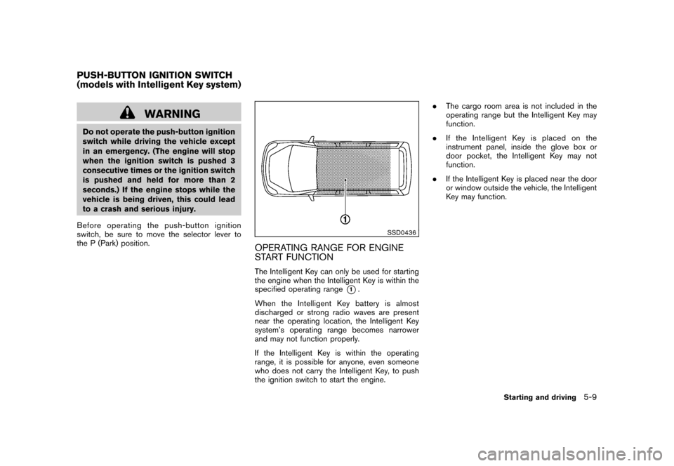
SSD0436
OPERATING RANGE FOR ENGINE
START FUNCTIONThe Intelligent Key can only be used for starting
the engine when the Intelligent Key is within the
specified operating range
*1.
When the Intelligent Key battery is almost
discharged or strong radio waves are present
near the operating location, the Intelligent Key
system’s operating range becomes narrower
and may not function properly.
If the Intelligent Key is within the operating
range, it is possible for anyone, even someone
who does not carry the Intelligent Key, to push
the ignition switch to start the engine. .
The cargo room area is not included in the
operating range but the Intelligent Key may
function.
. If the Intelligent Key is placed on the
instrument panel, inside the glove box or
door pocket, the Intelligent Key may not
function.
. If the Intelligent Key is placed near the door
or window outside the vehicle, the Intelligent
Key may function.
PUSH-BUTTON IGNITION SWITCH
(models with Intelligent Key system)
Starting and driving
5-9
Page 210 of 329
Black plate (214,1)
Model "Z12-D" EDITED: 2009/ 9/ 17
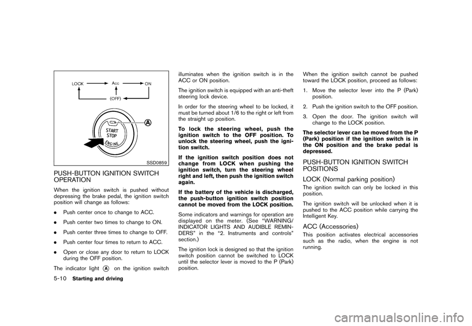
SSD0859
PUSH-BUTTON IGNITION SWITCH
OPERATIONWhen the ignition switch is pushed without
depressing the brake pedal, the ignition switch
position will change as follows:
.Push center once to change to ACC.
. Push center two times to change to ON.
. Push center three times to change to OFF.
. Push center four times to return to ACC.
. Open or close any door to return to LOCK
during the OFF position.
The indicator light
*A
on the ignition switch illuminates when the ignition switch is in the
ACC or ON position.
The ignition switch is equipped with an anti-theft
steering lock device.
In order for the steering wheel to be locked, it
must be turned about 1/6 to the right or left from
the straight up position.
To lock the steering wheel, push the
ignition switch to the OFF position. To
unlock the steering wheel, push the igni-
tion switch.
If the ignition switch position does not
change from LOCK when pushing the
ignition switch, turn the steering wheel
right and left, then push the ignition switch
again.
If the battery of the vehicle is discharged,
the push-button ignition switch position
cannot be moved from the LOCK position.
Some indicators and warnings for operation are
displayed on the meter. (See “WARNING/
INDICATOR LIGHTS AND AUDIBLE REMIN-
DERS” in the “2. Instruments and controls”
section.)
The ignition lock is designed so that the ignition
switch position cannot be switched to LOCK
until the selector lever is moved to the P (Park)
position.
When the ignition switch cannot be pushed
toward the LOCK position, proceed as follows:
1. Move the selector lever into the P (Park)
position.
2. Push the ignition switch to the OFF position.
3. Open the door. The ignition switch will change to the LOCK position.
The selector lever can be moved from the P
(Park) position if the ignition switch is in
the ON position and the brake pedal is
depressed.
PUSH-BUTTON IGNITION SWITCH
POSITIONS
LOCK (Normal parking position)The ignition switch can only be locked in this
position.
The ignition switch will be unlocked when it is
pushed to the ACC position while carrying the
Intelligent Key.ACC (Accessories)This position activates electrical accessories
such as the radio, when the engine is not
running.
5-10
Starting and driving
Page 211 of 329
Black plate (215,1)
Model "Z12-D" EDITED: 2009/ 9/ 17
ON (Normal operating position)This position turns on the ignition system and
electrical accessories.OFFThe engine can be turned off without locking the
steering wheel.
The ignition lock is designed so that the ignition
switch cannot be switched to the LOCK position
until the selector lever is moved to the P (Park)
position.
CAUTION
Do not leave the vehicle with the push-
button ignition switch in ACC or ON
position when the engine is not running
for an extended period. This can dis-
charge the battery.
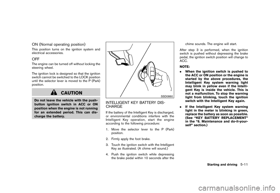
SSD0860
INTELLIGENT KEY BATTERY DIS-
CHARGEIf the battery of the Intelligent Key is discharged,
or environmental conditions interfere with the
Intelligent Key operation, start the engine
according to the following procedure:
1. Move the selector lever to the P (Park)position.
2. Firmly apply the foot brake.
3. Touch the ignition switch with the Intelligent Key as illustrated. (A chime will sound.)
4. Push the ignition switch while depressing the brake pedal within 10 seconds after the chime sounds. The engine will start.
After step 3 is performed, when the ignition
switch is pushed without depressing the brake
pedal, the ignition switch position will change to
ACC.
NOTE:
. When the ignition switch is pushed to
the ACC or ON position or the engine is
started by the above procedures, the
Intelligent Key system warning light
may blink in yellow even if the Intelli-
gent Key is inside the vehicle. This is
not a malfunction. To stop the warning
light from blinking, touch the ignition
switch with the Intelligent Key again.
. If the Intelligent Key system warning
light in the meter is blinking in green,
replace the battery as soon as possible.
(See “KEY BATTERY REPLACEMENT”
in the “8. Maintenance and do-it-your-
self” section.)
Starting and driving
5-11
Page 217 of 329
Black plate (221,1)
Model "Z12-D" EDITED: 2009/ 9/ 17
ON position. The vehicle should return to
its normal operating condition. If it does
not return to its normal operating condi-
tion, have a NISSAN dealer check the
transmission and repair if necessary.
WARNING
When the high fluid temperature pro-
tection mode or fail-safe operation
occurs, vehicle speed may be gradually
reduced. The reduced speed may be
lower than other traffic, which could
increase the chance of a collision. Be
especially careful when driving. If ne-
cessary, pull to the side of the road at a
safe place and allow the transmission
to return to normal operation, or have it
repaired if necessary.
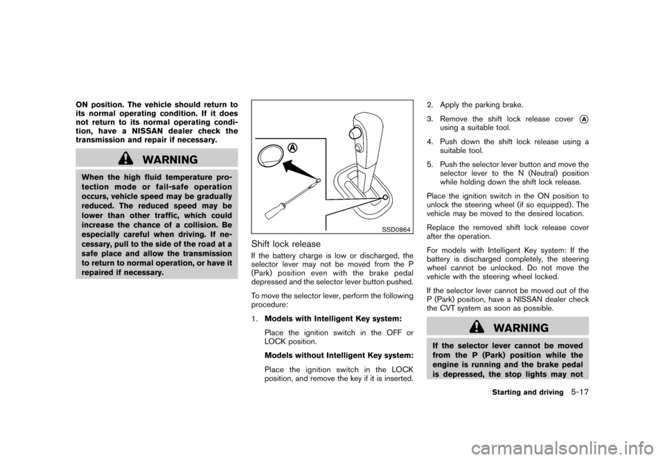
SSD0864
Shift lock releaseIf the battery charge is low or discharged, the
selector lever may not be moved from the P
(Park) position even with the brake pedal
depressed and the selector lever button pushed.
To move the selector lever, perform the following
procedure:
1.Models with Intelligent Key system:
Place the ignition switch in the OFF or
LOCK position.
Models without Intelligent Key system:
Place the ignition switch in the LOCK
position, and remove the key if it is inserted. 2. Apply the parking brake.
3. Remove the shift lock release cover
*A
using a suitable tool.
4. Push down the shift lock release using a suitable tool.
5. Push the selector lever button and move the selector lever to the N (Neutral) position
while holding down the shift lock release.
Place the ignition switch in the ON position to
unlock the steering wheel (if so equipped) . The
vehicle may be moved to the desired location.
Replace the removed shift lock release cover
after the operation.
For models with Intelligent Key system: If the
battery is discharged completely, the steering
wheel cannot be unlocked. Do not move the
vehicle with the steering wheel locked.
If the selector lever cannot be moved out of the
P (Park) position, have a NISSAN dealer check
the CVT system as soon as possible.
WARNING
If the selector lever cannot be moved
from the P (Park) position while the
engine is running and the brake pedal
is depressed, the stop lights may not
Starting and driving
5-17
Page 229 of 329
Black plate (233,1)
Model "Z12-D" EDITED: 2009/ 9/ 17
indicator lights may illuminate.
. If brake related parts such as brake
pads, rotors and calipers are not
NISSAN recommended or are extre-
mely deteriorated, the VDC system
may not operate properly and bothand
indicator lights may
illuminate.
. If engine control related parts are
not NISSAN recommended or are
extremely deteriorated, both the
and
indicator lights may
illuminate.
. When driving on extremely inclined
surfaces such as higher banked
corners, the VDC system may not
operate properly and the
in-
dicator may flash or bothand
indicator lights may illuminate.
Do not drive on these types of
roads.
. When driving on an unstable sur-
face such as a turntable, ferry,
elevator or ramp, the
indicator
may flash or bothand
indicator lights may illuminate. This
is not a malfunction. Restart the
engine after driving onto a stable surface.
. If wheels or tires other than the
NISSAN recommended ones are
used, the VDC system may not
operate properly and the
in-
dicator may flash or bothand
indicator lights may illuminate.
. The VDC system is not a substitute
for winter tires or tire chains on a
snow covered road.
FREEING A FROZEN DOOR LOCKTo prevent a door lock from freezing, apply
deicer through the key hole. If the lock becomes
frozen, heat the key before inserting it into the
key hole or use the remote keyless entry keyfob.ANTI-FREEZEIn the winter when it is anticipated that the
outside temperature will drop below 32 8F(0 8C) ,
check the anti-freeze to assure proper winter
protection. For additional information, see “EN-
GINE COOLING SYSTEM” in the “8. Main-
tenance and do-it-yourself” section.BATTERYIf the battery is not fully charged during
extremely cold weather conditions, the battery
fluid may freeze and damage the battery. To
maintain maximum efficiency, the battery should
be checked regularly. For additional information,
see “BATTERY” in the “8. Maintenance and do-
it-yourself” section.DRAINING OF COOLANT WATERIf the vehicle is to be left outside without anti-
freeze, drain the cooling system, including the
engine block. Refill before operating the vehicle.
For details, see “ENGINE COOLING SYSTEM”
in the “8. Maintenance and do-it-yourself”
section.COLD WEATHER DRIVING
Starting and driving
5-29
Page 240 of 329
Black plate (244,1)
Model "Z12-D" EDITED: 2009/ 9/ 17
SCE0828
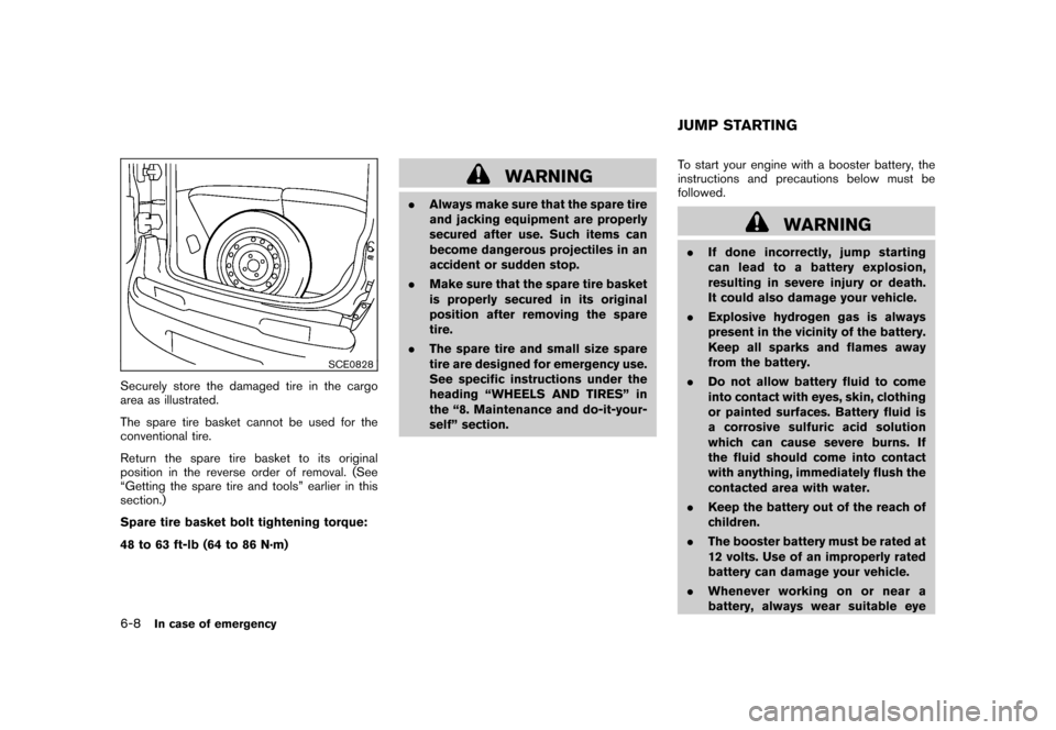
Securely store the damaged tire in the cargo
area as illustrated.
The spare tire basket cannot be used for the
conventional tire.
Return the spare tire basket to its original
position in the reverse order of removal. (See
“Getting the spare tire and tools” earlier in this
section.)
Spare tire basket bolt tightening torque:
48 to 63 ft-lb (64 to 86 N·m)
WARNING
.Always make sure that the spare tire
and jacking equipment are properly
secured after use. Such items can
become dangerous projectiles in an
accident or sudden stop.
. Make sure that the spare tire basket
is properly secured in its original
position after removing the spare
tire.
. The spare tire and small size spare
tire are designed for emergency use.
See specific instructions under the
heading “WHEELS AND TIRES” in
the “8. Maintenance and do-it-your-
self” section. To start your engine with a booster battery, the
instructions and precautions below must be
followed.
WARNING
.
If done incorrectly, jump starting
can lead to a battery explosion,
resulting in severe injury or death.
It could also damage your vehicle.
. Explosive hydrogen gas is always
present in the vicinity of the battery.
Keep all sparks and flames away
from the battery.
. Do not allow battery fluid to come
into contact with eyes, skin, clothing
or painted surfaces. Battery fluid is
a corrosive sulfuric acid solution
which can cause severe burns. If
the fluid should come into contact
with anything, immediately flush the
contacted area with water.
. Keep the battery out of the reach of
children.
. The booster battery must be rated at
12 volts. Use of an improperly rated
battery can damage your vehicle.
. Whenever working on or near a
battery, always wear suitable eyeJUMP STARTING
6-8
In case of emergency
Page 241 of 329
Black plate (245,1)
Model "Z12-D" EDITED: 2009/ 9/ 17
protectors (for example, goggles or
industrial safetyspectacles) and
remove rings, metal bands, or any
other jewelry. Do not lean over the
battery when jump starting.
. Do not attempt to jump start a
frozen battery. It could explode
and cause serious injury.
. Your vehicle has an automatic en-
gine cooling fan. It could come on at
any time. Keep hands and other
objects away from it.
SCE0862
WARNING
Always follow the instructions below.
Failure to do so could result in damage
to the charging system and cause
personal injury.
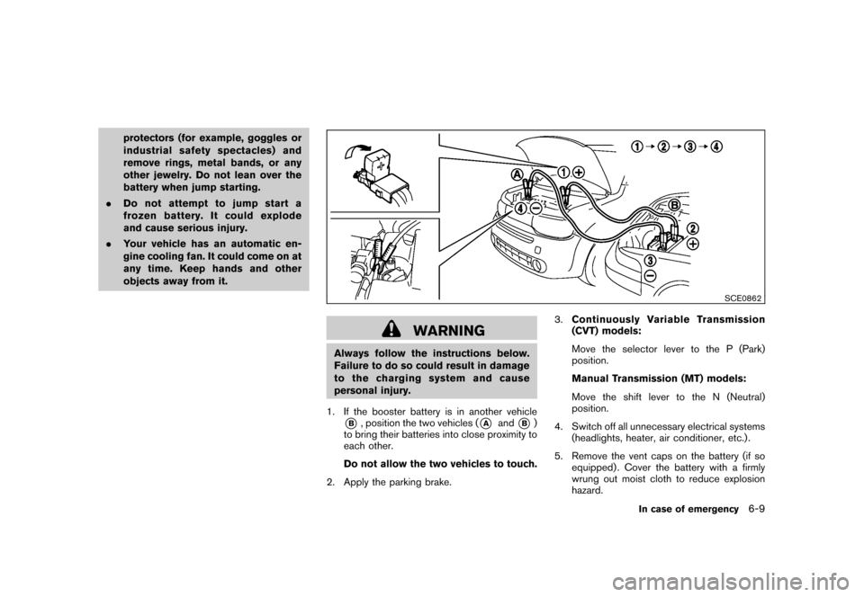
1. If the booster battery is in another vehicle*B, position the two vehicles (
*A
and
*B)
to bring their batteries into close proximity to
each other.
Do not allow the two vehicles to touch.
2. Apply the parking brake. 3.
Continuously Variable Transmission
(CVT) models:
Move the selector lever to the P (Park)
position.
Manual Transmission (MT) models:
Move the shift lever to the N (Neutral)
position.
4. Switch off all unnecessary electrical systems (headlights, heater, air conditioner, etc.) .
5. Remove the vent caps on the battery (if so equipped) . Cover the battery with a firmly
wrung out moist cloth to reduce explosion
hazard.
In case of emergency
6-9
Page 242 of 329
Black plate (246,1)
Model "Z12-D" EDITED: 2009/ 9/ 17
6. Connect jumper cables in the sequence asillustrated (
*1
?
*2
?
*3
?
*4).
For the vehicle equipped with Intelli-
gent Key system:
If the battery is discharged, the ignition
switch cannot be moved from the OFF
position and, if the steering lock is
engaged, the steering wheel cannot be
moved. Connect the jumper cables to
the booster vehicle
*B
before turning
the ignition switch and disengaging the
steering lock.
CAUTION
. Always connect positive (+) to posi-
tive (+) and negative ( �) to body
ground (for example, as illustrated) ,
not to the battery.
. Make sure the jumper cables do not
touch moving parts in the engine
compartment and that the cable
clamps do not contact any other
metal.
7. Start the engine of the booster vehicle
*B
and let it run for a few minutes.
8. Keep the engine speed of the booster vehicle
*B
at about 2,000 rpm, and start the engine of the vehicle
*A
being jump
started.
CAUTION
Do not keep the starter motor engaged
for more than 10 seconds. If the engine
does not start right away, place the
ignition switch in the OFF position and
wait 10 seconds before trying again.
9. After starting your engine, carefully discon- nect the negative cable and then the positive
cable (
*4
?
*3
?
*2
?
*1).
10. Replace the vent caps (if so equipped) . Be sure to dispose of the cloth used to cover
the vent holes as it may be contaminated
with corrosive acid. Do not attempt to start the engine by pushing.
CAUTION
.
Continuously Variable Transmission
(CVT) models cannot be push-
started or tow-started. Attempting
to do so may cause transmission
damage.
. Three-way catalyst equipped mod-
els should not be started by pushing
since the three way catalyst may be
damaged.
. Never try to start the vehicle by
towing it; when the engine starts,
the forward surge could cause the
vehicle to collide with the tow
vehicle.PUSH STARTING
6-10
In case of emergency