Page 308 of 472
1. Press the INFO button on the instrumentpanel.
2. Highlight the “Others” key using the NISSAN controller and press the ENTER
button.
3. Highlight the “Voice Recognition” key using the NISSAN controller and press the ENTER
button. NOTE:
You can skip steps 1 to 3 by pressing
the
Page 321 of 472
Only manual controls such as the touch screen
can navigate the command list menu.
As an alternative to the voice command “Help”,
you may access the command list using the fol-
lowing steps:1. Press the INFO button on the instrument
panel.
2. Highlight the “Others” key using the NISSAN controller and press the ENTER
button.
3. Highlight the “Voice Recognition” key using the NISSAN controller and press the ENTER
button.
NOTE:
You can skip steps 1 to 3 if you say “Help”. 4. Highlight the “Command List” key using the NISSAN controller and press the ENTER
button. 5. Highlight a category using the NISSAN con-
troller and press the ENTER button. The
command list for the category selected is
shown.
6. If necessary, scroll the screen using the NISSAN controller to view the entire list.
7. Press the BACK button to return to the previous screen.
Page 325 of 472
Displaying user guide
You can confirm how to use voice commands by
accessing a simplified User Guide, which con-
tains basic instructions and tutorials for several
voice commands.1. Press the INFO button on the instrument panel.
2. Highlight the “Others” key using the NISSAN controller and press the ENTER
button.
3. Highlight the “Voice Recognition” key using the NISSAN controller and press the ENTER
button. 4. Highlight the “User Guide” key using the
NISSAN controller and press the ENTER
button.
5. Highlight an item using the NISSAN control-ler and press the ENTER button.
Available items: ● Getting Started
Describes the basics of how to operate the
Voice Recognition system.
● Using the Address Book
Tutorial for using the Address Book.
● Finding a Street Address
Tutorial for Finding a Street Address.
Page 361 of 472

pedal. This is normal and does not indicate a
malfunction. If the computer senses a malfunc-
tion, it switches the ABS off and illuminates the
ABS warning light on the instrument panel. The
brake system then operates normally, but without
anti-lock assistance.
If the ABS warning light illuminates during the
self-test or while driving, have the vehicle
checked by a NISSAN dealer.The Vehicle Dynamic Control (VDC) system uses
various sensors to monitor driver inputs and ve-
hicle motion. Under certain situations, the system
will control braking and engine output to help
keep the vehicle on its steered path.
● When the Vehicle Dynamic Control (VDC)
system is operating, the slip indicator in the
instrument panel blinks.
● If the slip indicator blinks, the road condi-
tions may be slippery. Be sure to adjust your
speed and driving to these conditions. See
“Slip indicator light”, and “Vehicle Dynamic
Control (VDC) off indicator light” in the “In-
struments and controls” section.
● Indicator light
– If a malfunction occurs in the system, the SLIP and
Page 363 of 472

●The system is designed as an aid to the
driver in detecting large stationary ob-
jects to help avoid damaging the ve-
hicle. The system will not detect small
objects below the bumper, and may not
detect objects close to the bumper or
on the ground.
● If your vehicle sustains damage to the
rear bumper fascia, leaving it mis-
aligned or bent, the sensing zone may
be altered causing inaccurate measure-
ment of obstacles or false alarms.
The Rear Sonar System (RSS) sounds a tone to
warn the driver of obstacles near the rear bumper
when the shift selector is in R (Reverse) . The
system may not detect objects at speeds above 3
mph (5 km/h) and may not detect certain angular
or moving objects.
The RSS detects obstacles up to 3 ft (1.0 m)
from the rear bumper with a decreased coverage
area at the outer corners of the bumper, (refer to
the illustration for approximate zone coverage
areas) . As you move closer to the obstacle, the
rate of the tone increases. When the obstacle is
less than 12 in (30.0 cm) away, the tone will
sound continuously. If the RSS detects a station-
ary or receding object further than 12 in (30.0
cm) from the side of the vehicle, the tone will sound for only 3 seconds. Once the system de-
tects an object approaching, the tone will sound
again.
The RSS automatically turns on when the shift
selector is placed in R (Reverse) and the ignition
switch is ON. The front and rear sonar system off
switch on the instrument panel allows the driver
to turn the RSS on and off. To turn the RSS off,
the ignition switch must be ON, and the shift
selector in R (Reverse) . An indicator light on the
switch will illuminate when the system is turned
off. If the indicator light illuminates when the RSS
is not turned off, it may indicate a malfunction in
the RSS.
Keep the RSS sensors (located on the rear
bumper fascia) free from snow, ice and large
accumulations of dirt (do not clean the sensors
with sharp objects) . If the sensors are covered, it
will affect the accuracy of the RSS.
Page 364 of 472

●The system is designed as an aid to the
driver in detecting large stationary ob-
jects to help avoid damaging the ve-
hicle. The system will not detect small
objects below the bumper, and may not
detect objects close to the bumper or
on the ground.
● If your vehicle sustains damage to the
front bumper fascia, leaving it mis-
aligned or bent, the sensing zone may
be altered causing inaccurate measure-
ment of obstacles or false alarms.
The Front Sonar System (FSS) sounds a tone to
warn the driver of obstacles near the front
bumper when the shift selector is in a forward
gear. The system may not detect objects at
speeds above 3 mph (5 km/h) and may not detect
certain angular or moving objects.
The FSS detects obstacles up to 3 ft (1.0 m) from
the front bumper with a decreased coverage area
at the outer corners of the bumper, (refer to the
illustration for approximate zone coverage areas) .
As you move closer to the obstacle, the rate of the
tone increases. When the obstacle is less than
12 in (30.0 cm) away, the tone will sound con-
tinuously. If the FSS detects a stationary or re-
ceding object further than 12 in (30.0 cm) from
the side of the vehicle, the tone will sound for only 3 seconds. Once the system detects an object
approaching, the tone will sound again.
The FSS automatically turns on when the shift
selector is placed in a forward gear and the
ignition switch is ON. The front and rear sonar
system off switch on the instrument panel allows
the driver to turn the FSS on and off. To turn the
FSS off, the ignition switch must be ON, and the
shift selector in D (Drive) . An indicator light on the
switch will illuminate when the system is turned
off. If the indicator light illuminates when the FSS
is not turned off, it may indicate a malfunction in
the FSS.
Keep the FSS sensors (located on the front
bumper fascia) free from snow, ice and large
accumulations of dirt (do not clean the sensors
with sharp objects) . If the sensors are covered, it
will affect the accuracy of the FSS.FREEING A FROZEN DOOR LOCK
To prevent a door lock from freezing, apply de-
icer through the key hole. If the lock becomes
frozen, heat the key before inserting it into the key
hole or use the remote keyless entry keyfob.
ANTI-FREEZE
In the winter when it is anticipated that the tem-
perature will drop below 32°F (0°C) , check the
anti-freeze to assure proper winter protection.
For details, see “Engine cooling system” in the
“Maintenance and do-it-yourself” section of this
manual.
BATTERY
If the battery is not fully charged during extremely
cold weather conditions, the battery fluid may
freeze and damage the battery. To maintain maxi-
mum efficiency, the battery should be checked
regularly. For details, see “Battery” in the “Main-
tenance and do-it-yourself” section of this
manual.
DRAINING OF COOLANT WATER
If the vehicle is to be left outside without anti-
freeze, drain the cooling system, including the
engine block. Refill before operating the vehicle.
COLD WEATHER DRIVING
Starting and driving5-33
�REVIEW COPY—2010 Armada
(wzw)
Owners Manual (owners)—USA_English (nna)
02/17/09—debbie
�
Page 403 of 472
To replace the filter, perform the following proce-
dure:1. Remove the 2 lower glove box screws. 2. Open the glove box, then remove the three upper glove box screws. Remove the glove
box assembly from the instrument panel to
access the in-cabin microfilter cover.
Page 454 of 472
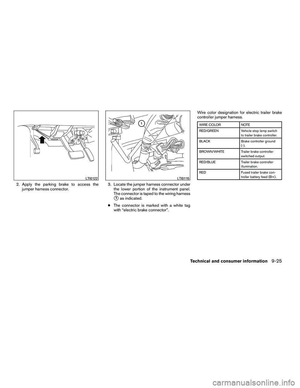
2. Apply the parking brake to access thejumper harness connector. 3. Locate the jumper harness connector under
the lower portion of the instrument panel.
The connector is taped to the wiring harness
�1as indicated.
● The connector is marked with a white tag
with “electric brake connector”. Wire color designation for electric trailer brake
controller jumper harness.