Page 153 of 438
●Closely supervise children when they
are around cars to prevent them from
playing and becoming locked in the
trunk where they could be seriously in-
jured. Keep the car locked, with the rear
seatback and trunk lid securely latched
when not in use, and prevent children’s
access to car keys.
To open the trunk lid, push the opener switch
down.
To close the trunk lid, lower and push the trunk lid
down securely.
NOTE:
You can open the trunk lid with the Intelli-
gent Key. Refer to “NISSAN Intelligent
Key™” in this section.
Cancel switch
When the switch, located inside the glove box, is
in the OFF position, the power to the trunk lid will
be cancelled. The trunk can only be opened with
the master key or keyfob.
The trunk lid cannot be opened when: ● using the trunk lid release switch,
● the trunk open request switch (if so
equipped) is pushed, when the Intelligent
Key is in range of the vehicle or
● the HOLD button on the Intelligent Key is
pressed.
INTERIOR TRUNK LID RELEASE
Page 154 of 438
To open the trunk from the inside, pull the illumi-
nated release handle until the lock releases and
push up on the trunk lid. The release handle is
made of a material that glows in the dark after a
brief exposure to ambient light.
The handle is located inside the trunk compart-
ment on the interior of the trunk lid.
OPENER OPERATION
The fuel-filler door release is located on the floor
to the left of the driver’s seat. To open the fuel-
filler door, pull up the release. To lock, close the
fuel-filler door securely.FUEL-FILLER CAP
The fuel-filler cap is a ratcheting type. Turn the
cap counterclockwise to remove. To tighten, turn
the cap clockwise until ratcheting clicks are
heard.
For the Coupe model, put the fuel-filler cap on the
cap holder
�1while refueling.
For the Sedan model, loop the tether strap
around the hook
�1while refueling.
Page 305 of 438
WARNING
●Do not leave children or adults who
would normally require the assistance
of others alone in your vehicle. Pets
should also not be left alone. They
could accidentally injure themselves or
others through inadvertent operation of
the vehicle. Also, on hot, sunny days,
temperatures in a closed vehicle could
quickly become high enough to cause
severe or possibly fatal injuries to
people or animals.
● Closely supervise children when they
are around cars to prevent them from
playing and becoming locked in the
trunk where they could be seriously in-
jured. Keep the car locked, with the rear
seatback and trunk lid securely latched
when not in use, and prevent children’s
access to car keys.
EXHAUST GAS (carbon monoxide)
Page 310 of 438

WARNING
Do not operate the push-button ignition
switch while driving the vehicle except in
an emergency. (The engine will stop when
the ignition switch is pushed 3 consecu-
tive times in quick succession or the igni-
tion switch is pushed and held for more
than 2 seconds.) If the engine stops while
the vehicle is being driven, this could lead
to a crash and serious injury.When the ignition switch is pushed without de-
pressing the brake pedal (CVT) or the clutch
pedal (MT) , the ignition switch position will illu-
minate as follows:
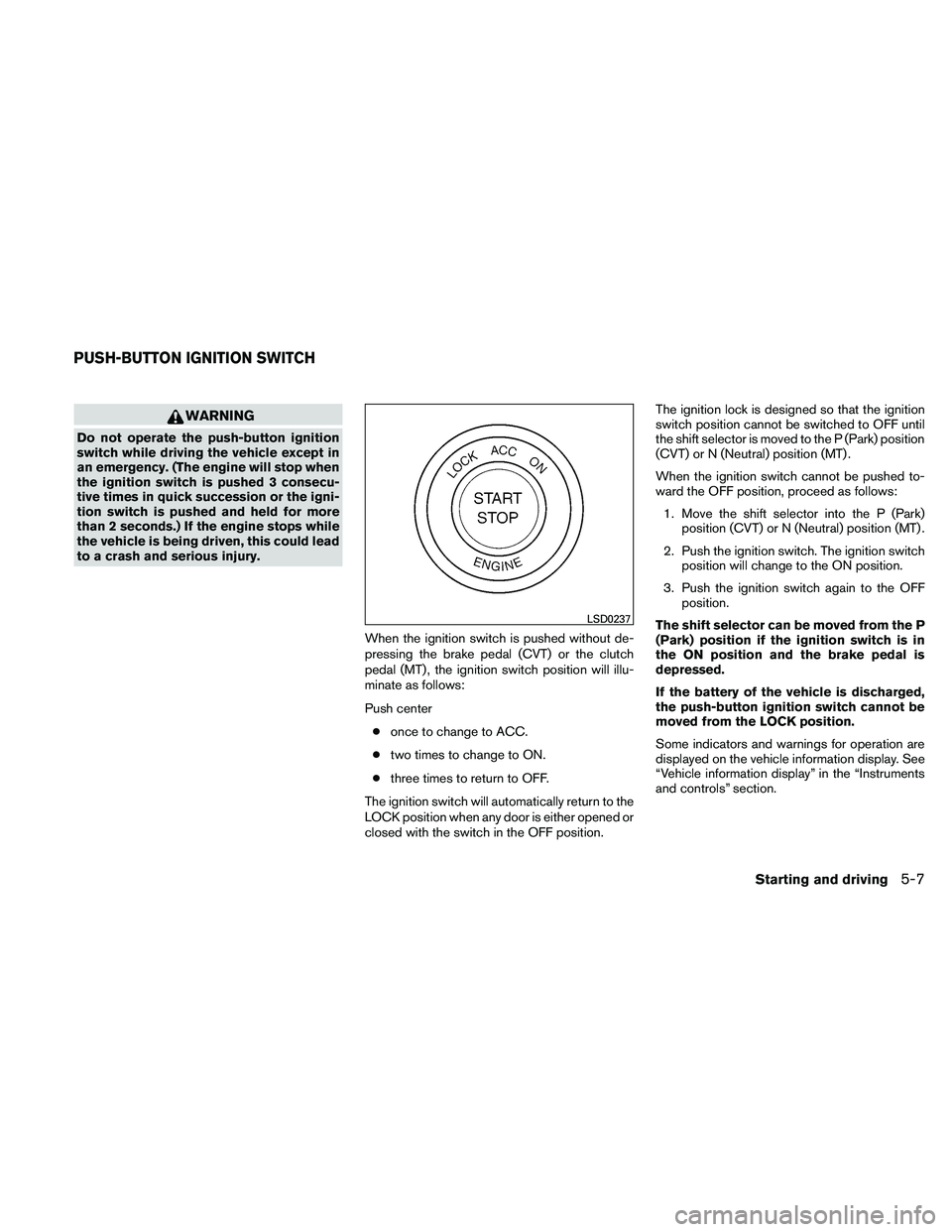
Push center● once to change to ACC.
● two times to change to ON.
● three times to return to OFF.
The ignition switch will automatically return to the
LOCK position when any door is either opened or
closed with the switch in the OFF position. The ignition lock is designed so that the ignition
switch position cannot be switched to OFF until
the shift selector is moved to the P (Park) position
(CVT) or N (Neutral) position (MT) .
When the ignition switch cannot be pushed to-
ward the OFF position, proceed as follows:
1. Move the shift selector into the P (Park) position (CVT) or N (Neutral) position (MT) .
2. Push the ignition switch. The ignition switch position will change to the ON position.
3. Push the ignition switch again to the OFF position.
The shift selector can be moved from the P
(Park) position if the ignition switch is in
the ON position and the brake pedal is
depressed.
If the battery of the vehicle is discharged,
the push-button ignition switch cannot be
moved from the LOCK position.
Some indicators and warnings for operation are
displayed on the vehicle information display. See
“Vehicle information display” in the “Instruments
and controls” section.
Page 334 of 438
WARNING
●Make sure the parking brake is securely
applied and the manual transmission is
shifted into R (Reverse) , or the CVT is
shifted into P (Park) .
● Never change tires when the vehicle is
on a slope, ice or slippery areas. This is
hazardous.
● Never change tires if oncoming traffic is
close to your vehicle. Wait for profes-
sional road assistance.
Blocking wheels
Place suitable blocks�1at both the front and
back of the wheel diagonally opposite the flat tire
�2to prevent the vehicle from moving when it is
jacked up.
Page 338 of 438

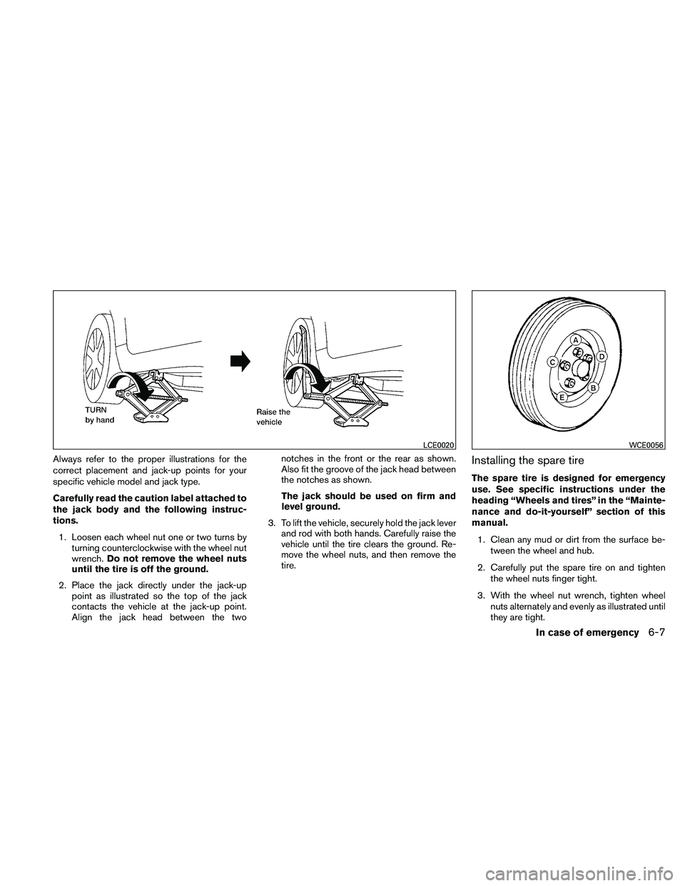
Always refer to the proper illustrations for the
correct placement and jack-up points for your
specific vehicle model and jack type.
Carefully read the caution label attached to
the jack body and the following instruc-
tions.1. Loosen each wheel nut one or two turns by turning counterclockwise with the wheel nut
wrench. Do not remove the wheel nuts
until the tire is off the ground.
2. Place the jack directly under the jack-up point as illustrated so the top of the jack
contacts the vehicle at the jack-up point.
Align the jack head between the two notches in the front or the rear as shown.
Also fit the groove of the jack head between
the notches as shown.
The jack should be used on firm and
level ground.
3. To lift the vehicle, securely hold the jack lever and rod with both hands. Carefully raise the
vehicle until the tire clears the ground. Re-
move the wheel nuts, and then remove the
tire.Installing the spare tire
The spare tire is designed for emergency
use. See specific instructions under the
heading “Wheels and tires” in the “Mainte-
nance and do-it-yourself” section of this
manual.
1. Clean any mud or dirt from the surface be- tween the wheel and hub.
2. Carefully put the spare tire on and tighten the wheel nuts finger tight.
3. With the wheel nut wrench, tighten wheel nuts alternately and evenly as illustrated until
they are tight.
Page 339 of 438
4. Lower the vehicle slowly until the tiretouches the ground. Then, with the wheel
nut wrench, tighten the wheel nuts securely
in the sequence illustrated (
�A,�B,�C,�D,
�E) . Lower the vehicle completely.
Page 344 of 438

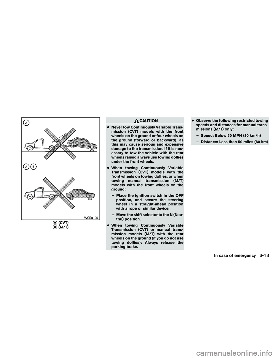
CAUTION
●Never tow Continuously Variable Trans-
mission (CVT) models with the front
wheels on the ground or four wheels on
the ground (forward or backward) , as
this may cause serious and expensive
damage to the transmission. If it is nec-
essary to tow the vehicle with the rear
wheels raised always use towing dollies
under the front wheels.
● When towing Continuously Variable
Transmission (CVT) models with the
front wheels on towing dollies, or when
towing manual transmission (M/T)
models with the front wheels on the
ground:
– Place the ignition switch in the OFF position, and secure the steering
wheel in a straight-ahead position
with a rope or similar device.
– Move the shift selector to the N (Neu- tral) position.
● When towing Continuously Variable
Transmission (CVT) or manual trans-
mission models (M/T) with the rear
wheels on the ground (if you do not use
towing dollies): Always release the
parking brake. ●
Observe the following restricted towing
speeds and distances for manual trans-
missions (M/T) only:
– Speed: Below 50 MPH (80 km/h)
– Distance: Less than 50 miles (80 km)