2010 NISSAN 370Z COUPE steering
[x] Cancel search: steeringPage 280 of 409
Black plate (280,1)
Model "Z34-D" EDITED: 2009/ 9/ 10
significantly more likely to be injured or
killed than a person properly wearing a
seat belt.OFF-ROAD RECOVERYWhile driving, the right side or left side wheels
may unintentionally leave the road surface. If this
occurs, maintain control of the vehicle by
following the procedure below. Please note that
this procedure is only a general guide. The
vehicle must be driven as appropriate based on
the conditions of the vehicle, road and traffic.
1. Remain calm and do not overreact.
2. Do not apply the brakes.
3. Maintain a firm grip on the steering wheelwith both hands and try to hold a straight
course.
4. When appropriate, slowly release the accel- erator pedal to gradually slow the vehicle.
5. If there is nothing in the way, steer the vehicle to follow the road while the vehicle
speed is reduced. Do not attempt to drive
the vehicle back onto the road surface until
vehicle speed is reduced.
6. When it is safe to do so, gradually turn the steering wheel until both tires return to the
road surface. When all tires are on the road
surface, steer the vehicle to stay in the appropriate driving lane.
.
If you decide that it is not safe to return
the vehicle to the road surface based on
vehicle, road or traffic conditions, gra-
dually slow the vehicle to a stop in a safe
place off the road.
RAPID AIR PRESSURE LOSSRapid air pressure loss or a “blow-out” can
occur if the tire is punctured or is damaged due
to hitting a curb or pothole. Rapid air pressure
loss can also be caused by driving on under-
inflated tires.
Rapid air pressure loss can affect the handling
and stability of the vehicle, especially at highway
speeds.
Help prevent rapid air pressure loss by main-
taining the correct air pressure and visually
inspect the tires for wear and damage. See
“WHEELS AND TIRES” in the “8. Maintenance
and do-it-yourself” section of this manual.
If a tire rapidly loses air pressure or “blows-out”
while driving maintain control of the vehicle by
following the procedure below. Please note that
this procedure is only a general guide. The
vehicle must be driven as appropriate based on
the conditions of the vehicle, road and traffic.
WARNING
The following actions can increase the
chance of losing control of the vehicle if
there is a sudden loss of tire air
pressure. Losing control of the vehicle
may cause a collision and result in
personal injury.
. The vehicle generally moves or pulls
in the direction of the flat tire.
. Do not rapidly apply the brakes.
. Do not rapidly release the accelera-
tor pedal.
. Do not rapidly turn the steering
wheel.
1. Remain calm and do not overreact.
2. Maintain a firm grip on the steering wheel with both hands and try to hold a straight
course.
3. When appropriate, slowly release the accel- erator pedal to gradually slow the vehicle.
4. Gradually steer the vehicle to a safe location off the road and away from traffic if possible.
5. Lightly apply the brake pedal to gradually stop the vehicle.
5-6
Starting and driving
Page 283 of 409
Black plate (283,1)
Model "Z34-D" EDITED: 2009/ 9/ 10
during the OFF position.
The ignition switch is equipped with an anti-theft
steering lock device.
In order for the steering wheel to be locked, it
must be turned about 1/8 of a right or left turn
from the straight up position.
To lock the steering wheel, push the
ignition switch to the OFF position. To
unlock the steering wheel, push the igni-
tion switch. If the steering lock release
malfunction indicator appears on the ve-
hicle information display, push the push-
button ignition switch again while lightly
turning the steering wheel right and left.
(See “VEHICLE INFORMATION DISPLAY”
in the “2. Instruments and controls” sec-
tion.)
If the battery of the vehicle is discharged,
the push-button ignition switch cannot be
turned from the LOCK position.
Some indicators and warnings for operation are
displayed on the vehicle information display.
(See “VEHICLE INFORMATION DISPLAY” in
the “2. Instruments and controls” section.)
Automatic transmission modelsThe ignition lock is designed so that the ignition
switch position cannot be switched to LOCK
until the selector lever is moved to the P (Park) position.
When the ignition switch cannot be pushed
toward the LOCK position, proceed as follows:
1. Move the selector lever into the P (Park)
position.
2. Push the ignition switch to the OFF position. The ignition switch position indicator will not
illuminate.
3. Open the door. The ignition switch will change to the LOCK position.
The selector lever can be moved from the P
(Park) position if the ignition switch is in
the ON position and the brake pedal is
depressed.
PUSH-BUTTON IGNITION SWITCH
POSITIONS
LOCK (Normal parking position)The ignition switch can only be locked in this
position.
The ignition switch will be unlocked when it is
pushed to the ACC position while carrying the
Intelligent Key or with the Intelligent Key inserted
in the port.ACC (Accessories)This position activates electrical accessories
such as the radio, when the engine is not running.
ON (Normal operating position)This position turns on the ignition system and
electrical accessories.OFFThe engine can be turned off without locking the
steering wheel.
Automatic transmission models: The ignition
lock is designed so that the ignition switch
cannot be switched to the LOCK position until
the selector lever is moved to the P (Park)
position.
CAUTION
Do not leave the vehicle with the push-
button ignition switch in ACC or ON
positions when the engine is not run-
ning for an extended period. This can
discharge the battery.
Starting and driving
5-9
Page 289 of 409
Black plate (289,1)
Model "Z34-D" EDITED: 2009/ 9/ 10
Accelerator downshift
— In D (Drive) position —For passing or hill climbing, fully depress the
accelerator pedal to the floor. This shifts the
transmission down into the lower gear, depend-
ing on the vehicle speed.Fail-safeWhen the fail-safe operation occurs, note that
the transmission will be locked in any of the
forward gears according to the condition.
If the vehicle is driven under extreme
conditions, such as excessive wheel spin-
ning and subsequent hard braking, the
fail-safe system may be activated. This will
occur even if all electrical circuits are
functioning properly. In this case, push
the ignition switch to the OFF position and
wait for 3 seconds. Then push the ignition
switch back to the ON position. The vehicle
should return to its normal operating
condition. If it does not return to its normal
operating condition, have a NISSAN dealer
check the transmission and repair if ne-
cessary.
SSD0829
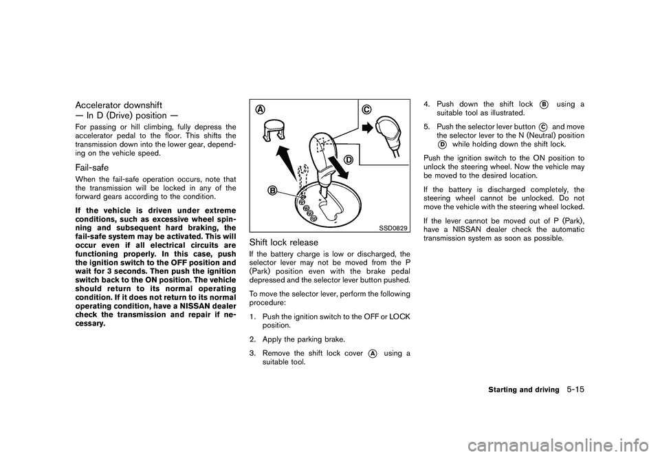
Shift lock releaseIf the battery charge is low or discharged, the
selector lever may not be moved from the P
(Park) position even with the brake pedal
depressed and the selector lever button pushed.
To move the selector lever, perform the following
procedure:
1. Push the ignition switch to the OFF or LOCKposition.
2. Apply the parking brake.
3. Remove the shift lock cover
*A
using a
suitable tool. 4. Push down the shift lock
*B
using a
suitable tool as illustrated.
5. Push the selector lever button
*C
and move
the selector lever to the N (Neutral) position
*D
while holding down the shift lock.
Push the ignition switch to the ON position to
unlock the steering wheel. Now the vehicle may
be moved to the desired location.
If the battery is discharged completely, the
steering wheel cannot be unlocked. Do not
move the vehicle with the steering wheel locked.
If the lever cannot be moved out of P (Park) ,
have a NISSAN dealer check the automatic
transmission system as soon as possible.
Starting and driving
5-15
Page 298 of 409
Black plate (298,1)
Model "Z34-D" EDITED: 2009/ 9/ 10
cannot be moved without depres-
sing the foot brake pedal.
1. Firmly apply the parking brake.
2. Automatic transmission models:
Move the selector lever to the P (Park)
position.
Manual transmission models:
Place the shift lever in the R (Reverse) gear.
When parking on an uphill grade, place the
shift lever in the 1st gear.
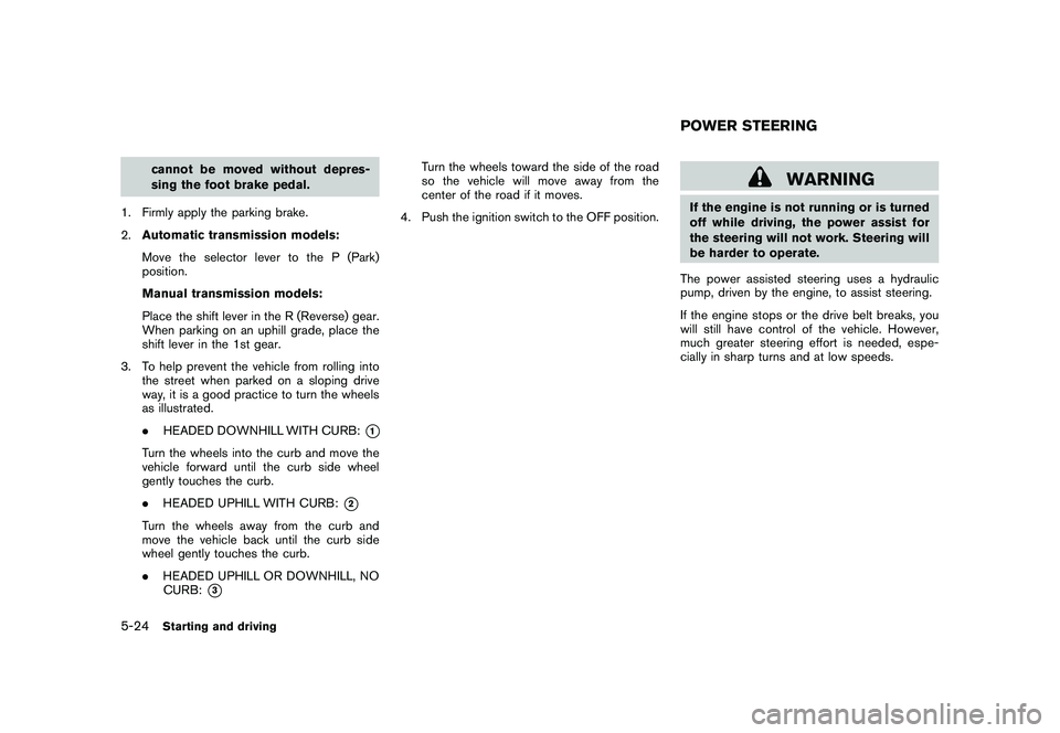
3. To help prevent the vehicle from rolling into the street when parked on a sloping drive
way, it is a good practice to turn the wheels
as illustrated.
.HEADED DOWNHILL WITH CURB:
*1
Turn the wheels into the curb and move the
vehicle forward until the curb side wheel
gently touches the curb.
.HEADED UPHILL WITH CURB:
*2
Turn the wheels away from the curb and
move the vehicle back until the curb side
wheel gently touches the curb.
.HEADED UPHILL OR DOWNHILL, NO
CURB:
*3
Turn the wheels toward the side of the road
so the vehicle will move away from the
center of the road if it moves.
4. Push the ignition switch to the OFF position.
WARNING
If the engine is not running or is turned
off while driving, the power assist for
the steering will not work. Steering will
be harder to operate.
The power assisted steering uses a hydraulic
pump, driven by the engine, to assist steering.
If the engine stops or the drive belt breaks, you
will still have control of the vehicle. However,
much greater steering effort is needed, espe-
cially in sharp turns and at low speeds.POWER STEERING
5-24
Starting and driving
Page 300 of 409

Black plate (300,1)
Model "Z34-D" EDITED: 2009/ 9/ 10
BRAKE ASSISTWhen the force applied to the brake pedal
exceeds a certain level, the Brake Assist is
activated generating greater braking force than a
conventional brake booster even with light pedal
force.
WARNING
The Brake Assist is only an aid to assist
braking operation and is not a collision
warning or avoidance device. It is the
driver’s responsibility to stay alert, drive
safely and be in control of the vehicle at
all times.ANTI-LOCK BRAKING SYSTEM (ABS)
WARNING
.The Anti-lock Braking System (ABS)
is a sophisticated device, but it
cannot prevent accidents resulting
from careless or dangerous driving
techniques. It can help maintain
vehicle control during braking on
slippery surfaces. Remember that
stopping distances on slippery sur-
faces will be longer than on normal
surfaces even with ABS. Stopping distances may also be longer on
rough, gravel or snow covered
roads, or if you are using tire chains.
Alwaysmaintainasafedistance
from the vehicle in front of you.
Ultimately, the driver is responsible
for safety.
. Tire type and condition may also
affect braking effectiveness.
— When replacing tires, install the
specified size of tires on all four
wheels.
— When installing a spare tire, make sure that it is the proper
size and type as specified on the
Tire and Loading Information
label. See “TIRE AND LOADING
INFORMATION LABEL” in the “9.
Technical and consumer infor-
mation” section of this manual.
— For detailed information, see “WHEELS AND TIRES” in the
“8. Maintenance and do-it-your-
self” section of this manual.
The Anti-lock Braking System (ABS) controls
the brakes so the wheels do not lock during hard
braking or when braking on slippery surfaces.
The system detects the rotation speed at each wheel and varies the brake fluid pressure to
prevent each wheel from locking and sliding. By
preventing each wheel from locking, the system
helps the driver maintain steering control and
helps to minimize swerving and spinning on
slippery surfaces.
Using the systemDepress the brake pedal and hold it down.
Depress the brake pedal with firm steady
pressure, but do not pump the brakes. The
ABS will operate to prevent the wheels from
locking up. Steer the vehicle to avoid obstacles.
WARNING
Do not pump the brake pedal. Doing so
may result in increased stopping dis-
tances.Self-test featureThe ABS includes electronic sensors, electric
pumps, hydraulic solenoids and a computer. The
computer has a built-in diagnostic feature that
tests the system each time you start the engine
and move the vehicle at a low speed in forward
or reverse. When the self-test occurs, you may
hear a “clunk” noise and/or feel a pulsation in the
brake pedal. This is normal and does not
indicate a malfunction. If the computer senses
a malfunction, it switches the ABS off and
illuminates the ABS warning light on the
BRAKE ASSIST5-26
Starting and driving
Page 301 of 409

Black plate (301,1)
Model "Z34-D" EDITED: 2009/ 9/ 10
instrument panel. The brake system then oper-
ates normally, but without anti-lock assistance.
If the ABS warning light illuminates during the
self-test or while driving, have the vehicle
checked by a NISSAN dealer.Normal operationThe ABS operates at speeds above 3 to 6 MPH
(5 to 10 km/h) .
When the ABS senses that one or more wheels
are close to locking up, the actuator rapidly
applies and releases hydraulic pressure. This
action is similar to pumping the brakes very
quickly. You may feel a pulsation in the brake
pedal and hear a noise from under the hood or
feel a vibration from the actuator when it is
operating. This is normal and indicates that the
ABS is operating properly. However, the pulsa-
tion may indicate that road conditions are
hazardous and extra care is required while
driving.The Vehicle Dynamic Control (VDC) system
uses various sensors to monitor driver inputs
and vehicle motion. Under certain driving con-
ditions, the VDC system helps to perform the
following functions.
.
Controls brake pressure to reduce wheel
slip on one slipping drive wheel so power is
transferred to a non slipping drive wheel on
the same axle.
. Controls brake pressure and engine output
to reduce drive wheel slip based on vehicle
speed (traction control function) .
. Controls brake pressure at individual wheels
and engine output to help the driver maintain
control of the vehicle in the following
conditions:
— understeer (vehicle tends to not follow the steered path despite increased steering
input)
— oversteer (vehicle tends to spin due to certain road or driving conditions) .
The VDC system can help the driver to maintain
control of the vehicle, but it cannot prevent loss
of vehicle control in all driving situations.
When the VDC system operates, the
indicator in the instrument panel flashes so note
the following:
. The road may be slippery or the system may determine some action is required to help
keep the vehicle on the steered path.
. You may feel a pulsation in the brake pedal
and hear a noise or vibration from under the
hood. This is normal and indicates that the
VDC system is working properly.
. Adjust your speed and driving to the road
conditions.
See “Slip indicator light” in the “2. Instruments
and controls” section and “Vehicle Dynamic
Control (VDC) off indicator light” in the “2.
Instruments and controls” section.
If a malfunction occurs in the system, the
and
indicatorlightscomeoninthe
instrument panel. The VDC system automatically
turns off when these indicator lights are on.
The VDC OFF switch is used to turn off the VDC
system. The VDC off indicator illuminates to
indicate the VDC system is off. When the VDC
switch is used to turn off the system, the VDC
system still operates to prevent one drive wheel
from slipping by transferring power to a non
slipping drive wheel. The
indicator flashes
if this occurs. All other VDC functions are off and
the
indicator will not flash. The VDC
System is automatically reset to on when the
ignition switch is placed in the off position then
back to the on position.
The computer has a built-in diagnostic feature
VEHICLE DYNAMIC CONTROL (VDC)
SYSTEM
Starting and driving
5-27
Page 302 of 409
Black plate (302,1)
Model "Z34-D" EDITED: 2009/ 9/ 10
that tests the system each time you start the
engine and move the vehicle forward or in
reverse at a slow speed. When the self-test
occurs, you may hear a “clunk” noise and/or feel
a pulsation in the brake pedal. This is normal and
is not an indication of a malfunction.
WARNING
.The VDC system is designed to help
the driver maintain stability but
does not prevent accidents due to
abrupt steering operation at high
speeds or by careless or dangerous
driving techniques. Reduce vehicle
speed and be especially careful
when driving and cornering on slip-
pery surfaces and always drive care-
fully.
. Do not modify the vehicle’s suspen-
sion. If suspension parts such as
shock absorbers, struts, springs,
stabilizer bars, bushings and
wheels are not NISSAN recom-
mended for your vehicle or are
extremely deteriorated the VDC sys-
tem may not operate properly. This
could adversely affect vehicle hand-
ling performance, and the
in-
dicator may flash or bothand
indicator lights may illuminate.
. If brake related parts such as brake
pads, rotors and calipers are not
NISSAN recommended or are extre-
mely deteriorated, the VDC system
may not operate properly and bothand
indicator lights may
illuminate.
. If engine control related parts are
not NISSAN recommended or are
extremely deteriorated, both the
and
indicator lights may
illuminate.
. When driving on extremely inclined
surfaces such as higher banked
corners, the VDC system may not
operate properly and the
in-
dicator may flash or bothand
indicator lights may illuminate.
Do not drive on these types of
roads.
. When driving on an unstable sur-
face such as a turntable, ferry,
elevator or ramp, the
indicator
may flash or bothand
indicator lights may illuminate. This
is not a malfunction. Restart the
engine after driving onto a stable surface.
. If wheels or tires other than the
NISSAN recommended ones are
used, the VDC system may not
operate properly and the
in-
dicator may flash or bothand
indicator lights may illuminate.
. The VDC system is not a substitute
for winter tires or tire chains on a
snow covered road.
5-28
Starting and driving
Page 305 of 409
Black plate (305,1)
Model "Z34-D" EDITED: 2009/ 9/ 10
.Watch for slippery spots (glare ice) .
These may appear on an otherwise
clear road in shaded areas. If a
patch of ice is seen ahead, brake
before reaching it. Try not to brake
while on the ice, and avoid any
sudden steering maneuvers.
. Do not use the cruise control on
slippery roads.
. Snow can trap dangerous exhaust
gases under your vehicle. Keep
snow clear of the exhaust pipe and
from around your vehicle.
ENGINE BLOCK HEATER (if so
equipped)Engine block heaters are used to assist with
cold temperature starting.
The engine block heater should be used when
the outside temperature is 20 8F( �7 8C) or lower.To use the engine block heater1. Turn the engine off.
2. Open the hood and unwrap the engine
block heater cord.
3. Plug the engine block heater cord into a grounded 3-wire, 3-pronged extension cord.
4. Plug the extension cord into a Ground Fault Interrupt (GFI) protected, grounded 110-
volt AC (VAC) outlet.
5. The engine block heater must be plugged in for at least 2 - 4 hours, depending on
outside temperatures, to properly warm the
engine coolant. Use an appropriate timer to
turn the engine block heater on.
6. Before starting the engine, unplug and properly store the cord to keep it away from
moving parts.
WARNING
.Do not use your engine block heater
with an ungrounded electrical sys-
tem or a 2-pronged adapter. You can
be seriously injured by an electrical
shock if you use an ungrounded
connection.
. Disconnect and properly store the
engine block heater cord before
starting the engine. Damage to the
cord could result in an electrical
shock and can cause serious injury.
. Use a heavy-duty 3-wire, 3-pronged
extension cord rated for at least
10A. Plug the extension cord into a
Ground Fault Interrupt (GFI) pro-
tected, grounded 110-VAC outlet.
Failure to use the proper extension
cord or a grounded outlet can result
in a fire or electrical shock and
cause serious personal injury.
Starting and driving
5-31