Page 550 of 658
Vehicle care and maintenance
7-19
7 Rear axle oil (All-wheel drive models)
N00915200201
Whenever the oil level is checked, add oil as necessary to
maintain the proper level.
Fill or change oil according to the table.Oil type
AW C c o n t r o l f l u i d
(if so equipped)
N00915300042
To check the fluid levelThe AWC control fluid reservoir is in the luggage compart-
ment.NOTE�
Check the fluid level in the reservoir 90 minutes or more
after turning the ignition switch to the “LOCK” position.
1. Remove the lid of the cargo floor box (A) on the right
side.
Lubricant DiaQueen LSD gear oil or equivalent
BK0103001US.book 19 ページ 2009年8月20日 木曜日 午前10時45分
Page 554 of 658
Vehicle care and maintenance
7-23
7 Battery
N00939100826
The condition of the battery is very important for quick starting
and to keep the vehicle’s electrical system working properly.
Check the battery regularly. Removing and installing the battery upper cover
(vehicles equipped with turbocharger)
N00901300025
To r e m o v e1. Remove the two clips (A), and then remove the air duct
(B).
WA R N I N G
!�
An SRS airbag sensor is located in the front of the
engine compartment near the battery.
When checking or replacing the battery, or when
working around this area, do not strike or damage
this sensor.WA R N I N G
!�
Turn the ignition switch to the “LOCK” position on
vehicle. Make sure that your clothes cannot be
caught by the fan or drive belt. Personal injury
could result.
BK0103001US.book 23 ページ 2009年8月20日 木曜日 午前10時45分
Page 574 of 658

Vehicle care and maintenance
7-43
7
Fuel hoses
N00941000037
Check the hose surfaces for any heat and mechanical damage,
hard and brittle rubber, cracking, tears, cuts and abrasions. Pay
special attention to the hoses closest to high heat sources such
as the exhaust manifold. Check all the hose connections, such
as clamps and couplings, to make sure they are secure and that
there are no leaks. If you see any wear or damage, replace the
hoses immediately.Ignition cables
N00941100041
The ignition cables should be kept clean, properly connected,
and fully seated. Terminals should be fully seated and the nip-
ple assemblies should not be removed from the coil towers
unless the nipples are damaged or cable testing indicates high
resistance or broken insulation. Cracked or damaged cables
must be replaced.Intake valve clearance
N00950100050
Have the valve clearance checked at an authorized Mitsubishi
Motors dealer at the mileage specified in the “WARRANTY
AND MAINTENANCE MANUAL”.
If the engine sounds abnormally loud, have adjustments made
by an authorized Mitsubishi Motors dealer.
Fuel system (tank, pipe line and connection, and
fuel tank filler cap)
N00941300186
Check these regularly for damage or leaks in the fuel lines and
connections. Check the fuel tank filler cap for damage or loose-
ness. Pay special attention to the fuel lines closest to high heat
sources such as the exhaust manifold.Evaporative emission control system (except
evaporative emission canister)
N00941400116
If the fuel-vapor vent line is clogged or damaged, the fuel-
vapor mixture will escape, polluting the air.
Have the system checked at an authorized Mitsubishi Motors
dealer at the mileage specified in the “WARRANTY AND
MAINTENANCE MANUAL”.
WA R N I N G
!�
If you see a fuel leak or if you smell fuel, do not run
the engine. Any spark (including from the ignition),
flame or smoking material could cause an explosion
or fire. Call an authorized Mitsubishi Motors dealer
or a repair facility of your choice for assistance.
BK0103001US.book 43 ページ 2009年8月20日 木曜日 午前10時45分
Page 583 of 658
7-52 Vehicle care and maintenance
7
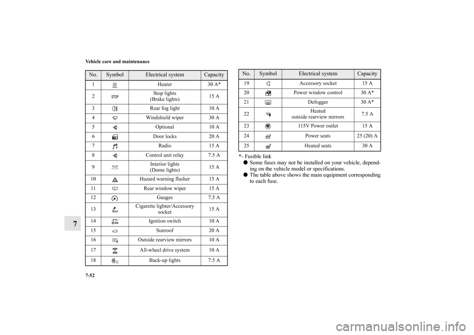
*- Fusible link�
Some fuses may not be installed on your vehicle, depend-
ing on the vehicle model or specifications.
�
The table above shows the main equipment corresponding
to each fuse.
No.
Symbol
Electrical system
Capacity
1 Heater 30 A*
2Stop lights
(Brake lights)15 A
3 Rear fog light 10 A
4 Windshield wiper 30 A
5 Optional 10 A
6 Door locks 20 A
7Radio15 A
8 Control unit relay 7.5 A
9Interior lights
(Dome lights)15 A
10 Hazard warning flasher 15 A
11 Rear window wiper 15 A
12 Gauges 7.5 A
13Cigarette lighter/Accessory
socket15 A
14 Ignition switch 10 A
15 Sunroof 20 A
16 Outside rearview mirrors 10 A
17 All-wheel drive system 10 A
18 Back-up lights 7.5 A
19 Accessory socket 15 A
20 Power window control 30 A*
21 Defogger 30 A*
22Heated
outside rearview mirrors7.5 A
23 115V Power outlet 15 A
24 Power seats 25 (20) A
25 Heated seats 30 ANo.
Symbol
Electrical system
Capacity
BK0103001US.book 52 ページ 2009年8月20日 木曜日 午前10時45分
Page 585 of 658

7-54 Vehicle care and maintenance
7
�
Some fuses may not be installed on your vehicle, depend-
ing on the vehicle model or specifications.
�
The table above shows the main equipment corresponding
to each fuse.
There are no 7.5 A, 25 A or 30 A spare fuses. If a fuse of one of
these capacities blows, replace it temporarily by borrowing one
of the fuses indicated below.
7.5 A: 10 A spare fuse
25 A: 20 A spare fuse
30 A: 30 A audio amplifier fuse
Replace the borrowed fuse with a fuse that has the correct
capacity as soon as possible.
17Headlight
(low/high beam) (right)20 A
*3
18Headlight
(low beam) (left)10 A
*4
19Headlight
(low beam) (right)10 A
*4
20
*1
ENG/POWER
10 A
*2
I/C SPRAY
21 Ignition coil 10 A
22
*1
ENG/POWER 20 A
Fuel line heater 25 A
22
*2
ENG/POWER 20 A
23 Fuel pump15 A
*1
20 A
*2
24 Starter
30 A
*5
25 — — —
26 Anti-lock braking system
40 A
*5
27 Anti-lock braking system
30 A
*5
28Air conditioning condenser fan
motor30 A
*5
29 Radiator fan motor
40 A
*5
No.
Symbol
Electrical system
Capacity
30 IOD IOD 30 A
31 Audio amplifier 30 A
32 Diesel 30 A
33 — Spare fuse 10 A
34 — Spare fuse 15 A
35 — Spare fuse 20 A
*1- Except for vehicles equipped with turbocharger
*2- Vehicles equipped with turbocharger
*3- For vehicles equipped with high intensity discharge head-
lights
*4- For vehicles without high intensity discharge headlights
*5- Fusible linkNo.
Symbol
Electrical system
Capacity
BK0103001US.book 54 ページ 2009年8月20日 木曜日 午前10時45分
Page 586 of 658
Vehicle care and maintenance
7-55
7
Identification of fuse
Fuse replacement
N00954900085
1. Before replacing a fuse, always turn off the electrical item
connected to the fuse and turn the ignition switch to the
“LOCK” position.
2. There is a fuse puller (A) in the engine compartment fuse
block.
Capacity
Color
7.5 A Brown
10 A Red
15 A Blue
20 A Yellow
25 A Natural (White)
30 A Green (fuse type)/Pink (fusible link type)
40 A Green
BK0103001US.book 55 ページ 2009年8月20日 木曜日 午前10時45分
Page 645 of 658

9-8 Specifications
9Engine specifications
N01147700370
NOTE�
At high altitude locations, the idle speed may be higher than the idle speed described in the vehicle emission control informa-
tion label. This is done in order to stabilize the idle speed when the power steering system and other systems operate. It does
not indicate a malfunction.
Item
2.0 liter
2.4 liter
Engine model 4B11 4B12Engine displacement 121.9 CID (1,998 cm³) 144.0 CID (2,360 cm³)No. of cylinders and cylinder arrangement 4 in-lineBore 3.39 in (86.0 mm) 3.46 in (88.0 mm)Stroke 3.39 in (86.0 mm) 3.82 in (97.0 mm)Compression ratio 9.0 10.5Thermostat valve opening temperature 170 °F (76.5 °C), 180 °F (82.0 °C) 180 °F (82.0 °C)Spark plugs
NGK ILKR7E6 FR5EIDENSO — K16PSR-B8
Spark plug gap .020 to .023 in (0.5 to 0.6 mm) .028 to .031 in (0.7 to 0.8 mm)Firing order 1-3-4-2Ignition timing, idle speed, mixture Refer to the “Vehicle emission control information label” inside panel of the engine hood.BK0103001US.book 8 ページ 2009年8月20日 木曜日 午前10時45分
Page 653 of 658

Alphabetical index
4
H
Handling of compact discs 5-94
Hands-free Bluetooth® cellular phone interface system with
voice recognition 3-242
Hazard warning flasher switch 3-229
Hazard warning lights 3-214
Head restraints 2-9
Headlight leveling switch 3-227
Headlights
Bulb capacity 7-58
Dimmer 3-224
Headlight flasher 3-225
Leveling switch 3-227
Replacement 7-61
,7-64
Switch 3-220
High beam indicator 3-214
High-mounted stop light 7-58
Hill start assist 3-132
Hood lock release mechanism and safety catch 7-46
Horn switch 3-241
I
If the vehicle breaks down 6-2
Ignition cables 7-43
Ignition switch 3-24
,3-81
Important facts to know in case of an accident 8-5
Indicators 3-214
Information screen display 3-217Inside day/night rearview mirror 3-77
Instrument cluster 3-160
Interior lights 3-279
J
Jack 6-8
Storage 6-7
Jump-starting the engine 6-2
K
Key reminder buzzer 3-55
Keyless entry system 3-8
Keys 3-2
L
Labeling 9-2
License plate light
Bulb capacity 7-58
Replacement 7-86
Limited-slip differential 3-130
Loading information 4-7
Lubricants 9-10
M
Malfunction indicator 3-215
Manual transaxle 3-90
Oil 7-17
,9-10
Shift points (recommended speed) 3-91
Mirror
BK0103001US.book 4 ページ 2009年8月20日 木曜日 午前10時45分

N00915200201
Whenever the oil level is checked, add oil as necessary to
maintain the proper level.
Fill or change oil accordi")