2010 MERCEDES-BENZ SLS COUPE flat tire
[x] Cancel search: flat tirePage 12 of 361
F
Fast forward/rewind ................176, 194
Faul tmessage
see Display message .....................289
Fire extinguisher ............................... 289
First-aid kit ......................................... 289
Flat tyre Equipment ..................................... 325
Preparing the vehicle .....................325
TIREFIT kit ...................................... 326
Floormat ............................................ .264
Folders Selecting (MP3 mode )................... 176
Fording ............................................... 278
Frequencies Telephone ...................................... 347
Frequency entry
Manual .......................................... .162
Front airbag ......................................... 38
Front-passenger airbag ....................... 38
Fron tpassenge rkneebag ................... 39
Fuel ..................................................... 349
Loss ............................................... 314
Petrol ............................................. 267
Fuel consumption
Current (on-board computer) .........233
Notes ............................................. 349
Fuel filler flap
Opening/closing ............................ 266
Fuel gauge ............................................ 25
Fuel level Calling up the range (on-board
computer) ...................................... 233
Gauge .............................................. 25
Fuel line
Malfunction ................................... .314
Fuel tank
Defect ............................................ 314
Function restrictions
Addres sbook ........................ 151, 154
Music Register ............................... 183
Using the telephone ....................... 128
Video DVD mode ........................... 191
Fuse allocation chart ........................342
Fuse box Front-passenger footwell ...............342
Rea r............................................... 342Fuses
.................................................. 342 G
Garage door Opening/closing (with the remote
control) .......................................... 263
Garage door opener ..........................262
Clearing the memory .....................264
Programming the remote control ...262
Gear indicator .................................... 227
Gearshift program SETUP (on-board computer) ..........241
Genuine parts .................................... 346
Glove compartment ..........................257
Locking and unlocking (sepa-
rately) ............................................ 257
Gracenote ®
Media Database ............177 H
Hands-free microphone Switching on/off ........................... 146
Headbag ............................................... 40
Headlamp cleaning system ..............270
Headlamps Cleaning ......................................... 283
Cleaning system ............................ 217
Misting up ...................................... 317
Heating
see Air conditioning
High-pressure cleaners ....................282
Hill start assist .................................. 221
Home address see My address
HomeLink ®
see Garage door opener
House number
Entering ........................................... 99 I
Ignition lock ............................... 203, 258
Immobiliser .......................................... 49
Indicator and warning lamps ...........308
Air conditioning (malfunction) ........307
Automatic child sea trecognition
(malfunction) ................................. 307
Engine diagnostics .........................310 Index
9 BA 197 ECE RE 2010/6a; 1; 2, en-GB
sabbae uV ersion: 3.0.3.6
2010-05-07T14:19:43+02:00 - Seite 9
Page 292 of 361
X
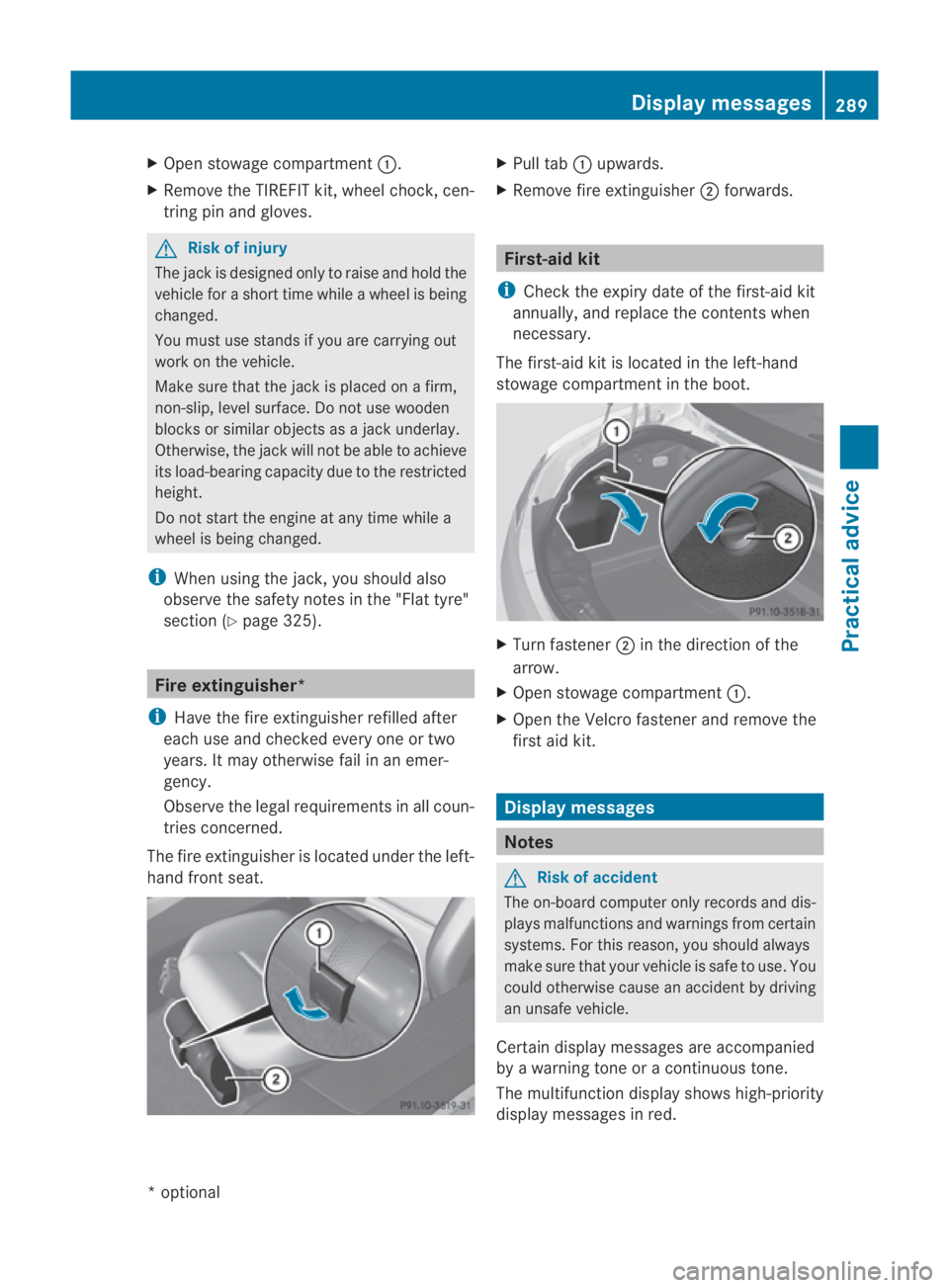
Open stowage compartment 0001.
X Remove the TIREFIT kit, wheel chock, cen-
tring pin and gloves. G
Risk of injury
The jack is designed only to raise and hold the
vehicle for a short time while a wheel is being
changed.
You must use stands if you are carrying out
work on the vehicle.
Make sure that the jack is placed on a firm,
non-slip, level surface. Do not use wooden
blocks or similaro bjects as a jack underlay.
Otherwise, the jack will not be able to achieve
its load-bearing capacity due to the restricted
height.
Do not start the engine at any time while a
wheel is being changed.
i When using the jack, you should also
observe the safety notes in the "Flat tyre"
section (Y page 325). Fire extinguisher*
i Have the fire extinguisher refilled after
each use and checked every one or two
years. It may otherwise fail in an emer-
gency.
Observe the legal requirements in all coun-
tries concerned.
The fire extinguisher is located under the left-
hand front seat. X
Pull tab 0001upwards.
X Remove fire extinguisher 0002forwards. First-aid kit
i Check the expiry date of the first-aid kit
annually, and replace the contents when
necessary.
The first-aid kit is located in the left-hand
stowage compartment in the boot. X
Turn fastener 0002in the direction of the
arrow.
X Open stowage compartment 0001.
X Open the Velcro fastener and remove the
first aid kit. Display messages
Notes
G
Risk of accident
The on-board computer only records and dis-
plays malfunctions and warnings from certain
systems .For this reason, you should always
make sure that your vehicle is safe to use. You
could otherwise cause an accident by driving
an unsafe vehicle.
Certain display messages are accompanied
by a warning tone or acontinuous tone.
The multifunction display shows high-priority
display messages in red. Display messages
289Practical advice
*optional
BA 197 ECE RE 2010/6a; 1; 2, en-GB
sabbaeu
Version: 3.0.3.6 2010-05-07T14:19:43+02:00 - Seite 289 Z
Page 328 of 361
Replacing the wiper blades
G
Ris
kofa ccident
The windscreen will no tlonger be wiped prop-
erly if the wiper blades are worn. This could
prevent you from observing the traffic condi-
tions, thereby causing an accident .Replace
the wiper blades twice a year, ideally in spring
and autumn. G
Risk of accident
The wiper arms could start moving and cause
an injury if you leave the windscreen wipers
switched on.
Remove the key from the ignition lock before
replacing the wiper blades.
! To avoid damaging the windscreen wiper
blades, make sure that you touch only the
wiper arm of the windscreen wiper. Removing
Moving the wiper blades to avertical
position X
Switch off the engine.
X Take your foo toff the brake pedal.
X Set the windscreen wipers to posi-
tion 0014 on the combination switch.
X Press the Start/Stop button repeatedly
until the windscreen wipers start.
X When the wiper arms have reached a ver-
tical position, press the Start/Stop button.
X Fold the wiper arm away from the wind-
screen until it engages.
X Set the wiper blade at right angles to the
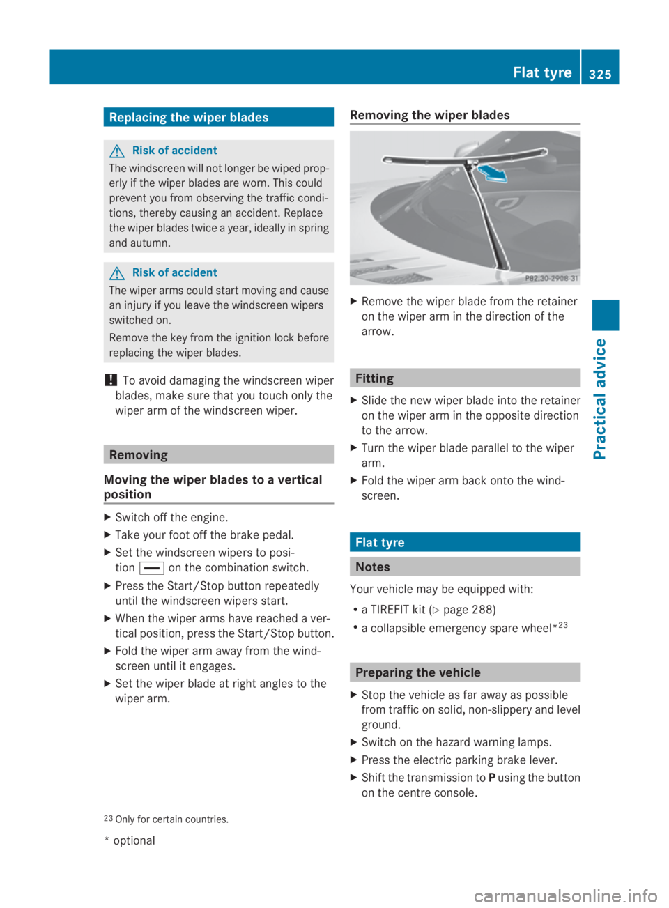
wiper arm. Removing the wiper blades X
Remove the wiper blade from the retainer
on the wiper arm in the direction of the
arrow. Fitting
X Slide the new wiper blade into the retainer
on the wiper arm in the opposite direction
to the arrow.
X Turn the wiper blade parallel to the wiper
arm.
X Fold the wiper arm back onto the wind-
screen. Flat tyre
Notes
You rvehicle may be equipped with:
R a TIREFIT kit (Y page 288)
R a collapsible emergency spare wheel* 23 Preparing the vehicle
X Stop the vehicle as far away as possible
from traffic on solid, non-slippery and level
ground.
X Switch on the hazard warning lamps.
X Press the electric parking brake lever.
X Shift the transmission to Pusing the button
on the centre console.
23 Only for certain countries. Flat tyre
325Practical advice
*optional
BA 197 ECE RE 2010/6a; 1; 2, en-GB
sabbaeu Version: 3.0.3.6 2010-05-07T14:19:43+02:00 - Seite 325 Z
Page 329 of 361
X
Get all occupants out of the vehicle .Make
sure that they are no tendangered as they
ge to ut of the vehicle.
X Make sure that no one is near the danger
area whils tawheel is being changed. Any-
one who is not directly assisting in the
wheel change should, for example, stand
behind the barrier.
X Switch off the engine.
X Remove the key from the ignition lock.
X Get out of the vehicle.
X Close the driver’s door.
X Place the warning triangle ( Ypage 288) at
a suitable distance. Observe legal require-
ments. Using the TIREFIT kit
You can use the TIREFI Tkit to seal small
punctures, particularly those in the tyre tread.
You can use TIREFIT at outside temperatures
down to -40 †. G
Risk of accident
In the following situations ,your safety is at
particular risk and tyre sealant is unable to
provide breakdown assistance if:
R there are cuts or punctures in the tyre
greater than 4 mm
R the wheel rim is damaged
R you have driven at very low tyre pressures
or on a flat tyre
Do not drive any further. Consult a qualified
specialist workshop which has the necessary
specialist knowledge and tools to carry out
the work required.
Mercedes-Benz recommends that you use a
Mercedes-Benz Service Centre for this pur-
pose. In particular, work relevant to safety or
on safety-related systems must be carried out
at a qualified specialist workshop. X
Do not remove any foreign objects which
have penetrated the tyre, e.g. screws or
nails.
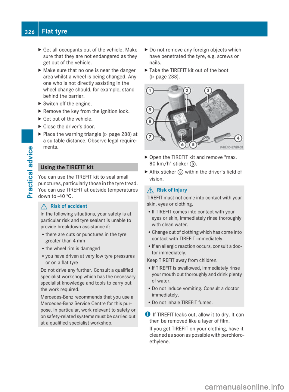
X Take the TIREFIT kit out of the boot
(Y page 288). X
Open the TIREFIT kit and remove "max.
80 km/h" sticker 000B.
X Affix sticker 000Bwithin the driver's field of
vision. G
Risk of injury
TIREFIT must not come into contact with your
skin, eyes or clothing.
R If TIREFIT comes into contact with your
eyes or skin, immediately rinse thoroughly
with clean water.
R Change out of clothing which has come into
contact with TIREFIT immediately.
R If an allergic reaction occurs, consult a doc-
tor immediately.
Keep TIREFIT away from children.
R If TIREFIT is swallowed, immediately rinse
your mouth out thoroughly and drink plenty
of water.
R Do not induce vomiting. Consult a doctor
immediately.
R Do not inhale TIREFIT fumes.
i If TIREFIT leaks out, allow it to dry. It can
then be removed like a layer of film.
If you get TIREFIT on your clothing, have it
cleaned as soon as possible with perchloro-
ethylene. 326
Flat tyrePractical advice
BA 197 ECE RE 2010/6a; 1; 2, en-GB
sabbaeu
Version: 3.0.3.6 2010-05-07T14:19:43+02:00 - Seite 326
Page 330 of 361
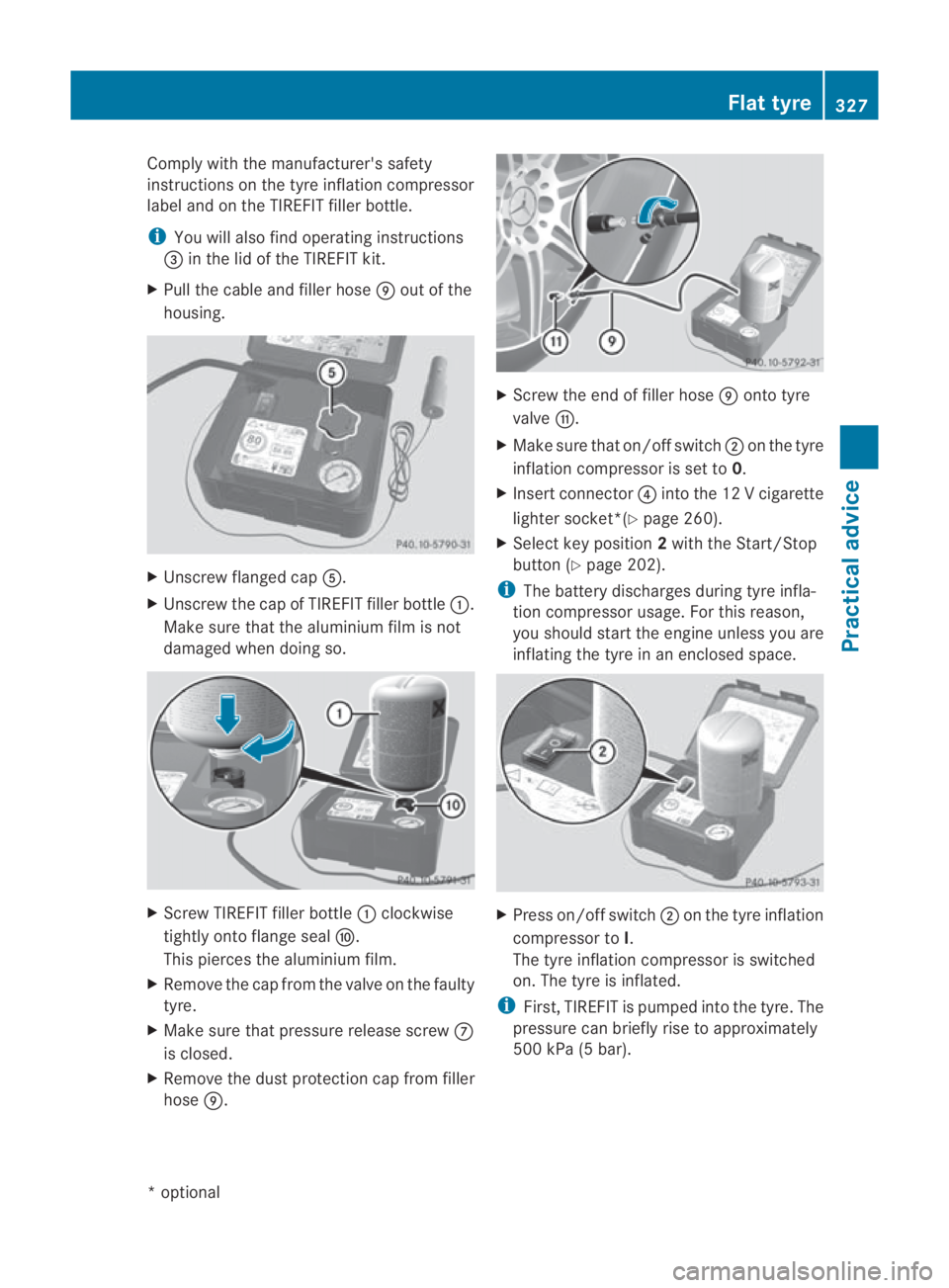
Comply with the manufacturer's safety
instructions on the tyr
einflatio ncompressor
label and on the TIREFIT filler bottle.
i You will also find operating instructions
0015 in the lid of the TIREFIT kit.
X Pull the cable and filler hose 000Cout of the
housing. X
Unscrew flanged cap 0012.
X Unscrew the cap of TIREFIT filler bottle 0001.
Make sure that the aluminium film is not
damaged when doing so. X
Screw TIREFIT filler bottle 0001clockwise
tightly onto flange seal 000D.
This pierces the aluminium film.
X Remove the cap from the valve on the faulty
tyre.
X Make sure that pressure release screw 000A
is closed.
X Remove the dust protection cap from filler
hose 000C. X
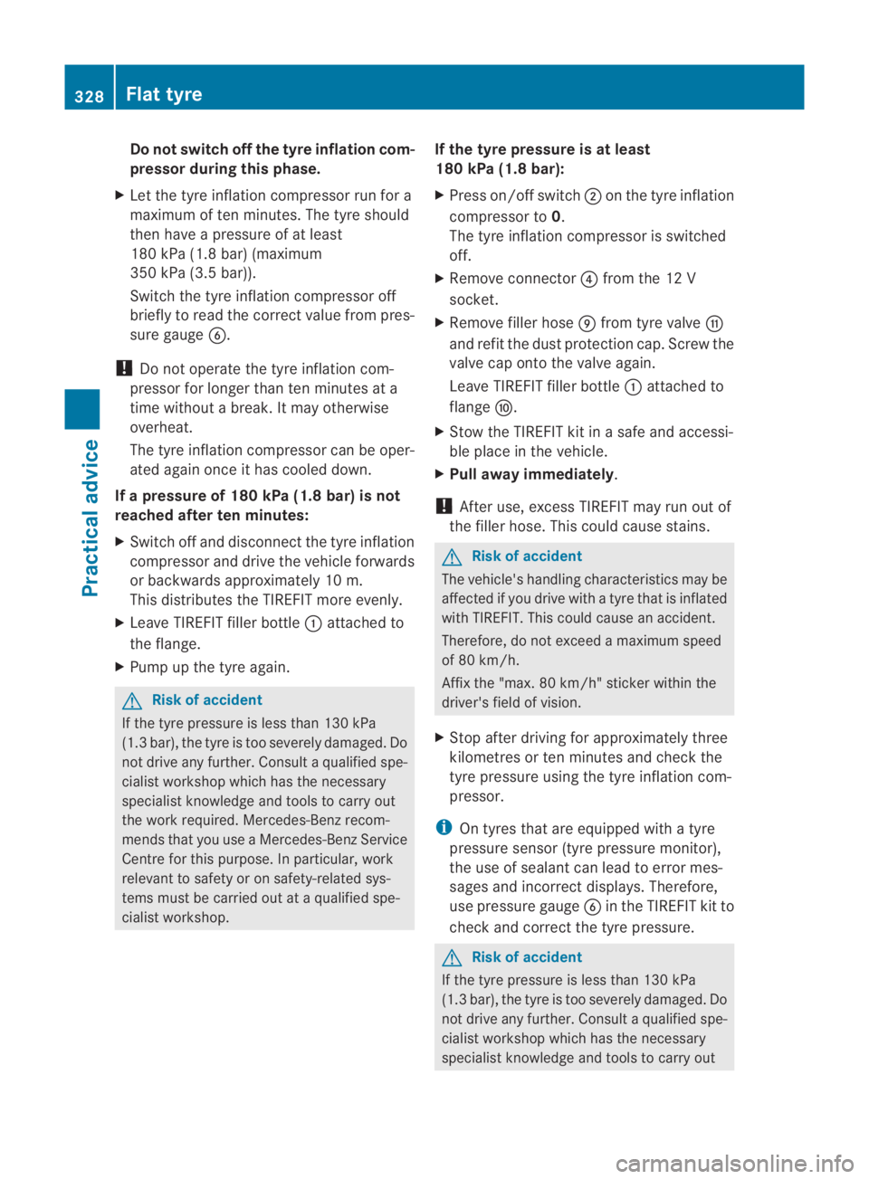
Screw the end of filler hose 000Conto tyre
valve 000E.
X Make sure that on/offs witch0002on the tyre
inflatio ncompressor is set to 0.
X Insert connector 0014into the 12 V cigarette
lighter socket*(Y page 260).
X Select key position 2with the Start/Stop
button (Y page 202).
i The battery discharges during tyre infla-
tion compressor usage. For this reason,
you should start the engine unless you are
inflating the tyre in an enclosed space. X
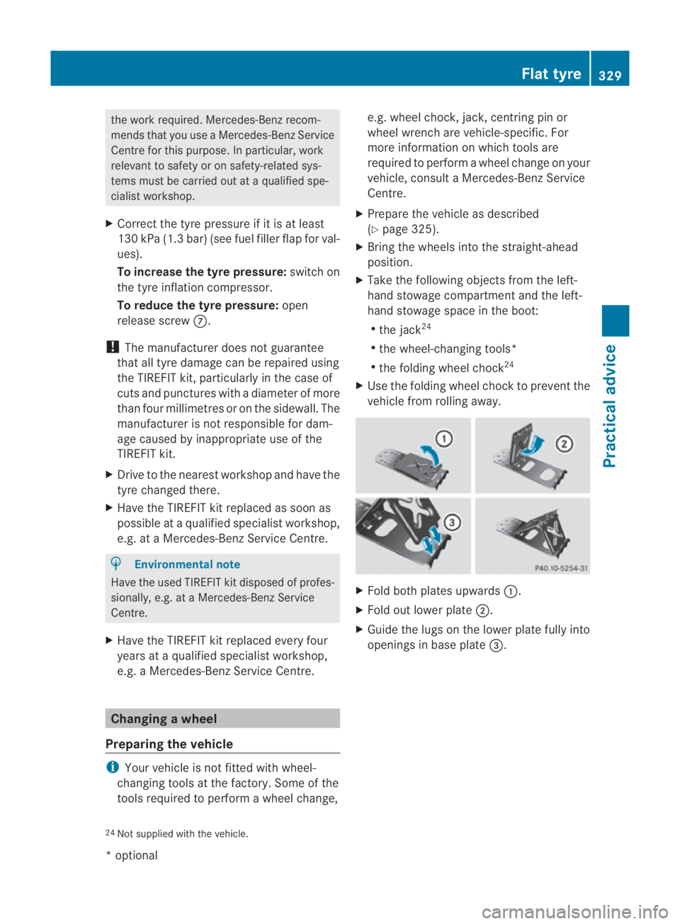
Press on/offs witch0002on the tyre inflation
compressor to I.
The tyre inflatio ncompressor is switched
on. The tyre is inflated.
i First, TIREFIT is pumped into the tyre. The
pressure can briefly rise to approximately
500 kPa (5 bar). Flat tyre
327Practical advice
*optional
BA 197 ECE RE 2010/6a; 1; 2, en-GB
sabbaeu
Version: 3.0.3.6 2010-05-07T14:19:43+02:00 - Seite 327 Z
Page 331 of 361
Do not switch off the tyre inflation com-
pressor during this phase.
X Let the tyre inflation compressor run for a
maximum of te nminutes. The tyre should
the nhave a pressure of at least
180 kPa (1.8 bar) (maximum
350 kPa (3.5 bar)).
Switch the tyre inflation compressor off
briefly to read the correct value from pres-
sure gauge 0013.
! Do not operate the tyre inflation com-
pressor for longer than ten minutes at a
time without a break .Itmay otherwise
overheat.
The tyre inflation compressor can be oper-
ated again once it has cooled down.
If a pressure of 180 kPa (1.8 bar) is not
reached after ten minutes:
X Switch off and disconnect the tyre inflation
compressor and drive the vehicle forwards
or backwards approximately 10 m.
This distributes the TIREFIT more evenly.
X Leave TIREFIT fille rbottle 0001attached to
the flange.
X Pump up the tyre again. G
Risk of accident
If the tyre pressure is less than 130 kPa
(1.3 bar), the tyre is too severely damaged. Do
not drive any further. Consult a qualified spe-
cialist workshop which has the necessary
specialist knowledge and tools to carry out
the work required. Mercedes-Benz recom-
mends that you use a Mercedes-Benz Service
Centre for this purpose. In particular, work
relevant to safety or on safety-related sys-
tems must be carried out at a qualified spe-
cialist workshop. If the tyre pressure is at least
180 kPa (1.8 bar):
X
Press on/offs witch0002on the tyre inflation
compressor to 0.
The tyre inflatio ncompressor is switched
off.
X Remove connector 0014from the 12 V
socket.
X Remove filler hose 000Cfrom tyre valve 000E
and refit the dust protection cap. Screw the
valve cap onto the valve again.
Leave TIREFIT filler bottle 0001attached to
flange 000D.
X Stow the TIREFIT kit in a safe and accessi-
ble place in the vehicle.
X Pull away immediately.
! After use, excess TIREFIT may run out of
the filler hose. This could cause stains. G
Risk of accident
The vehicle's handling characteristics may be
affected if you drive with a tyre that is inflated
with TIREFIT. This could cause an accident.
Therefore, do not exceed amaximum speed
of 80 km/h.
Affix th e"max. 80 km/h" sticker within the
driver's field of vision.
X Stop after driving for approximately three
kilometres or ten minutes and check the
tyre pressure using the tyre inflation com-
pressor.
i On tyres that are equipped with a tyre
pressure sensor (tyre pressure monitor),
the use of sealant can leadt o error mes-
sages and incorrect displays. Therefore,
use pressure gauge 0013in the TIREFIT kit to
check and correct the tyre pressure. G
Risk of accident
If the tyre pressure is less than 130 kPa
(1.3 bar), the tyre is too severely damaged. Do
not drive any further. Consult a qualified spe-
cialist workshop which has the necessary
specialist knowledge and tools to carry out 328
Flat tyrePractical advice
BA 197 ECE RE 2010/6a; 1; 2, en-GB
sabbaeu
Version: 3.0.3.6 2010-05-07T14:19:43+02:00 - Seite 328
Page 332 of 361
the work required. Mercedes-Benz recom-
mends tha
tyou use a Mercedes-Benz Service
Centre for this purpose. In particular, work
relevant to safety or on safety-related sys-
tems must be carried out at a qualified spe-
cialist workshop.
X Correct the tyre pressure if it is at least
130 kPa (1.3 bar) (see fuel filler flap for val-
ues).
To increase the tyre pressure: switch on
the tyre inflation compressor.
To reduce the tyre pressure: open
release screw 000A.
! The manufacturer does not guarantee
that all tyre damage can be repaired using
the TIREFIT kit, particularly in the case of
cuts and punctures with a diameter of more
than four millimetres or on the sidewall. The
manufacturer is not responsible for dam-
age caused by inappropriate use of the
TIREFIT kit.
X Drive to the nearest workshop and have the
tyre changed there.
X Have the TIREFIT kit replaced as soon as
possible at a qualified specialist workshop,
e.g. at a Mercedes-Benz Service Centre. H
Environmental note
Have the used TIREFIT kit disposed of profes-
sionally, e.g. at a Mercedes-Benz Service
Centre.
X Have the TIREFIT kit replaced every four
years at a qualified specialist workshop,
e.g. a Mercedes-Benz Service Centre. Changing
awheel
Preparing the vehicle i
You rvehicle is not fitted with wheel-
changing tools at the factory. Some of the
tools required to perform awheel change, e.g. wheel chock, jack, centring pin or
wheel wrench are vehicle-specific. For
more information on which tools are
required to perform a wheel change on your
vehicle, consult a Mercedes-Ben
zService
Centre.
X Prepare the vehicle as described
(Y page 325).
X Bring the wheels into the straight-ahead
position.
X Take the following objects from the left-
hand stowage compartment and the left-
hand stowage space in the boot:
R
the jack 24
R the wheel-changing tools*
R the folding wheel chock 24
X Use the folding wheel choc kto prevent the
vehicle from rolling away. X
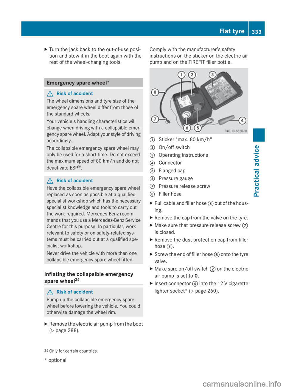
Fold both plates upwards 0001.
X Fold out lower plate 0002.
X Guide the lugs on the lower plate fully into
openings in base plate 0015.
24 Not supplied with the vehicle. Flat tyre
329Practical advice
*optional
BA 197 ECE RE 2010/6a; 1; 2, en-GB
sabbaeu
Version: 3.0.3.6 2010-05-07T14:19:43+02:00 - Seite 329 Z
Page 336 of 361
X
Turn the jack back to the out-of-use posi-
tion and stow it in the boot again with the
rest of the wheel-changing tools. Emergency spare wheel*
G
Risk of accident
The wheel dimensions and tyre size of the
emergency spare wheel differ from those of
the standard wheels.
Your vehicle's handling characteristics will
change when driving with a collapsible emer-
gency spare wheel. Adapt your style of driving
accordingly.
The collapsible emergency spare wheel may
only be used for a short time. Do not exceed
the maximum speed of 80 km/h and do not
deactivate ESP ®
. G
Risk of accident
Have the collapsible emergenc yspare wheel
replaced as soon as possible at a qualified
specialist workshop which has the necessary
specialist knowledge and tools to carry out
the work required. Mercedes-Benz recom-
mends that you use a Mercedes-Benz Service
Centre for this purpose. In particular, work
relevant to safety or on safety-related sys-
tems must be carried out at a qualified spe-
cialist workshop.
Never drive the vehicle with more than one
collapsible emergency spare wheel fitted.
Inflating the collapsible emergency
spare wheel 25 G
Risk of accident
Pump up the collapsible emergency spare
wheel before lowering the vehicle. You could
otherwise damage the wheel rim.
X Remove the electric air pump from the boot
(Y page 288). Comply with the manufacturer’s safety
instructions on the sticker on the electric air
pump and on the TIREFIT filler bottle.
0001
Sticker "max. 80 km/h“
0002 On/off switch
0015 Operating instructions
0014 Connector
0012 Flanged cap
0013 Pressure gauge
000A Pressure release screw
000B Filler hose
X Pull cable and filler hose 000Bout of the hous-
ing.
X Remove the cap from the valve on the tyre.
X Make sure that pressure release screw 000A
is closed.
X Remove the dust protection cap from filler
hose 000B.
X Screw the end of filler hose 000Bonto the tyre
valve.
X Make sure on/off switch 0002on the electric
air pump is set to 0.
X Insert connector 0014intothe 12 V cigarette
lighter socket*( Ypage 260).
25 Only for certain countries. Flat tyre
333Practical advice
*optional
BA 197 ECE RE 2010/6a; 1; 2, en-GB
sabbaeu Version: 3.0.3.6 2010-05-07T14:19:43+02:00 - Seite 333 Z