2010 MERCEDES-BENZ R350 transmission
[x] Cancel search: transmissionPage 160 of 364
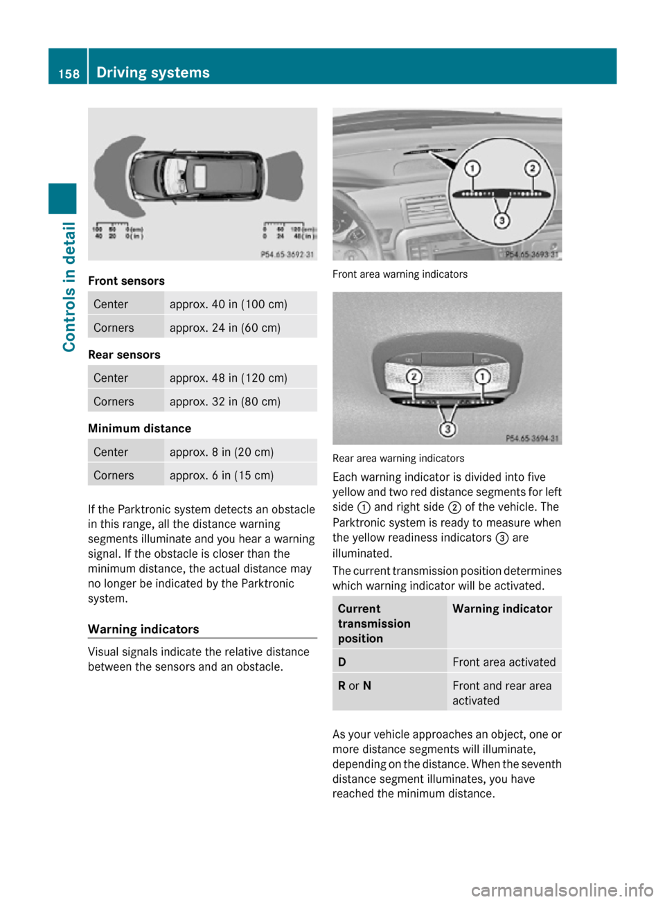
Front sensors
Center approx. 40 in (100 cm)
Corners approx. 24 in (60 cm)
Rear sensors
Center approx. 48 in (120 cm)
Corners approx. 32 in (80 cm)
Minimum distance
Center approx. 8 in (20 cm)
Corners approx. 6 in (15 cm)
If the Parktronic system detects an obstacle
in this range, all the distance warning
segments illuminate and you hear a warning
signal. If the obstacle is closer than the
minimum distance, the actual distance may
no longer be indicated by the Parktronic
system.
Warning indicators
Visual signals indicate the relative distance
between the sensors and an obstacle. Front area warning indicators
Rear area warning indicators
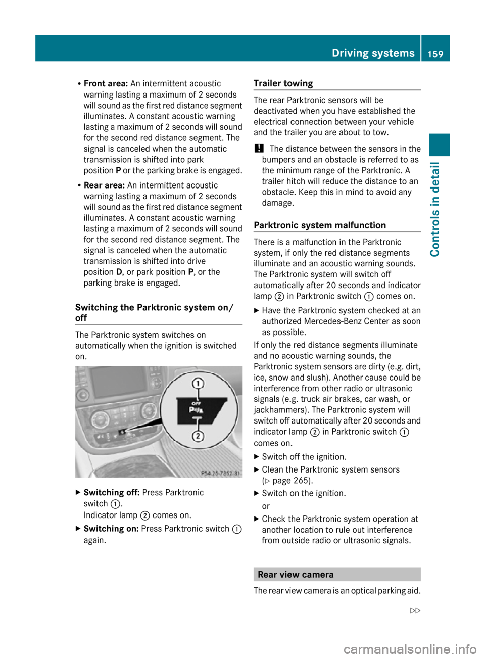
Each warning indicator is divided into five
yellow and two red distance segments for left
side
: and right side ; of the vehicle. The
Parktronic system is ready to measure when
the yellow readiness indicators = are
illuminated.
The current transmission position determines
which warning indicator will be activated. Current
transmission
position Warning indicator
D
Front area activated
R or N Front and rear area
activated
As your vehicle approaches an object, one or
more distance segments will illuminate,
depending on the distance. When the seventh
distance segment illuminates, you have
reached the minimum distance.158
Driving systemsControls in detail
251_AKB; 4; 52, en-US
d2ureepe,
Version: 2.11.8.1 2009-03-23T09:22:52+01:00 - Seite 158
Page 161 of 364
R
Front area: An intermittent acoustic
warning lasting a maximum of 2 seconds
will sound as the first red distance segment
illuminates. A constant acoustic warning
lasting a maximum of 2 seconds will sound
for the second red distance segment. The
signal is canceled when the automatic
transmission is shifted into park
position P or the parking brake is engaged.
R Rear area: An intermittent acoustic
warning lasting a maximum of 2 seconds
will sound as the first red distance segment
illuminates. A constant acoustic warning
lasting a maximum of 2 seconds will sound
for the second red distance segment. The
signal is canceled when the automatic
transmission is shifted into drive
position D, or park position P, or the
parking brake is engaged.
Switching the Parktronic system on/
off The Parktronic system switches on
automatically when the ignition is switched
on.
X
Switching off: Press Parktronic
switch :.
Indicator lamp ; comes on.
X Switching on: Press Parktronic switch :
again. Trailer towing The rear Parktronic sensors will be
deactivated when you have established the
electrical connection between your vehicle
and the trailer you are about to tow.
!
The distance between the sensors in the
bumpers and an obstacle is referred to as
the minimum range of the Parktronic. A
trailer hitch will reduce the distance to an
obstacle. Keep this in mind to avoid any
damage.
Parktronic system malfunction There is a malfunction in the Parktronic
system, if only the red distance segments
illuminate and an acoustic warning sounds.
The Parktronic system will switch off
automatically after 20 seconds and indicator
lamp
; in Parktronic switch : comes on.
X Have the Parktronic system checked at an
authorized Mercedes-Benz Center as soon
as possible.
If only the red distance segments illuminate
and no acoustic warning sounds, the
Parktronic system sensors are dirty (e.g. dirt,
ice, snow and slush). Another cause could be
interference from other radio or ultrasonic
signals (e.g. truck air brakes, car wash, or
jackhammers). The Parktronic system will
switch off automatically after 20 seconds and
indicator lamp ; in Parktronic switch :
comes on.
X Switch off the ignition.
X Clean the Parktronic system sensors
(Y page 265).
X Switch on the ignition.
or
X Check the Parktronic system operation at
another location to rule out interference
from outside radio or ultrasonic signals. Rear view camera
The rear view camera is an optical parking aid. Driving systems
159Controls in detail
251_AKB; 4; 52, en-US
d2ureepe, Version: 2.11.8.1 2009-03-23T09:22:52+01:00 - Seite 159 Z
Page 163 of 364
Switching on/off
X
Switching on: Switch on the ignition.
X Switch on the COMAND system.
X Shift the automatic transmission to reverse
gear R.
The COMAND system display will show the
area behind the vehicle with guidelines. G
Warning!
Please note that objects which do not touch
the ground may appear to be further away
than they actually are, for example:
R the bumper of a vehicle parked behind you
R a trailer hitch
R the back of a truck
In such cases, you should not use the
guidelines to judge the distance. You may
misjudge the distance which increases the
risk of impacting the objects.
Even when the object you approach is directly
on the ground do not approach the object any
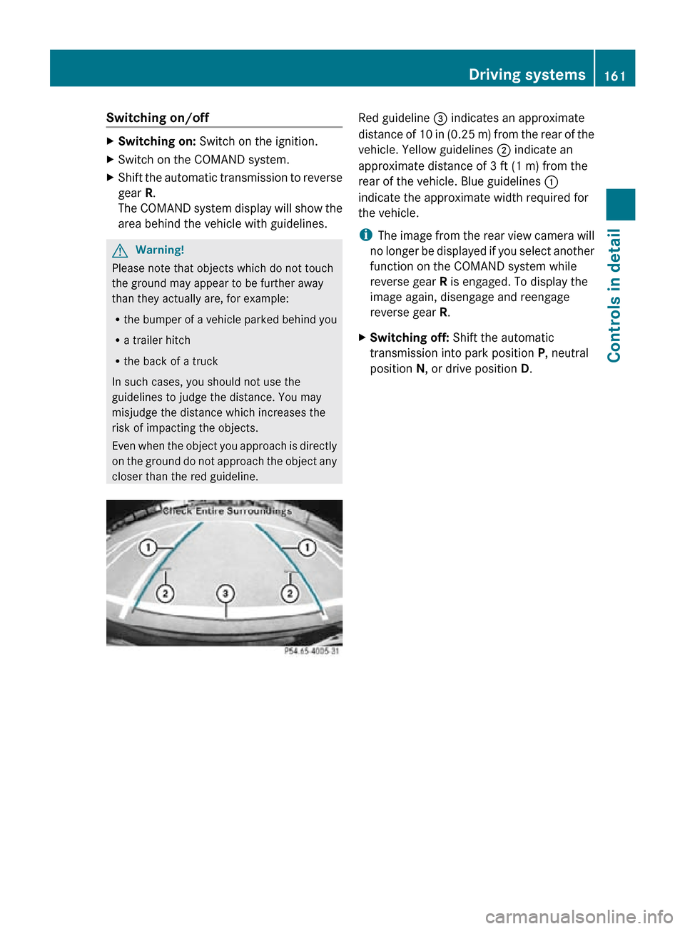
closer than the red guideline. Red guideline
= indicates an approximate
distance of 10 in (0.25 m) from the rear of the
vehicle. Yellow guidelines ; indicate an
approximate distance of 3 ft (1 m) from the
rear of the vehicle. Blue guidelines :
indicate the approximate width required for
the vehicle.
i The image from the rear view camera will
no longer be displayed if you select another
function on the COMAND system while
reverse gear R is engaged. To display the
image again, disengage and reengage
reverse gear R.
X Switching off: Shift the automatic
transmission into park position P, neutral
position N, or drive position D. Driving systems
161Controls in detail
251_AKB; 4; 52, en-US
d2ureepe, Version: 2.11.8.1 2009-03-23T09:22:52+01:00 - Seite 161 Z
Page 216 of 364
X
Step 4: Using both hands, simultaneously
press hand-held remote control button B
and the desired signal transmitter button
(;, = or ?). Do not release the buttons
until step 5 is completed.
Indicator
lamp : will flash, first slowly and
then rapidly.
i Indicator lamp : flashes immediately
the first time the signal transmitter button
is programmed. If this button has already
been programmed, the indicator lamp will
start flashing after 20 seconds.
X Step 5: After indicator lamp : changes
from a slow to a rapidly flashing light,
release the hand-held remote control
button and the signal transmitter button.
X Step 6: Press and hold the just-trained
signal
transmitter button (;, = or ?) and
observe indicator lamp :.
If indicator lamp : stays on constantly,
programming is complete and your device
should activate when the respective signal
transmitter button ( ;, = or ?) is pressed
and released.
i If indicator lamp : flashes rapidly for
approximately
2 seconds and then turns to
a constant light, continue with
programming steps 8 through 12 as your
garage door opener may be equipped with
the “rolling code” feature.
X Step 7: To program the remaining two
signal
transmitter buttons, repeat the steps
above starting with step 3.
Rolling code programming
To
train a garage door opener (or other rolling
code devices) with the rolling code feature,
follow these instructions after completing the
“Programming” portion (steps 1 through 6) of
this text. For your convenience and to
complete the procedure faster, you might
want to have someone assist you. X
Step 8:
Locate the “training” button on the
garage door opener motor head unit.
i Exact
location and color of the button may
vary by garage door opener brand.
Depending on manufacturer, the “training”
button may also be referred to as “learn” or
“smart” button. If there is difficulty locating
the transmitting button, refer to the garage
door opener Operator’s Manual.
X Step 9: Press the “training” button on the
garage door opener motor head unit.
The “training light” is activated.
You have 30 seconds to initiate the
following two steps.
X Step 10: Return to the vehicle and firmly
press, hold for 2 seconds and release the
programmed
signal transmitter button (;,
= or ?).
X Step 11: Press, hold for 2 seconds and
release same signal transmitter button a
second time to complete the training
process.
i Some garage door openers (or other
rolling
code equipped devices) may require
you to press, hold for 2 seconds and
release the same signal transmitter button
a third time to complete the training
process.
X Step 12: Confirm the garage door
operation by pressing the programmed
signal transmitter button ( ;, = or ?).
X Step 13: To program the remaining two
signal
transmitter buttons, repeat the steps
above starting with step 3.
Gate operator/Canadian programming
Canadian radio-frequency laws require
transmitter signals to “time-out” (or quit)
after several seconds of transmission which
may not be long enough for the integrated
signal
transmitter to pick up the signal during
programming. Similar to this Canadian law,
some U.S. gate operators are designed to
“time-out” in the same manner. 214
Useful features
Controls in detail
251_AKB; 4; 52, en-US
d2ureepe,
Version: 2.11.8.1 2009-03-23T09:22:52+01:00 - Seite 214
Page 219 of 364
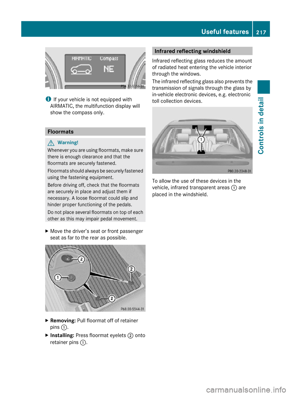
i
If your vehicle is not equipped with
AIRMATIC, the multifunction display will
show the compass only. Floormats
G
Warning!
Whenever you are using floormats, make sure
there is enough clearance and that the
floormats are securely fastened.
Floormats should always be securely fastened
using the fastening equipment.
Before driving off, check that the floormats
are securely in place and adjust them if
necessary. A loose floormat could slip and
hinder proper functioning of the pedals.
Do not place several floormats on top of each
other as this may impair pedal movement.
X Move the driver’s seat or front passenger
seat as far to the rear as possible. X
Removing: Pull floormat off of retainer
pins :.
X Installing: Press floormat eyelets ; onto
retainer pins :. Infrared reflecting windshield
Infrared reflecting glass reduces the amount
of radiated heat entering the vehicle interior
through the windows.
The infrared reflecting glass also prevents the
transmission of signals through the glass by
in-vehicle electronic devices, e.g. electronic
toll collection devices. To allow the use of these devices in the
vehicle, infrared transparent areas
: are
placed in the windshield. Useful features
217Controls in detail
251_AKB; 4; 52, en-US
d2ureepe, Version: 2.11.8.1 2009-03-23T09:22:52+01:00 - Seite 217 Z
Page 227 of 364
For more information on engine oil, see
“Fuels, coolants, lubricants etc.”
(Y page 350).
For information on messages in the
multifunction display concerning engine oil,
see the “Practical hints” section
(Y page 293).
Adding engine oil
!
Only use approved engine oils and oil
filters required for vehicles with
Maintenance System. For a listing of
approved engine oils and oil filters, contact
an authorized Mercedes-Benz Center or
visit www.mbusa.com (USA only).
The following will result in engine or
emission control system damage not
covered by the Mercedes-Benz Limited
Warranty:
R Using engine oils and oil filters of
specification other than those expressly
required for the Maintenance System.
R Changing of oil and oil filter at change
intervals longer than those called for by
the Maintenance System.
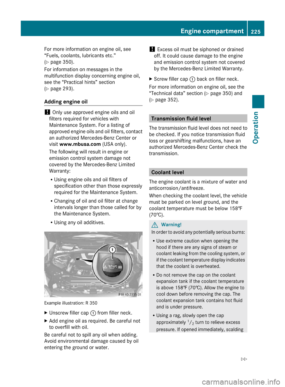
R Using any oil additives. Example illustration: R 350
X
Unscrew filler cap : from filler neck.
X Add engine oil as required. Be careful not
to overfill with oil.
Be careful not to spill any oil when adding.
Avoid environmental damage caused by oil
entering the ground or water. !
Excess oil must be siphoned or drained
off. It could cause damage to the engine
and emission control system not covered
by the Mercedes-Benz Limited Warranty.
X Screw filler cap : back on filler neck.
For more information on engine oil, see the
“Technical data” section ( Y page 350) and
(Y page 352). Transmission fluid level
The transmission fluid level does not need to
be checked. If you notice transmission fluid
loss or gearshifting malfunctions, have an
authorized Mercedes-Benz Center check the
transmission. Coolant level
The engine coolant is a mixture of water and
anticorrosion/antifreeze.
When checking the coolant level, the vehicle
must be parked on level ground, and the
coolant temperature must be below 158‡
(70†). G
Warning!
In order to avoid any potentially serious burns:
R Use extreme caution when opening the
hood if there are any signs of steam or
coolant leaking from the cooling system, or
if the coolant temperature display indicates
that the coolant is overheated.
R Do not remove the cap on the coolant
expansion tank if the coolant temperature
is above 158‡ (70†). Allow the engine to
cool down before removing the cap. The
coolant expansion tank contains hot fluid
and is under pressure.
R Using a rag, slowly open the cap
approximately 1
/ 2 turn to relieve excess
pressure. If opened immediately, scalding Engine compartment
225Operation
251_AKB; 4; 52, en-US
d2ureepe, Version: 2.11.8.1 2009-03-23T09:22:52+01:00 - Seite 225 Z
Page 236 of 364
malfunction using the TPMS telltale
flashing and illumination sequence.
The telltale extinguishes after a few
minutes driving if the malfunction has been
corrected.
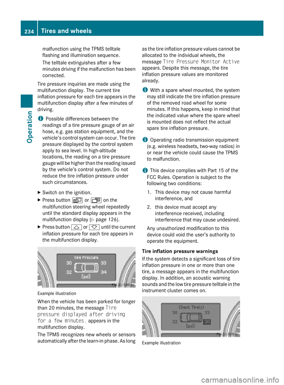
Tire pressure inquiries are made using the
multifunction display. The current tire
inflation pressure for each tire appears in the
multifunction display after a few minutes of
driving.
i Possible differences between the
readings of a tire pressure gauge of an air
hose, e.g. gas station equipment, and the
vehicle’s control system can occur. The tire
pressure displayed by the control system
apply to sea level. In high-altitude
locations, the reading on a tire pressure
gauge will be higher than the reading issued
by the vehicle’s control system. Do not
reduce the tire inflation pressure under
such circumstances.
X Switch on the ignition.
X Press button V or U on the
multifunction steering wheel repeatedly
until the standard display appears in the
multifunction display ( Y page 126).
X Press button & or * until the current
inflation pressure for each tire appears in
the multifunction display. Example illustration
When the vehicle has been parked for longer
than 20 minutes, the message Tire
pressure displayed after driving
for a few minutes. appears in the
multifunction display.
The TPMS recognizes new wheels or sensors
automatically after the learn-in phase. As long as the tire inflation pressure values cannot be
allocated to the individual wheels, the
message
Tire Pressure Monitor Active
appears. Despite this message, the tire
inflation pressure values are monitored
already.
i With a spare wheel mounted, the system
may still indicate the tire inflation pressure
of the removed road wheel for some
minutes. If this happens, keep in mind that
the indicated value where the spare wheel
is mounted does not reflect the actual
spare tire inflation pressure.
i Operating radio transmission equipment
(e.g. wireless headsets, two-way radios) in
or near the vehicle could cause the TPMS
to malfunction.
i This device complies with Part 15 of the
FCC Rules. Operation is subject to the
following two conditions:
1. This device may not cause harmful interference, and
2. this device must accept any interference received, including
interference that may cause undesired.
Any unauthorized modification to this
device could void the user’s authority to
operate the equipment.
Tire inflation pressure warnings
If the system detects a significant loss of tire
inflation pressure in one or more than one
tire, a message appears in the multifunction
display. In addition, an acoustic warning
sounds and the low tire pressure telltale in the
instrument cluster comes on. Example illustration234
Tires and wheelsOperation
251_AKB; 4; 52, en-US
d2ureepe,
Version: 2.11.8.1 2009-03-23T09:22:52+01:00 - Seite 234
Page 250 of 364
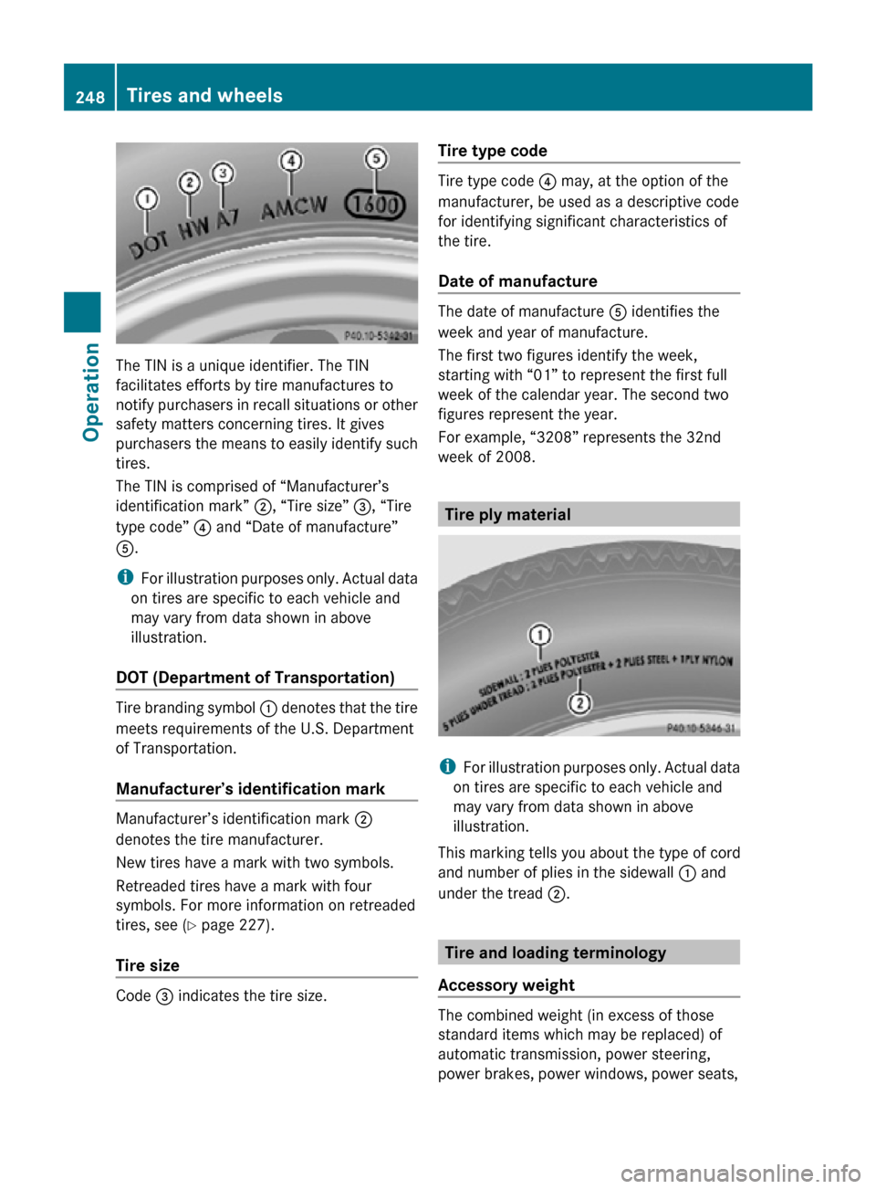
The TIN is a unique identifier. The TIN
facilitates efforts by tire manufactures to
notify purchasers in recall situations or other
safety matters concerning tires. It gives
purchasers the means to easily identify such
tires.
The TIN is comprised of “Manufacturer’s
identification mark” ;, “Tire size”
=, “Tire
type code” ? and “Date of manufacture”
A.
i For illustration purposes only. Actual data
on tires are specific to each vehicle and
may vary from data shown in above
illustration.
DOT (Department of Transportation) Tire branding symbol
: denotes that the tire
meets requirements of the U.S. Department
of Transportation.
Manufacturer’s identification mark Manufacturer’s identification mark ;
denotes the tire manufacturer.
New tires have a mark with two symbols.
Retreaded tires have a mark with four
symbols. For more information on retreaded
tires, see (
Y page 227).
Tire size Code
= indicates the tire size. Tire type code Tire type code
? may, at the option of the
manufacturer, be used as a descriptive code
for identifying significant characteristics of
the tire.
Date of manufacture The date of manufacture
A identifies the
week and year of manufacture.
The first two figures identify the week,
starting with “01” to represent the first full
week of the calendar year. The second two
figures represent the year.
For example, “3208” represents the 32nd
week of 2008. Tire ply material
i
For illustration purposes only. Actual data
on tires are specific to each vehicle and
may vary from data shown in above
illustration.
This marking tells you about the type of cord
and number of plies in the sidewall : and
under the tread ;. Tire and loading terminology
Accessory weight The combined weight (in excess of those
standard items which may be replaced) of
automatic transmission, power steering,
power brakes, power windows, power seats,248
Tires and wheelsOperation
251_AKB; 4; 52, en-US
d2ureepe,
Version: 2.11.8.1 2009-03-23T09:22:52+01:00 - Seite 248