2010 MERCEDES-BENZ ML450 HYBRID light
[x] Cancel search: lightPage 2 of 44

Symbols
Trademarks
®
:
R ESP ®
is a registered trademark of Daimler.
The following symbols are found in this
Supplemental Operating Instructions: G
Warning!
Warning notices draw your attention to
hazards
that may endanger your health or life,
or the health or life of others.
! Highlights hazards that may result in
damage to your vehicle.
i Helpful hints or further information you
may find useful.
X This symbol points to instructions
for you to follow.
X A number of these symbols
appearing in succession indicates
a multiple-step procedure.
Y page This symbol tells you where to look
for further information on a topic.
YY This continuation symbol marks a
warning or procedure which is
continued on the next page.
Display Text in displays, such as the control
system, are printed in the type
shown here.
164_ZA; 2; 2, en-US
d2ureepe,
Version: 2.11.8.1 2009-05-12T15:08:04+02:00 - Seite 2
Page 16 of 44

Selecting submenu in the
multifunction display
Use the buttons on the multifunction steering
wheel.
X Press button V or U repeatedly until
the standard display appears.
X Press button & or * to select the
HYBRID menu. Selecting submenu in the COMAND
display
X Select System Q Hybrid Q Energy
Flow. COMAND display examples
Example illustration: Operating mode display
1
Combustion engine
2 Hybrid transmission
3 High-voltage battery
4 Charging condition of high-voltage
battery in percent
5 Flow of energy
The HYBRID components that are currently
active are highlighted in the COMAND
display. Multifunction display Power gauge COMAND display
Recuperation – the hybrid transmission functions as a generator, for example when
coasting or braking. The kinetic energy of the vehicle is converted into electric power and
stored in the high-voltage battery.
The multifunction display indicates charging of the high-voltage battery by an arrow pointing
upwards. The pointer of the power gauge moves into the charge section. The COMAND
display indicates the flow of energy by green arrows.14
Controls in detail 164_ZA; 2; 2, en-US
d2ureepe,
Version: 2.11.8.1 2009-05-12T15:08:04+02:00 - Seite 14
Page 34 of 44

X
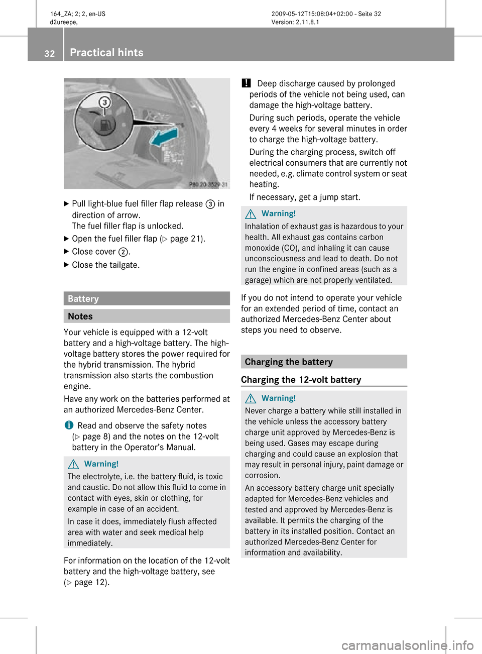
Pull light-blue fuel filler flap release = in
direction of arrow.
The fuel filler flap is unlocked.
X Open the fuel filler flap ( Y page 21).
X Close cover ;.
X Close the tailgate. Battery
Notes
Your vehicle is equipped with a 12-volt
battery and a high-voltage battery. The high-
voltage battery stores the power required for
the hybrid transmission. The hybrid
transmission also starts the combustion
engine.
Have any work on the batteries performed at
an authorized Mercedes-Benz Center.
i Read and observe the safety notes
(Y page 8) and the notes on the 12-volt
battery in the Operator’s Manual. G
Warning!
The electrolyte, i.e. the battery fluid, is toxic
and caustic. Do not allow this fluid to come in
contact with eyes, skin or clothing, for
example in case of an accident.
In case it does, immediately flush affected
area with water and seek medical help
immediately.
For information on the location of the 12-volt
battery and the high-voltage battery, see
(Y page 12). !
Deep discharge caused by prolonged
periods of the vehicle not being used, can
damage the high-voltage battery.
During such periods, operate the vehicle
every 4 weeks for several minutes in order
to charge the high-voltage battery.
During the charging process, switch off
electrical consumers that are currently not
needed, e.g. climate control system or seat
heating.
If necessary, get a jump start. G
Warning!
Inhalation of exhaust gas is hazardous to your
health. All exhaust gas contains carbon
monoxide (CO), and inhaling it can cause
unconsciousness and lead to death. Do not
run the engine in confined areas (such as a
garage) which are not properly ventilated.
If you do not intend to operate your vehicle
for an extended period of time, contact an
authorized Mercedes-Benz Center about
steps you need to observe. Charging the battery
Charging the 12-volt battery G
Warning!
Never charge a battery while still installed in
the vehicle unless the accessory battery
charge unit approved by Mercedes-Benz is
being used. Gases may escape during
charging and could cause an explosion that
may result in personal injury, paint damage or
corrosion.
An accessory battery charge unit specially
adapted for Mercedes-Benz vehicles and
tested and approved by Mercedes-Benz is
available. It permits the charging of the
battery in its installed position. Contact an
authorized Mercedes-Benz Center for
information and availability. 32
Practical hints 164_ZA; 2; 2, en-US
d2ureepe,
Version: 2.11.8.1 2009-05-12T15:08:04+02:00 - Seite 32
Page 36 of 44

Make sure the cable clamps do not touch
any other metal part while the other end is
still attached to a battery.
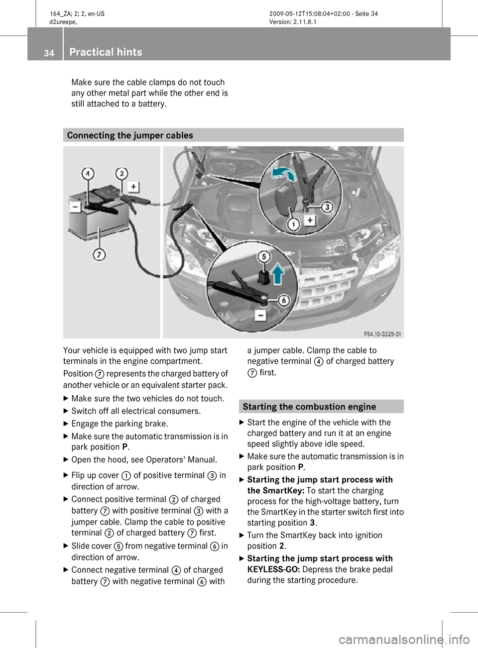
Connecting the jumper cables
Your vehicle is equipped with two jump start
terminals in the engine compartment.
Position
C represents the charged battery of
another vehicle or an equivalent starter pack.
X Make sure the two vehicles do not touch.
X Switch off all electrical consumers.
X Engage the parking brake.
X Make sure the automatic transmission is in
park position P.
X Open the hood, see Operators' Manual.
X Flip up cover : of positive terminal = in
direction of arrow.
X Connect positive terminal ; of charged
battery C with positive terminal = with a
jumper cable. Clamp the cable to positive
terminal ; of charged battery C first.
X Slide cover A from negative terminal B in
direction of arrow.
X Connect negative terminal ? of charged
battery C with negative terminal B with a jumper cable. Clamp the cable to
negative terminal ? of charged battery
C first. Starting the combustion engine
X Start the engine of the vehicle with the
charged battery and run it at an engine
speed slightly above idle speed.
X Make sure the automatic transmission is in
park position P.
X Starting the jump start process with
the SmartKey: To start the charging
process for the high-voltage battery, turn
the SmartKey in the starter switch first into
starting position 3.
X Turn the SmartKey back into ignition
position 2.
X Starting the jump start process with
KEYLESS-GO: Depress the brake pedal
during the starting procedure. 34
Practical hints 164_ZA; 2; 2, en-US
d2ureepe,
Version: 2.11.8.1 2009-05-12T15:08:04+02:00 - Seite 34
Page 39 of 44

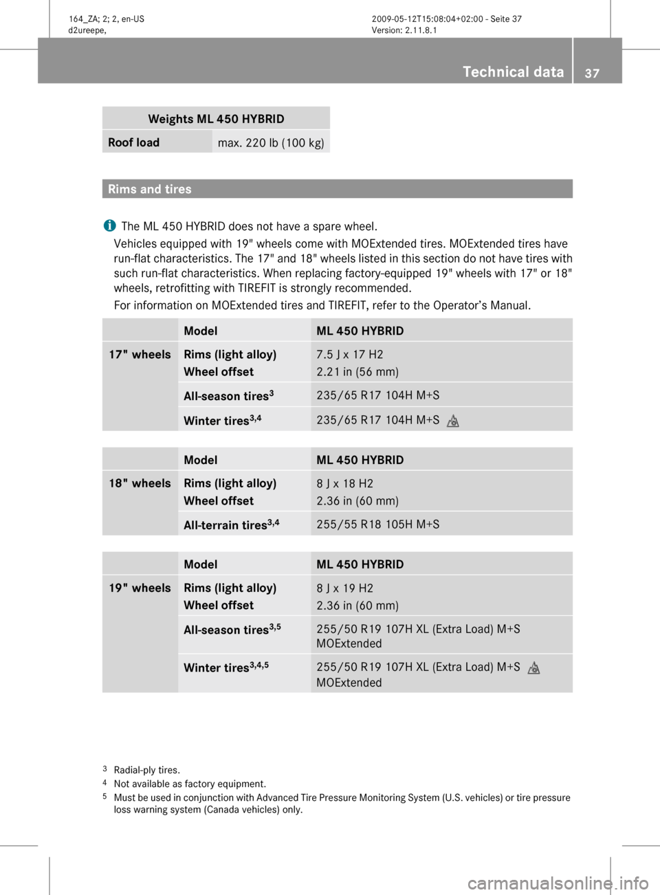
Weights ΜL 450 HYBRID
Roof load
max. 220 lb (100 kg)
Rims and tires
i The ML 450 HYBRID does not have a spare wheel.
Vehicles equipped with 19" wheels come with MOExtended tires. MOExtended tires have
run-flat
characteristics. The 17" and 18" wheels listed in this section do not have tires with
such run-flat characteristics. When replacing factory-equipped 19" wheels with 17" or 18"
wheels, retrofitting with TIREFIT is strongly recommended.
For information on MOExtended tires and TIREFIT, refer to the Operator’s Manual. Model ML 450 HYBRID
17" wheels Rims (light alloy)
Wheel offset
7.5 J x 17 H2
2.21 in (56 mm)
All-season tires
3 235/65 R17 104H M+S
Winter tires
3,4 235/65 R17 104H M+S
i Model ML 450 HYBRID
18" wheels Rims (light alloy)
Wheel offset
8 J x 18 H2
2.36 in (60 mm)
All-terrain tires
3,4 255/55 R18 105H M+S
Model ML 450 HYBRID
19" wheels Rims (light alloy)
Wheel offset
8 J x 19 H2
2.36 in (60 mm)
All-season tires
3,5 255/50 R19 107H XL (Extra Load) M+S
MOExtended
Winter tires
3,4,5 255/50 R19 107H XL (Extra Load) M+S
i
MOExtended 3
Radial-ply tires.
4 Not available as factory equipment.
5 Must
be used in conjunction with Advanced Tire Pressure Monitoring System (U.S. vehicles) or tire pressure
loss warning system (Canada vehicles) only. Technical data
37164_ZA; 2; 2, en-US
d2ureepe,
Version: 2.11.8.1 2009-05-12T15:08:04+02:00 - Seite 37 Z