2010 MERCEDES-BENZ ML350 rear cargo
[x] Cancel search: rear cargoPage 229 of 368

punctured or damaged by road debris,
potholes etc.
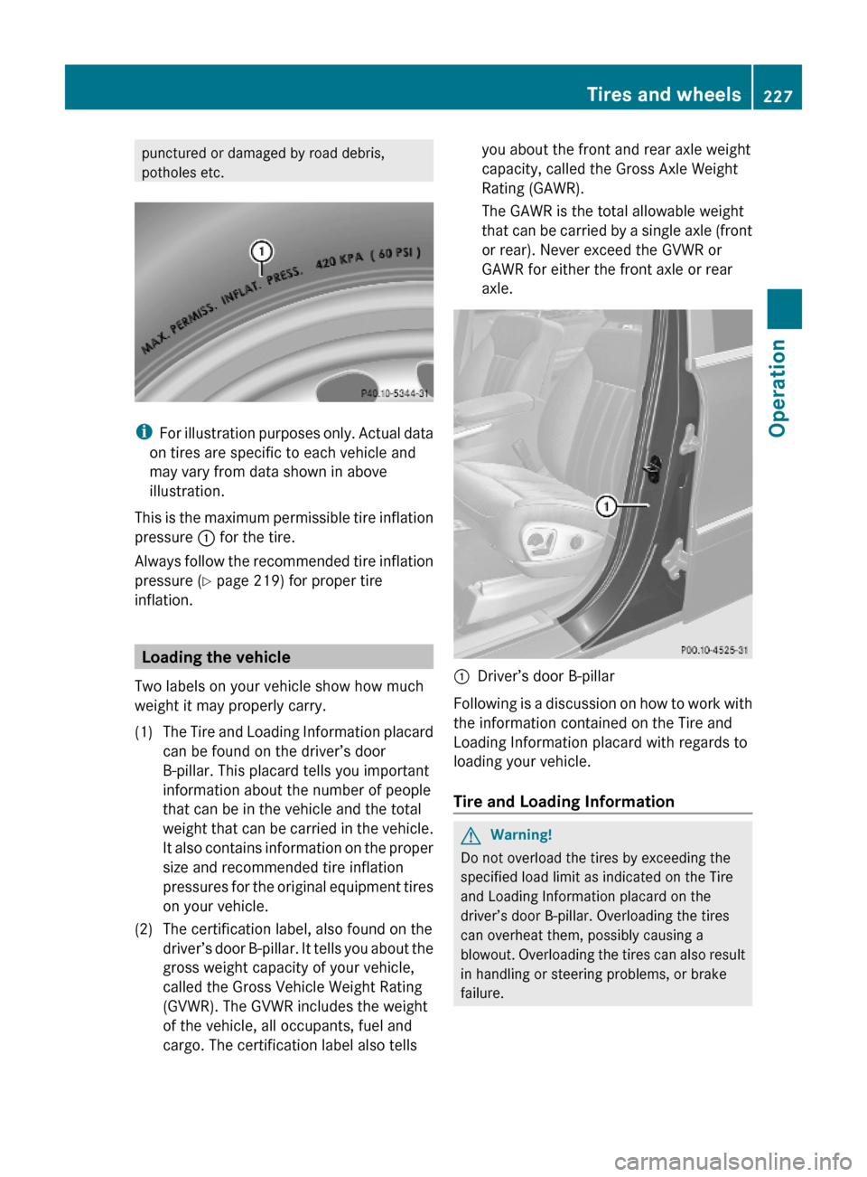
iFor illustration purposes only. Actual data
on tires are specific to each vehicle and
may vary from data shown in above
illustration.
This is the maximum permissible tire inflation
pressure : for the tire.
Always follow the recommended tire inflation
pressure (Y page 219) for proper tire
inflation.
Loading the vehicle
Two labels on your vehicle show how much
weight it may properly carry.
(1)The Tire and Loading Information placard
can be found on the driver’s door
B-pillar. This placard tells you important
information about the number of people
that can be in the vehicle and the total
weight that can be carried in the vehicle.
It also contains information on the proper
size and recommended tire inflation
pressures for the original equipment tires
on your vehicle.
(2)The certification label, also found on the
driver’s door B-pillar. It tells you about the
gross weight capacity of your vehicle,
called the Gross Vehicle Weight Rating
(GVWR). The GVWR includes the weight
of the vehicle, all occupants, fuel and
cargo. The certification label also tells
you about the front and rear axle weight
capacity, called the Gross Axle Weight
Rating (GAWR).
The GAWR is the total allowable weight
that can be carried by a single axle (front
or rear). Never exceed the GVWR or
GAWR for either the front axle or rear
axle.
:Driver’s door B-pillar
Following is a discussion on how to work with
the information contained on the Tire and
Loading Information placard with regards to
loading your vehicle.
Tire and Loading Information
GWarning!
Do not overload the tires by exceeding the
specified load limit as indicated on the Tire
and Loading Information placard on the
driver’s door B-pillar. Overloading the tires
can overheat them, possibly causing a
blowout. Overloading the tires can also result
in handling or steering problems, or brake
failure.
Tires and wheels227Operation164_AKB; 7; 31, en-USd2ureepe,Version: 2.11.8.12009-09-11T12:07:36+02:00 - Seite 227Z
Page 230 of 368

Tire and Loading Information placard
iData shown on Tire and Loading
Information placard example are for
illustration purposes only. Load limit data
are specific to each vehicle and may vary
from data shown in the following
illustration. Refer to Tire and Loading
Information placard on vehicle for actual
data specific to your vehicle.
The Tire and Loading Information placard
showing load limit information : is located
on the driver’s door B-pillar (Y page 227).
XLocate the statement “The combined
weight of occupants and cargo should
never exceed XXX kilograms or XXX lbs.”
on the Tire and Loading Information
placard.
The combined weight of all occupants,
cargo/luggage and trailer tongue load (if
applicable) should never exceed the weight
referenced in that statement.
Seating capacity
iData shown on Tire and Loading
Information placard example are for
illustration purposes only. Seating capacity
data are specific to each vehicle and may
vary from data shown in the following
illustration. Refer to Tire and Loading
Information placard on vehicle for actual
data specific to your vehicle.
The seating capacity gives you important
information on the number of occupants that
can be in the vehicle. Observe front and rear
seating capacity. The Tire and Loading
Information placard showing seating
capacity : is located on the driver’s door
B-pillar (Y page 227).
Steps for determining correct load limit
The following steps have been developed as
required of all manufacturers under Title 49,
Code of U.S. Federal Regulations, Part 575
pursuant to the “National Traffic and Motor
Vehicle Safety Act of 1966”.
XStep 1: Locate the statement “The
combined weight of occupants and cargo
should never exceed XXX kg or XXX lbs.”
on your vehicle’s Tire and Loading
Information placard.
XStep 2: Determine the combined weight of
the driver and passengers that will be riding
in your vehicle.
XStep 3: Subtract the combined weight of
the driver and passengers from
XXX kilograms or XXX lbs.
XStep 4: The resulting figure equals the
available amount of cargo and luggage load
capacity. For example, if the “XXX” amount
equals 1 400 lbs and there will be five
150 lbs passengers in your vehicle, the
amount of available cargo and luggage load
capacity is 650 lbs
(1 400 - 750 (5 x 150) = 650 lbs).
228Tires and wheelsOperation
164_AKB; 7; 31, en-USd2ureepe,Version: 2.11.8.12009-09-11T12:07:36+02:00 - Seite 228
Page 232 of 368

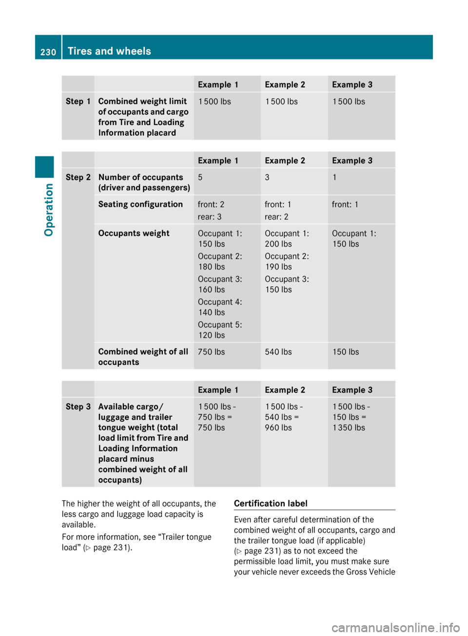
Example 1Example 2Example 3Step 1Combined weight limit
of occupants and cargo
from Tire and Loading
Information placard1 500 lbs1 500 lbs1 500 lbsExample 1Example 2Example 3Step 2Number of occupants
(driver and passengers)531Seating configurationfront: 2
rear: 3front: 1
rear: 2front: 1Occupants weightOccupant 1:
150 lbs
Occupant 2:
180 lbs
Occupant 3:
160 lbs
Occupant 4:
140 lbs
Occupant 5:
120 lbsOccupant 1:
200 lbs
Occupant 2:
190 lbs
Occupant 3:
150 lbsOccupant 1:
150 lbsCombined weight of all
occupants750 lbs540 lbs150 lbsExample 1Example 2Example 3Step 3Available cargo/
luggage and trailer
tongue weight (total
load limit from Tire and
Loading Information
placard minus
combined weight of all
occupants)1 500 lbs -
750 lbs =
750 lbs1 500 lbs -
540 lbs =
960 lbs1 500 lbs -
150 lbs =
1 350 lbsThe higher the weight of all occupants, the
less cargo and luggage load capacity is
available.
For more information, see “Trailer tongue
load” ( Y page 231).Certification label
Even after careful determination of the
combined weight of all occupants, cargo and
the trailer tongue load (if applicable)
( Y page 231) as to not exceed the
permissible load limit, you must make sure
your vehicle never exceeds the Gross Vehicle
230Tires and wheelsOperation
164_AKB; 7; 31, en-USd2ureepe,Version: 2.11.8.12009-09-11T12:07:36+02:00 - Seite 230
Page 233 of 368

Weight Rating (GVWR) and the Gross Axle
Weight Rating (GAWR) for either the front or
rear axle. You can obtain the GVWR and
GAWR from the certification label. The
certification label can be found on the driver’s
door B-pillar, see the “Technical data” section
(Y page 346).
Gross Vehicle Weight Rating (GVWR): The
total weight of the vehicle, all occupants, all
cargo, and the trailer tongue load (if
applicable) must never exceed the GVWR.
Gross Axle Weight Rating (GAWR): The total
allowable weight that can be carried by a
single axle (front or rear).
To assure that your vehicle does not exceed
the maximum permissible weight limits
(GVWR and GAWR for front and rear axle),
have the loaded vehicle (including driver,
passengers and all cargo and, if applicable,
trailer fully loaded) weighed on a suitable
commercial scale.
Trailer tongue load
The tongue load of any trailer is an important
weight to measure because it affects the load
you can carry in your vehicle. If a trailer is
towed, the tongue load must be added to the
weight of all occupants riding and any cargo
you are carrying in the vehicle. The tongue
load typically is between 8% and 15% of the
trailer weight and everything loaded in it.
Maximum tire load
GWarning!
Do not overload the tires by exceeding the
specified load limit as indicated on the Tire
and Loading Information placard on the
driver’s door B-pillar. Overloading the tires
can overheat them, possibly causing a
blowout. Overloading the tires can also result
in handling or steering problems, or brake
failure.
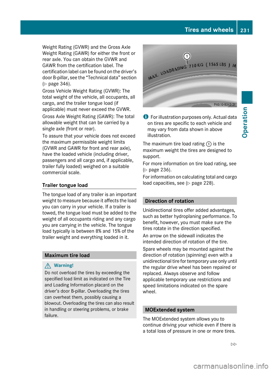
iFor illustration purposes only. Actual data
on tires are specific to each vehicle and
may vary from data shown in above
illustration.
The maximum tire load rating : is the
maximum weight the tires are designed to
support.
For more information on tire load rating, see
(Y page 236).
For information on calculating total and cargo
load capacities, see (Y page 228).
Direction of rotation
Unidirectional tires offer added advantages,
such as better hydroplaning performance. To
benefit, however, you must make sure the
tires rotate in the direction specified.
An arrow on the sidewall indicates the
intended direction of rotation of the tire.
Spare wheels may be mounted against the
direction of rotation (spinning) even with a
unidirectional tire for temporary use only until
the regular drive wheel has been repaired or
replaced. Always observe and follow
applicable temporary use restrictions and
speed limitations indicated on the spare
wheel.
MOExtended system
The MOExtended system allows you to
continue driving your vehicle even if there is
a total loss of pressure in one or more tires.
Tires and wheels231Operation164_AKB; 7; 31, en-USd2ureepe,Version: 2.11.8.12009-09-11T12:07:36+02:00 - Seite 231Z
Page 242 of 368

radio, and heater, to the extent that these
items are available as factory-installed
equipment (whether installed or not).
Air pressure
The amount of air inside the tire pressing
outward on each square inch of the tire. Air
pressure is expressed in pounds per square
inch (psi), kilopascal (kPa), or bar.
Aspect ratio
Dimensional relationship between tire
section height and section width expressed
in percentage.
Bar
Metric unit for air pressure. There are
14.5038 pounds per square inch (psi) to
1 bar; there are 100 kilopascals (kPa) to 1 bar.
Bead
The tire bead contains steel wires wrapped by
steel cords that hold the tire onto the rim.
Cold tire inflation pressure
Tire inflation pressure when your vehicle has
been sitting for at least 3 hours or driven no
more than 1 mile (1.6 km).
Curb weight
The weight of a motor vehicle with standard
equipment including the maximum capacity
of fuel, oil, and coolant, and, if so equipped,
air conditioning and additional optional
equipment, but without passengers and
cargo.
DOT (Department of Transportation)
A tire branding symbol which denotes the tire
meets requirements of the U.S. Department
of Transportation.
GAWR (Gross Axle Weight Rating)
The GAWR is the maximum permissible axle
weight. The gross vehicle weight on each axle
must never exceed the GAWR for the front
and rear axle indicated on the certification
label located on the driver’s door B-pillar.
GTW (Gross Trailer Weight)
The GTW is the weight of the trailer plus the
weight of all cargo, equipment, luggage etc.
loaded on the trailer.
GVW (Gross Vehicle Weight)
The GVW comprises the weight of the vehicle
including fuel, tools, spare wheel, installed
accessories, passengers and cargo and, if
applicable, trailer tongue load. The GVW must
never exceed the GVWR indicated on the
certification label located on the driver’s door
B-pillar.
GVWR (Gross Vehicle Weight Rating)
This is the maximum permissible vehicle
weight of the fully loaded vehicle (weight of
the vehicle including all options, passengers,
fuel, and cargo and, if applicable, trailer
tongue load). It is indicated on the
certification label located on the driver’s door
B-pillar.
Kilopascal (kPa)
Metric unit for air pressure. There are 6.9 kPa
to 1 psi; another metric unit for air pressure
is bar. There are 100 kilopascals (kPa) to
1 bar.
Load index
Numerical code associated with the
maximum load a tire can support.
Maximum load rating
The maximum load in kilograms and pounds
that can be carried by the tire.
240Tires and wheelsOperation
164_AKB; 7; 31, en-USd2ureepe,Version: 2.11.8.12009-09-11T12:07:36+02:00 - Seite 240
Page 257 of 368

The lowest value listed must be selected
when determining how the vehicle and
trailer are loaded.
R The tongue weight at the hitch ball must be
added to the rear axle weight to prevent
exceeding the rear Gross Axle Weight
Rating (GAWR). The GAWR is indicated on
the certification label located on the
driver’s door B-pillar ( Y page 227).
i Mercedes-Benz recommends loading the
trailer in such a manner that it has a tongue
weight between 8 % and 15 % of the GTW.
i The weight of other accessories,
passengers and cargo will reduce the
maximum trailer weight and tongue weight
your vehicle can tow.
Checking weights of vehicle and trailer
R To assure that the towing vehicle and trailer
are in compliance with the maximum
permissible weight limits, have the loaded
rig (towing vehicle including driver,
passengers and cargo, trailer fully loaded)
weighed on a commercial scale.
R Check the vehicle’s front and rear gross
axle weight, the Gross Trailer Weight (GTW)
and tongue weight.
The values as measured must not exceed
the weight limits listed under “Vehicle and
trailer weights and ratings” ( Y page 254).
Coupling a trailer GWarning!
Vehicles with air suspension program: While
you are coupling or decoupling a trailer, make
sure nobody locks or unlocks the vehicle and/
or opens or closes doors or the tailgate.
The vehicle’s level could change and you
could endanger yourself and/or others as a
result.
Make sure that you do not operate the ADS
switch or the vehicle level control system
when coupling/decoupling the trailer.
Observe maximum permitted trailer
dimensions (width and length).
Most states and all Canadian provinces
require
R safety chains between the towing vehicle
and the trailer
The chains should be criss-crossed under
the trailer tongue. They must be attached
to the hitch receiver, and not to the
vehicle’s bumper or axle.
Make sure to leave enough slack in the
chains to permit turning corners.
R a separate brake system at various trailer
weights
R a break-away switch on trailers with a
separate brake system.
Check with your local state laws for specific
requirements.
The switch activates the trailer brakes in
the possible event that the trailer might
separate from the tow vehicle.
! Do not connect a trailer brake system (if
trailer is so equipped) directly to the
vehicle’s hydraulic brake system, as your
vehicle is equipped with antilock brakes. If
you do, neither the vehicle’s brakes nor the
trailer’s brakes will function properly.
i The provided vehicle electrical wiring
harness for trailer towing has a brake signal
wire for hook-up to a brake controller.XMake sure the automatic transmission is in
park position P (Y page 110).XEngage the parking brake for the vehicle
( Y page 107).XStart the engine ( Y page 103).XVehicles with vehicle level control:
Select the highway level ( Y page 156).XVehicles with Adaptive Damping System
(ADS):
Set the ADS to AUTO or COMF
( Y page 156).XTurn off the engine ( Y page 108).Driving instructions255Operation164_AKB; 7; 31, en-USd2ureepe,Version: 2.11.8.12009-09-11T12:07:36+02:00 - Seite 255Z
Page 271 of 368

XRelease securing hook = (located below
the floor handle) from holder.
XEngage securing hook = on upper cargo
compartment lip ?.
! With the cargo compartment cover blind
installed behind the rear seats, disengage
cargo compartment cover blind and flip it
forward. Otherwise the strap of the
securing hook could damage the cargo
compartment cover blind.
! To prevent damage, always disengage the
securing hook from upper cargo
compartment lip and lower the cargo
compartment floor before closing the
tailgate.
Vehicles without spare wheel
iVehicles without spare wheel are not
factory-equipped with the tools required for
a wheel change such as a jack or a wheel
wrench. Some tools required for a wheel
change are specific to your vehicle.
Contact an authorized Mercedes-Benz
Center to obtain the tools approved for
your vehicle. The illustration shows the
vehicle retrofitted with the necessary tools
for a wheel change.
:Towing eye bolt;Alignment bolt=Jack?Fuse chartAElectric air pump27BTIREFIT kit27CWheel wrenchDCollapsible wheel chockEReversible ratchet for jack27ML 350 BlueTEC 4MATIC (Canada vehicles) factory equipped with 20" wheels only.Where will I find ...?269Practical hints164_AKB; 7; 31, en-USd2ureepe,Version: 2.11.8.12009-09-11T12:07:36+02:00 - Seite 269Z
Page 317 of 368

XTurn housing cover ; counterclockwise
and remove it.
XTurn bulb socket C with the bulb
counterclockwise and remove it.
XPull the bulb out of bulb socket C.XGently press the new bulb into bulb socket
C.
XPlace bulb socket C back into the housing
and turn it clockwise until it engages.
XAlign housing cover ; and turn it
clockwise until it engages.
Parking and standing lamp bulb,
front turn signal lamp bulb,
side marker lamp bulb
XTurn respective bulb socket =, ? or A
(Y page 314) with the bulb
counterclockwise and remove it.
XPull the bulb out of the bulb socket.XGently press the new bulb into the bulb
socket.
XPlace bulb socket =, ? or A back into
the housing and turn it clockwise until it
engages.
Replacing bulbs for rear lamps
Before you start to replace a bulb for a rear
lamp, do the following:
XSwitch off the ignition.XTurn the exterior lamp switch to position
$.
Tail lamp unit
To access the tail lamp units, you first have to
remove the cover in the corresponding side
trim panel of the cargo compartment.
XOpen the tailgate.Opening the driver’s side trim panelXTurn lock : counterclockwise by 90°.XRemove cover ;.
Removing storage compartment
Example illustration: Storage compartmentwithout sound system
XRemove everything from storage
compartment ;.
XInsert a suitable object such as a coin into
the slot of lock :.
XTurn lock : by 90° in direction of the
arrow.
XRemove storage compartment ;.Replacing bulbs315Practical hints164_AKB; 7; 31, en-USd2ureepe,Version: 2.11.8.12009-09-11T12:07:36+02:00 - Seite 315Z