2010 MERCEDES-BENZ ML350 Page 91
[x] Cancel search: Page 91Page 194 of 368

tie-down rings in the cargo compartment
(Y page 188).
XOpen the hook and loop fasteners on the
cargo net package.
XRoll out the cargo net.XUnfold the cargo net.XEngage the upper cargo net bar.
The cargo net bar must engage audibly.
Installing the cargo net
Cargo net installed behind the C-pillar
XHang cargo net bar ; on holder : as
indicated by the arrow.
XPush cargo net bar ; forward into
holder : in direction of arrow.
XEngage lower cargo net bar.
The cargo net bar must engage audibly.
Pulling the cargo net tight
Belt hook attached behind the rear seat backrests
XHook belt hook : into cargo tie-down
ring ; in direction of arrow.
XPull tightening belt = by the loose end in
direction of arrow until the cargo net is
pulled tight.
XAfter driving a short distance, make sure
the cargo net is still tight and, if necessary,
pull it tight again.
Loosening the cargo net
Belt hook attached behind the rear seat backrests
XLoosen the tightening belt by pulling
buckle : upward in direction of arrow.
XRemove belt hook ; from cargo tie-down
ring =.
Removing and storing the cargo net
XTake cargo net bar ; (Y page 192) out of
holder : (Y page 192).
XPress the red button on the upper and lower
cargo net bar.
XFold the cargo net.XRoll up the cargo net.XClose the hook and loop fasteners on the
cargo net package.
Front storage compartments
GWarning!
To help avoid personal injury during a collision
or sudden maneuver, exercise care when
192Loading and storingControls in detail
164_AKB; 7; 31, en-USd2ureepe,Version: 2.11.8.12009-09-11T12:07:36+02:00 - Seite 192
Page 195 of 368

storing objects in the vehicle. Put luggage or
cargo in the cargo compartment if possible.
Do not pile luggage or cargo higher than the
seat backrests.
If so equipped, always use the cargo net when
transporting cargo. The cargo net cannot
secure hard or heavy objects.
Parcel nets cannot secure hard or heavy
objects.
Keep compartment lids closed. This will help
to prevent stored objects from being thrown
about and injuring vehicle occupants during
Rbraking
Rvehicle maneuvers
Ran accident
Glove box
Depending on vehicle equipment, an AUX
socket or a media interface is located in the
glove box. For information on Audio AUX
mode or on media interface, see separate
COMAND system operating instructions.
XOpening: Pull glove box lid release :.XClosing: Push glove box lid ; upwards
until it engages.
You can lock the glove box, e.g. when the
vehicle is in the shop for service.
The glove box can only be locked or unlocked
with the mechanical key.
1Glove box unlocked2Glove box locked
Storage compartment in front center
console
XPress the front of the cover briefly.
The cover opens automatically.
Front armrest storage compartment
iThe Roadside Assistance button º
(Y page 201) and the Information button
Loading and storing193Controls in detail164_AKB; 7; 31, en-USd2ureepe,Version: 2.11.8.12009-09-11T12:07:36+02:00 - Seite 193Z
Page 196 of 368

E (Y page 202) are located in the
storage compartment.
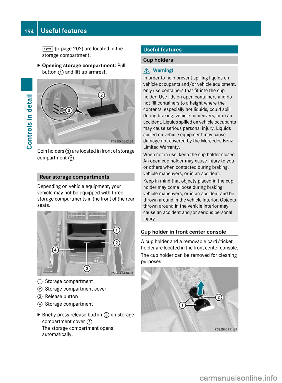
XOpening storage compartment: Pull
button : and lift up armrest.
Coin holders = are located in front of storage
compartment ;.
Rear storage compartments
Depending on vehicle equipment, your
vehicle may not be equipped with three
storage compartments in the front of the rear
seats.
:Storage compartment;Storage compartment cover=Release button?Storage compartmentXBriefly press release button = on storage
compartment cover ;.
The storage compartment opens
automatically.
Useful features
Cup holders
GWarning!
In order to help prevent spilling liquids on
vehicle occupants and/or vehicle equipment,
only use containers that fit into the cup
holder. Use lids on open containers and do
not fill containers to a height where the
contents, especially hot liquids, could spill
during braking, vehicle maneuvers, or in an
accident. Liquids spilled on vehicle occupants
may cause serious personal injury. Liquids
spilled on vehicle equipment may cause
damage not covered by the Mercedes-Benz
Limited Warranty.
When not in use, keep the cup holder closed.
An open cup holder may cause injury to you
or others when contacted during braking,
vehicle maneuvers, or in an accident.
Keep in mind that objects placed in the cup
holder may come loose during braking,
vehicle maneuvers, or in an accident and be
thrown around in the vehicle interior. Objects
thrown around in the vehicle interior may
cause an accident and/or serious personal
injury.
Cup holder in front center console
A cup holder and a removable card/ticket
holder are located in the front center console.
The cup holder can be removed for cleaning
purposes.
194Useful featuresControls in detail
164_AKB; 7; 31, en-USd2ureepe,Version: 2.11.8.12009-09-11T12:07:36+02:00 - Seite 194
Page 198 of 368

Vanity mirror
Vanity mirror lamp = only functions when
sun visor : is engaged in mounting C.
XFlip sun visor down.XLift up vanity mirror cover ?.
Vanity mirror lamp = comes on.
Ashtrays
Center console ashtray
iA storage compartment is located under
the ashtray insert.
! The storage compartment is not heat-
proof. Therefore, do not stub cigarettes in
the storage compartment.
XOpening: Press cover ; briefly.XRemoving ashtray insert: Grab ashtray
insert : on the sides and pull it out
upwards.
XReinstalling ashtray insert: Install
ashtray insert :.
XClosing: Push cover ;.
Rear center console ashtray
! Close the ashtray when not in use and
before folding the rear seats. Otherwise
you could damage the ashtray.
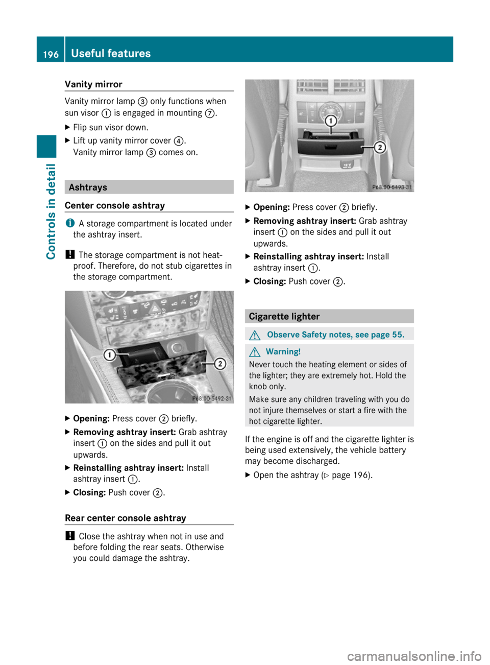
XOpening: Press cover ; briefly.XRemoving ashtray insert: Grab ashtray
insert : on the sides and pull it out
upwards.
XReinstalling ashtray insert: Install
ashtray insert :.
XClosing: Push cover ;.
Cigarette lighter
GObserve Safety notes, see page 55.GWarning!
Never touch the heating element or sides of
the lighter; they are extremely hot. Hold the
knob only.
Make sure any children traveling with you do
not injure themselves or start a fire with the
hot cigarette lighter.
If the engine is off and the cigarette lighter is
being used extensively, the vehicle battery
may become discharged.
XOpen the ashtray (Y page 196).196Useful featuresControls in detail
164_AKB; 7; 31, en-USd2ureepe,Version: 2.11.8.12009-09-11T12:07:36+02:00 - Seite 196
Page 200 of 368

Cargo compartment
115V AC Socket
GWarning!
The 115V AC socket operates at high voltage.
Use the 115V AC socket in the vehicle with
the same caution and prudence that you
exercise when using power outlets at home.
Keep any fluids away from the 115V AC
socket. Do not clean the socket with fluids or
tapered objects. Keep the 115V AC socket
cover in the closed position, when not in use.
Otherwise, you could suffer an electric shock
and be seriously or even fatally injured.
GWarning!
A device that you connect must have a
suitable plug that complies with U.S.
standards. Never pull on the cable to unplug
a plug from the 115V AC socket. Do not use
a damaged connection cable. The 115V AC
socket may not be connected to another
115V AC power source. Do not use converters
to a grounding plug with the 115V AC socket.
This could cause serious personal injury to
you and/or others.
GWarning!
If the 115V AC socket is damaged or torn out
of the trim, do not use or touch the 115V AC
socket. Using a 115V AC socket that is
damaged or torn out of the trim could cause
serious personal injury to you and/or others.
The 115V AC socket : provides an
alternating current of 115 volts, which
enables you to connect small electrical
devices with a combined received power of
150 W at most. You can connect small
devices such as game consoles, mobile
phone chargers, laptops, etc.
Prerequisites for operation:
RThe 12V power outlets in the second-row
footwell and cargo compartment
(Y page 197) are operational.
RThe plug of the small device must be
inserted fully into 115V AC socket :.
RThe on-board voltage of the vehicle is within
the permissible voltage range.
RThe specified wattage of the small device
is identical or lower than the maximum
permissible wattage (150 W) of the 115V
AC socket :.
XOperation: Open cover =.XInsert the plug of the small device into
115V AC socket :.
LED ; comes on.
If LED ; does not come on, refer to the
section on possible nonoperation causes.
XSwitching off: Pull the plug out of 115V AC
socket :.
Do not pull on the cable.
XClose cover =.
Possible nonoperation causes:
RThe on-board voltage of the vehicle is not
within the permissible voltage range.
198Useful featuresControls in detail
164_AKB; 7; 31, en-USd2ureepe,Version: 2.11.8.12009-09-11T12:07:36+02:00 - Seite 198
Page 202 of 368

RThe indicator lamp in the SOS button does
not come on during the system self-test.
R The indicator lamp in Roadside Assistance
button º does not come on during the
system self-test.
R The indicator lamp in Information button
E does not come on during the system
self-test.
R The indicator lamp in the SOS button,
Roadside Assistance button º, or
Information button E remains
illuminated constantly in red after the
system self-test.
R The message Tele Aid Inoperative or
Tele Aid Not Activated appears in the
multifunction display after the system self-
test
If a malfunction is indicated as outlined above,
the system may not operate as expected. In
case of an emergency, help will have to be
summoned by other means.
Have the system checked at the nearest
Mercedes-Benz Center or contact the
Customer Assistance Center at
1-800-FOR-MERCedes (1-800-367-6372)
(USA only) or 1-888-923-8367 (Canada only)
as soon as possible.
Emergency calls
! In order to activate the Tele Aid system, a
subscriber agreement must be completed.
To ensure your system is activated and
operational, please press Information
button E to perform the acquaintance
call. Failure to complete either of these
steps may result in a system that is not
activated.
If you have any questions regarding
activation, please call the Customer
Assistance Center at
1-800-FOR-MERCedes (1-800-367-6372)
(USA only) or 1-888-923-8367 (Canada
only).
An emergency call is initiated automatically
following an accident in which the Emergency
Tensioning Devices (ETDs) or air bags have
deployed.
i An automatically initiated Tele Aid
emergency call cannot be canceled.
An emergency call can also be initiated
manually ( Y page 201).
Once the emergency call is in progress, the
indicator lamp in the SOS button will begin to
flash. The message Connecting Call
appears in the multifunction display and the
COMAND system is muted. When the
connection is established, the message
Call Connected appears in the
multifunction display.
All information relevant to the emergency,
such as the location of the vehicle
(determined by the GPS satellite location
system), vehicle model, identification number
and color are generated.
A voice connection between the Customer
Assistance Center and the occupants of the
vehicle will be established automatically soon
after the emergency call has been initiated.
The Customer Assistance Center will attempt
to determine the nature of the emergency
more precisely, provided they can speak to
an occupant of the vehicle.
i If no vehicle occupant responds, an
ambulance will be sent to the vehicle
immediately.GWarning!
If the indicator lamp in the SOS button is
flashing continuously and there was no voice
connection to the Customer Assistance
Center established, then the Tele Aid system
could not initiate an emergency call (e.g. the
relevant cellular phone network is not
available).
The message Call Failed appears in the
multifunction display for approximately
10 seconds.
200Useful featuresControls in detail
164_AKB; 7; 31, en-USd2ureepe,Version: 2.11.8.12009-09-11T12:07:36+02:00 - Seite 200
Page 203 of 368

Should this occur, assistance must be
summoned by other means.
iThe “911” emergency call system is a
public service. Using it without due cause
is a criminal offense.
Initiating an emergency call manually
XBriefly press on cover : to open.XPress SOS button ; briefly.
The indicator lamp in SOS button ; will
flash until the emergency call is concluded.
XWait for a voice connection to the
Customer Assistance Center.
XClose cover : after the emergency call is
concluded.
GWarning!
If you feel at any way in jeopardy when in the
vehicle (e.g. smoke or fire in the vehicle,
vehicle in a dangerous road location), please
do not wait for voice contact after you have
pressed the emergency button. Carefully
leave the vehicle and move to a safe location.
The Customer Assistance Center will
automatically contact local emergency
officials with the vehicle’s approximate
location if they receive an automatic SOS
signal and cannot make voice contact with the
vehicle occupants.
XTerminating calls: Press button ~ on
the multifunction steering wheel.
or
XPress the respective button for ending a
telephone call on the COMAND system.
Roadside Assistance button
XOpen the front armrest storage
compartment (Y page 193).
XPress and hold Roadside Assistance
button : for longer than 2 seconds.
A call to a Mercedes-Benz Roadside
Assistance dispatcher will be initiated. The
indicator lamp in Roadside Assistance
button : will flash while the call is in
progress. The message Connecting
Call will appear in the multifunction
display and the COMAND system is muted.
When the connection is established, the
message Call Connected appears in the
multifunction display. The Tele Aid system will
transmit data generating the vehicle
identification number, model, color and
location (subject to availability of cellular and
GPS signals).
i The COMAND system display indicates
that a Tele Aid call is in progress. While the
call is connected you can change to the
navigation menu by pressing the NAVI
button on the COMAND system. Spoken
commands are not available.
Useful features201Controls in detail164_AKB; 7; 31, en-USd2ureepe,Version: 2.11.8.12009-09-11T12:07:36+02:00 - Seite 201Z
Page 204 of 368

A voice connection between the Roadside
Assistance dispatcher and the occupants of
the vehicle will be established.
XDescribe the nature of the need for
assistance.
The Mercedes-Benz Roadside Assistance
dispatcher will either dispatch a qualified
Mercedes-Benz technician or arrange to tow
your vehicle to the nearest authorized
Mercedes-Benz Center. For services such as
labor and/or towing, charges may apply.
Refer to the Roadside Assistance manual for
more information.
Sign and Drive services (USA only):
Services such as a jump start, a few gallons
of fuel or the replacement of a flat tire with
the vehicle spare wheel are obtainable at no
charge.
iIf the indicator lamp in Roadside
Assistance button : is flashing
continuously and there was no voice
connection to the Customer Assistance
Center established, then the Tele Aid
system could not initiate a Roadside
Assistance call (e.g. the relevant cellular
phone network is not available). The
message Call Failed appears in the
multifunction display.
XTerminating calls: Press button ~ on
the multifunction steering wheel.
or
XPress the respective button for ending a
telephone call on the COMAND system.
Information button
XOpen the front armrest storage
compartment (Y page 193).
XPress and hold Information button : for
longer than 2 seconds.
A call to the Customer Assistance Center
will be initiated. The indicator lamp in
Information button : will flash while the
call is in progress. The message
Connecting Call will appear in the
multifunction display and the COMAND
system is muted.
When the connection is established, the
message Call Connected appears in the
multifunction display. The Tele Aid system will
transmit data generating the vehicle
identification number, model, color and
location (subject to availability of cellular and
GPS signals).
i The COMAND system display indicates
that a Tele Aid call is in progress. While the
call is connected you can change to the
navigation menu by pressing the NAVI
button on the COMAND system. Spoken
commands are not available.
A voice connection between the Customer
Assistance Center representative and the
occupants of the vehicle will be established.
Information regarding the operation of your
vehicle, the nearest authorized Mercedes-
Benz Center or Mercedes-Benz USA products
and services is available to you.
For more details concerning the Tele Aid
system, please visit www.mbusa.com (USA
only), log in to “Owner’s Online” and visit the
“My Tele Aid” section to learn more.
202Useful featuresControls in detail
164_AKB; 7; 31, en-USd2ureepe,Version: 2.11.8.12009-09-11T12:07:36+02:00 - Seite 202